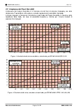
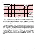
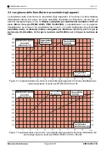
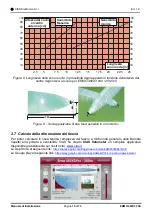
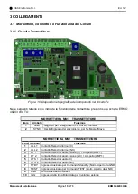
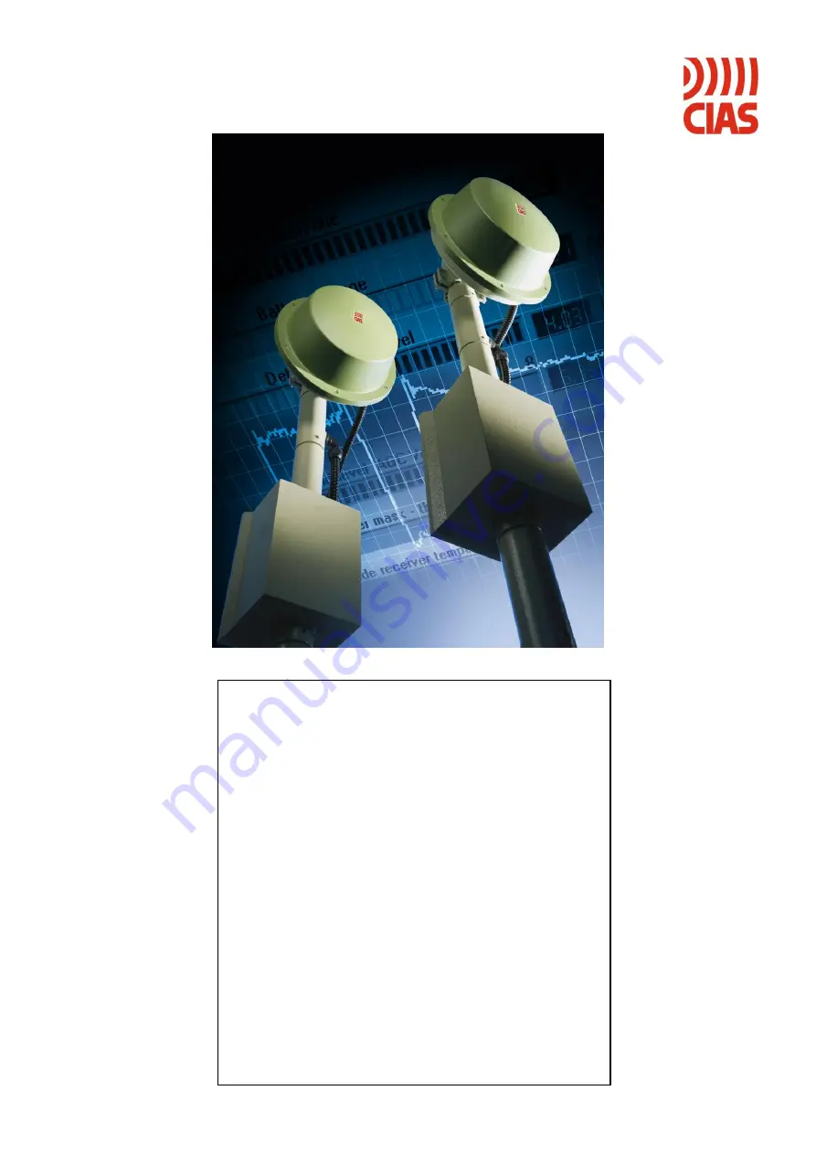
background image

20MACIE0343 


ERMO 482X3


PRO


Barriera a Microonde 

per protezioni esterne 

Manuale di Installazione 


External Microwave Protection 

Barrier  

Installation Handbook 


Edizione / Edition 1.2 


Summary of Contents for ERMO 482X3 PRO

Page 1: ...20MACIE0343 ERMO 482X3 PRO Barriera a Microonde per protezioni esterne Manuale di Installazione External Microwave Protection Barrier Installation Handbook Edizione Edition 1 2 ...

Page 2: ...ONE PRINCIPALE 21 3 2 1 Collegamento all Alimentazione 21 3 2 2 Collegamento all Alimentazione di Riserva 21 3 3 COLLEGAMENTO ALLA CENTRALE 22 3 3 1 Contatti di allarme Allarme Guasto Manomissione 22 3 3 2 Connessioni per Sincronismo 23 3 3 3 Connessioni per Stand by 23 3 3 4 Connessioni per Test 23 3 3 5 Connessioni per Linea Bilanciata 23 LINEA SERIALE RS 485 25 3 3 6 Interfaccia Linea Seriale R...

Page 3: ...PMENT CONNECTION TO THE POWER SUPPLY 57 3 2 1 Connection to the Power Supply 57 3 2 2 Connection of stand by Battery 57 3 3 CONNECTION TO THE CONTROL PANEL 58 3 3 1 Alarm contacts Alarm Tamper Fault 58 3 3 2 Synchronism connection 59 3 3 3 Stand by connection 59 3 3 4 Test connection 59 3 3 5 Balanced Line connection 59 3 4 SERIAL LINE RS 485 61 3 4 1 RS 485 232 USB Network Connection Interface 61...

Page 4: ...nsibile instauratosi tra il Trasmettitore TX e il Ricevitore RX Il segnale ricevuto viene analizzato digitalmente attraverso i metodi della logica Fuzzy permettendo di raggiungere eccellenti prestazioni nella rilevazione e la diminuzione dei Falsi Allarmi ERMO 482X3 PRO è disponibile con le seguenti portate ERMO 482X3 PRO 050 Portata 50 metri ERMO 482X3 PRO 080 Portata 80 metri ERMO 482X3 PRO 120 ...

Page 5: ... 73 ERMO 482X3 PRO 1 2 Schema a blocchi Negli schemi a blocchi che seguono sono rappresentati i gruppi funzionali della testa Trasmittente e Ricevente della barriera ERMO 482X3 PRO Schema a blocchi ERMO 482X3 PRO Trasmettitore Schema a blocchi ERMO 482X3 PRO Ricevitore ...

Page 6: ...bile installare un numero di tratte pari Questa considerazione è legata al fatto che le possibili interferenze reciproche tra tratte contigue vengono annullate nel caso in cui ai vertici Incroci del poligono risultante dall installazione stessa vengano installati due rivelatori aventi lo stesso nome cioè due trasmettitori o due ricevitori E evidente che ciò può avvenire solo nel caso che il numero...

Page 7: ... il loro movimento potrebbe creare dei disturbi in caso contrario contattare l assistenza tecnica CIAS recinzioni metalliche poste dietro gli apparati possono provocare talvolta distorsioni del fascio sensibile e quindi dare luogo a falsi allarmi Gli alberi le siepi i cespugli la vegetazione in genere richiede una grand attenzione qualora ve ne sia in prossimità o entro i fasci di protezione Quest...

Page 8: ...la lunghezza della tratta nel caso di sensibilità massima e minima per i diversi modelli di apparecchio impiegati 1 2 3 4 5 6 7 8 9 10 5 10 15 20 25 30 35 40 45 50 Diametro zona sensibile a metà tratta m Sensibilità Massima Lunghezza della tratta m Sensibilità minima Figura 3 Diametro della zona sensibile a metà tratta per ERMO 482X3 PRO 50 20 40 60 80 100 120 140 160 180 200 Diametro zona sensibi...

Page 9: ...È inoltre importante ricordare che la soglia di preallarme determina il livello di inizio elaborazione cioè tutti i segnali che stanno al di sotto di tale soglia sono considerati disturbo o rumore Tutti i segnali che superano questa soglia danno luogo alla elaborazione del segnale secondo le regole Fuzzy previste Se dopo aver superato la soglia di preallarme il segnale di intrusione resta per circ...

Page 10: ...anza minima consigliata per effettuare l Incrocio è di 5 m per le barriere da 80 120 200m 12 5m per le barriere da 250 500m e di 3 5m per le barriere da 50m 20 30 10 40 50 60 70 80 90 100 20 30 10 40 50 60 70 80 90 100 1 2 3 4 5 6 7 8 9 10 Altezza dal suolo al centro antenna cm Sensibilità Massima Lunghezza zona morta m Sensibilità minima Figura 6 Lunghezza della zona morta in prossimità degli app...

Page 11: ...i stessi al suolo per ERMO 482X3 PRO 250 500 5 M 80 85 cm Figura 9 Sovrapposizione di due fasci sensibili in un incrocio 2 7 Calcolo della dimensione del fascio Per poter calcolare in linea teorica l ampiezza del fascio a microonda generato dalle Barriere rispetto alla portata e sensibilità CIAS ha creato CIAS Volumeter un semplice applicativo disponibile gratuitamente sul nostro sito www cias it ...

Page 12: ... o rete metallica potrebbe accadere che la microonda veda 2 piani il muro rete e il terreno L altezza installativa idonea si ricava tramite lo strumento di allineamento incorporato E necessario che il campo microonda sia stabile Qui di seguito verranno riportati alcuni esempi installativi 1 Esempio Palo sullo stesso piano di lavoro della microonda Questa soluzione installativa è la più semplice po...

Page 13: ...iano di lavoro della microonda La testa Tx1 si trova su un piano differente dall Rx1 posizionato invece sul piano di lavoro della barriera 2 5 Esempio cambio pendenza installazione consigliata Palo a un livello differente rispetto al piano di lavoro della microonda La testa Tx1 si trova su un piano differente dall Rx1 posizionato invece sul piano di lavoro della barriera 2 6 Esempio cambio pendenz...

Page 14: ... un piano differente rispetto alla barriera 2 E necessario installare due distinte barriere considerando due differenti piani di lavoro e proteggere le zone d ombra di Rx1 e Rx2 con due sensori supplementari 8 Esempio forte avvallamento del terreno II forte avvallamento del terreno crea una considerevole zona d ombra che deve essere protetta con un sensore supplementare ...

Page 15: ... il piano di lavoro sia uno solo Considerazioni da effettuare prima dell installazione Utilizzare la staffa corretta in relazione alla distanza Scegliere l altezza adatta al tipo di applicazione protezione muro o finestre Posizionare la barriera considerando la sua zona d ombra e il suo lobo di protezione Verificare se la parete è piana o presenta sporgenze colonne tubi di scarico gronde davanzali...

Page 16: ...tivo per collegamento cavo di sincronismo 2 SYNC Uscita Ingresso del sincronismo per Tx Master Slave MORSETTIERA MS2 TRASMETTITORE Mors Simbolo Funzione 1 ALL 1 Contatto Relè di Allarme C 2 ALL 2 Contatto Relè di Allarme NC 3 PT 1 Contatto Relè di Manomissione C Ampolla AMP1 4 PT 2 Contatto Relè di Manomissione NC Ampolla AMP1 5 GTS 1 Contatto Relè di Guasto C 6 GTS 2 Contatto Relè di Guasto NC 7 ...

Page 17: ... d Alimentazione 19 V o 24V CONNETTORE J2 TRASMETTITORE Connettore 10 pin Linea Seriale per Software di gestione Mors Simbolo Funzione 1 2 N C Non Connesso 3 13 8 Alimentazione 13 8 V convertitore interfaccia RS 485 232 4 N C Non Connesso 5 LO Linea Bassa per RS 485 6 N C Non Connesso 7 LH Linea Alta per RS 485 8 N C Non Connesso 9 GND Massa 10 N C Non Connesso CONNETTORE J3 TRASMETTITORE Connetto...

Page 18: ...METTITORE Simbolo Funzione Default D8 Indicazione Guasto ON D9 Indicazione Manomissione ON D10 Indicazione Allarme ON D31 Indicazione Presenza Rete ON JUMPERS DEL TRASMETTITORE Simbolo Funzione Default Jp1 Modulazione Interna Jp1 posizione 2 3 Tx Master Sync Out o Esterna Jp1 posizione 1 2 Tx Slave Sync In OUT Jp2 Esclusione led di indicazione guasto allarme e manomissione Jp2 posizione 2 3 led es...

Page 19: ...RSETTIERA MS1 RICEVITORE Mors Simbolo Funzione 1 ALL 1 Contatto Relè di Allarme C 2 ALL 2 Contatto Relè di Allarme NC 3 PT 1 Contatto Relè di Manomissione C Ampolla AMP1 4 PT 2 Contatto Relè di Manomissione NC Ampolla AMP1 5 GTS 1 Contatto Relè di Guasto C 6 GTS 2 Contatto Relè di Guasto NC 7 ST BY Ingresso Ausiliario Comando Stand By Norm Aperto da GND 8 TEST Ingresso Ausiliario Comando TEST Norm...

Page 20: ...e CONNETTORE J3 RICEVITORE Mors Simbolo Funzione 1 2 3 5 7 8 10 11 12 13 15 16 N C Non Connesso 4 GND 6 Tensione di Alimentazione 13 8 V 9 0 2V Onda Quadra 200 mVpp 14 VRAG Tensione del Regolatore Automatico di Guadagno CONNETTORE J6 RICEVITORE Connettore per microinterruttore apertura Radome Tamper Mors Simbolo Funzione 1 GND Collegamento di Massa per Tamper 2 ING Ingresso Tamper 3 GND Collegamen...

Page 21: ...1 Posizione 1 Allineamento Barriera Posizione 2 Acquisizione Canale e valore di campo Posizione 3 Lettura Scrittura Soglia di preallarme Posizione 4 Lettura Scrittura Soglia di allarme Walk Test Posizione 5 Lettura Scrittura Soglia di Mascheramento Posizione 6 Lettura Scrittura Soglia di Preallarme Superiore FSTD Posizione 7 Lettura Scrittura Soglia Allarme Superiore FSTD Posizione 8 Lettura Scrit...

Page 22: ...e In ogni caso occorre attenersi scrupolosamente alle prescrizioni contenute nelle leggi e normative vigenti in materia di installazioni fisse di apparati collegati permanentemente alla rete di alimentazione come la Legge 46 90 e la Normativa CEI 64 8 3 2 2 Collegamento all Alimentazione di Riserva All interno di ciascuna testa è previsto lo spazio per alloggiare una Batteria ricaricabile al piomb...

Page 23: ... su Ricevitore 4 Allarme del rivelatore connesso sulla Linea Bilanciata Ausiliaria TX e RX 5 Risultato Positivo dell esecuzione di una procedura di Test su Ricevitore 6 Segnale ricevuto insufficiente V RAG 5 5V 7 Allarme canale Nota 2 RELE di MANOMISSIONE 1 Rimozione del coperchio Radome 2 Sposizionamento Ampolla 3 Manomissione del rivelatore connesso sulla Linea Bilanciata Ausiliaria 4 Taglio del...

Page 24: ...to 7 STBY di MS1 sul Ricevitore o il morsetto 7 STBY di MS2 sul Trasmettitore N B lo Stand by non inibisce la funzionalità della barriera ma disattiva la registrazione degli eventi nel file storico TX e RX e nel file di monitor del ricevitore 3 3 4 Connessioni per Test La funzione di test viene attivata connettendo il morsetto 8 TEST della morsettiera MS2 del circuito Trasmettitore a GND Se la pro...

Page 25: ...re una pesatura mediante resistori collegati come nella seguente figura Nella tabella riportata sono indicati i valori di tensione che si localizzano sui morsetti di ingresso della linea bilanciata per i vari stati del rivelatore esterno e della linea che lo collega alla testa TX o RX Questi valori possono essere letti anche mediante il SW WAVE TEST2 nella schermata Valori Analogici sia con un PC ...

Page 26: ...tore 25 pin D Type del convertitore Morsettiera convertitore USB RS485 N N N Simbolo Funzione 1 12 13 8 Alimentazione 13 8 V per convertitore 485 232 2 9 1 GND Massa dati e alim per convertitore 485 232 3 10 2 LH 485 Linea dati Alta per RS 485 4 11 3 LO 485 Linea dati Bassa per RS 485 3 3 8 Configurazione Rete e Rigeneratori di segnale La connessione seriale tra le varie teste di tutte le barriere...

Page 27: ...ari a 32 compreso il BUSREP e nella prima tratta compreso il convertitore di linea seriale 1 13 8 Vcc 0 Vcc ALIMENTATORE LOCALE CONVERTITORE DI LINEA SERIALE RS 485 RS 232 RS 485 RS232 13 1 1 1 ESTENSIONE DELLA DISTANZA IMPIEGANDO BUSREP COME RIGENERATORE Nella figura è rappresentato un impianto che richiede una linea seriale RS 485 di lunghezza superiore a 1200 mt Essa è stata spezzata utilizzand...

Page 28: ...osizionando correttamente i faston l apparecchiatura riprenderà a funzionare regolarmente 4 Per ogni testa TX sono disponibili due modalità di impostazione del numero di tratta 1 Assegnazione locale non modificabile da remoto Assegnazione scrittura del numero di tratta Selezionare un numero da 1 a 99 sugli appositi commutatori SW2 unità e SW3 decine L impostazione 00 corrisponde alla tratta 100 Se...

Page 29: ...rriera è però buona norma predisporre canali differenti per le differenti barriere di un impianto in modo da accrescerne le doti di insabotabilità Impostando il commutatore sul canale F qualora si avessero le condizioni di allarme canale questo non genererebbe l evento d allarme N B qualora vi fosse la probabilità che due barriere si interferiscano reciprocamente perché i segnali a MW dell una pos...

Page 30: ...uesta operazione attiva la fase di installazione della barriera c Premere il pulsante S2 Tale operazione attiverà il sistema di regolazione rapida del segnale ricevuto Dopo qualche secondo il sistema di regolazione rapida del segnale si arresta ed i leds rossi D13 e D12 saranno accesi mentre i leds verdi D11 D10 e D8 risulteranno spenti ed il Buzzer BZ1 emetterà un suono intermittente ad indicare ...

Page 31: ...ente il pulsante S2 dopo essersi assicurati che non vi siano disturbi nel campo di protezione Qualora si accendessero solo i 2 leds rossi significa che la procedura non è andata a buon fine ripetere tutta la procedura di allineamento accertandosi che non vi siano ostacoli o disturbi nel campo di protezione ritornare quindi in questa fase e premere nuovamente il pulsante S2 k Portando il commutator...

Page 32: ...se la frequenza cresce significa che il segnale perturbante è cresciuto quindi indica una maggiore penetrazione dell intruso nel campo di protezione se il segnale perturbante raggiunge le condizioni per determinare un evento di allarme il buzzer verrà attivato con un suono continuo In questo modo è possibile valutare la reale consistenza del fascio sensibile ed anche verificare se presunte fonti d...

Page 33: ...gere e o cambiare il valore della soglia di allarme superiore Come già visto al punto precedente per la soglia di preallarme superiore per attivare il sistema FSTD anche la soglia di allarme superiore deve essere impostata ad un valore più alto rispetto a quello settato nella fase l Lettura del valore attuale della soglia di allarme superiore Ruotare il commutatore SW3 decine fino a che il primo l...

Page 34: ...ttuale della soglia di monitor superiore Ruotare il commutatore SW3 decine fino a che il primo led rosso D13 sia acceso Ruotare il commutatore SW2 unità fino a che il secondo led rosso D12 sia acceso Il valore letto su questi due commutatori varia da 05 a 80 Valore di default 15 Modifica del valore attuale della soglia di monitor superiore Ruotare i commutatori SW2 unità e SW3 decine sul valore de...

Page 35: ...è possibile attivare o disattivare la linea bilanciata paragrafo 3 3 5 Lettura dello stato attuale della linea bilanciata linea bilanciata attiva o disattiva Ruotare il commutatore SW3 decine sulla posizione 0 accensione primo led rosso D13 Ruotare il commutatore SW2 unità sulla posizione 0 o 1 se il secondo led rosso D12 si accende sullo 0 allora la linea bilanciata è disattiva altrimenti se si a...

Page 36: ...izzare e gestire con estrema precisione tutti i parametri software della barriera compresi i livelli analogici delle soglie e del segnale ricevuto è possibile utilizzare un PC con il programma WAVE TEST2 CIAS riferirsi alla documentazione tecnica di questo programma per le procedure di collegamento e o gestione delle funzionalità software ...

Page 37: ...non vi è sensore disattivarla TX chiudere il ponticello JP4 RX seguire le indicazioni nel Capitolo 4 1 2 punto u VRag elevato Teste disallineate Eseguire il puntamento come descritto nel capitolo 4 1 2 punti a b c d e f g h i Ostacoli nel campo protetto Rimuovere gli ostacoli Segnale trasmesso insufficiente Controllare il Trasmettitore Circuito guasto Sostituire il Ricevitore Ricevitore a microond...

Page 38: ...anza mA 175 183 190 Corrente d alimentazione TX in allarme mA 130 139 145 Corrente d alimentazione RX in vigilanza mA 145 137 145 Corrente d alimentazione RX in allarme mA 120 125 130 Corrente d alimentazione TX in vigilanza mA 80 84 90 Corrente d alimentazione TX in allarme mA 60 61 65 Corrente d alimentazione RX in vigilanza mA 60 63 65 Corrente d alimentazione RX in allarme mA 50 56 60 Alloggia...

Page 39: ... Disponibilità Sul trasmettitore di un ingresso di sincronismo proveniente da un altro trasmettitore che possa interferire 17 Disponibilità In morsettiera di un uscita per collegare una batteria 12V 2 Ah per l alimentazione in assenza di rete 18 Disponibilità Sul trasmettitore di un commutatore a 16 posizioni che consente di stabilire quale canale di modulazione utilizzare Il ricevitore durante la...

Page 40: ...he sensitive field present between a transmitter Tx and a receiver Rx The received signal is processed in digital way and analysed with Fuzzy logic in order to obtain maximum performances and a minimum of false alarm rate The ERMO 482X3 PRO equipment is available with the following field range ERMO 482X3 PRO 050 Range 50 meters ERMO 482X3 PRO 080 Range 80 meters ERMO 482X3 PRO 120 Range 120 meters...

Page 41: ...andbook Page 40 of 73 ERMO 482X3 PRO 1 2 Block Diagram In the following diagrams are showed the functional block of the complete ERMO 482X3 Pro Transmitter and Receiver ERMO 482X3 PRO Transmitter Block Diagram ERMO 482X3 PRO Receiver Block Diagram ...

Page 42: ...f sections This consideration is bound to the fact that the likely reciprocal interferences between adjacent sections are annulled should at the vertices cross of the polygon resulting from the installation of the various sections be installed two equipment with the same name two transmitters or two receivers It is evident that this might occur only if the number of sections is even Should it not ...

Page 43: ... corridor between two metallic fences the width of the corridor should be not less to 5 m if less contact CIAS technical assistance Along the section within the area of the protection field are allowed pipes poles or similar e g lamp posts as long as their dimensions with respect to the protection beam are not too excessive The trees hedges bushes in general need very great attention if near or wi...

Page 44: ...ion based on the length of the section in case of maximum and minimum sensitivity see next figures 1 2 3 4 5 6 7 8 9 10 5 10 15 20 25 30 35 40 45 50 Half range sensitive zone diameter m Range m Maximum sensitivity Minimum sensitivity Figure 3 Diameter of sensitive beam at the half section length ERMO 482X3 PRO 50 20 40 60 80 100 120 140 160 180 200 2 4 6 8 10 12 14 16 18 20 Half range sensitive zo...

Page 45: ...sensitivity beam at half section length is that of the pre alarm threshold The higher the pre alarm threshold the lower the sensitivity and vice versa It s important to keep in mind that the pre alarm threshold determines the beginning of the intelligent analysis all signals below this threshold are considered noise and anyway of low importance All the signals higher this threshold are analyzed fo...

Page 46: ...t 90cm for 50 250 500m barriers With medium sensitivity setting the suggested crossing overlap is 5m for the 80 120 200m 12 5m for 250 500m barriers versions and 3 5m for the 50m version 20 30 10 40 50 60 70 80 90 100 20 30 10 40 50 60 70 80 90 100 1 2 3 4 5 6 7 8 9 10 Antenna centre height from ground cm Dead Zone lenght m Maximum sensitivity Minimum sensitivity Figure 6 ERMO 482X3 PRO 50 Dead zo...

Page 47: ...ight 5 M 80 85 cm Dead Zone Dead Zone 2 7 How to calculate the size of the beam and dead zones In order to calculate theoretically the dimension of the microwave beam and the dead zones generated with respect to the variable distance between TX and RX CIAS has created a simple application called CIAS Volumeter available for free on our website www cias it or on App Store to the following link http...

Page 48: ... wall or metallic fence it could happen that the microwave consider two planes i e the wall fence and the ground The correct height is obtained through the incorporated alignment tools Microwave field stability is required 1 Example Pole on the same level of microwave working plane This is the simplest solution for installation because the working plane is flat and the poles are at the same height...

Page 49: ...n on not aligned working planes Tx1 is on a different working plane from Rx1 placed instead on the working plane of barrier 2 5 Example changing slope suggested installation Pole on a different level from the working plane for installation on not aligned working planes Tx1 is on a different working plane from Rx1 placed instead on the working plane of barrier 2 6 Example changing slope installatio...

Page 50: ...ing plane than barrier 2 In this case since the change of slope is a step you must install two separate barriers and consider two different working planes always protecting dead zones resulting between Rx1 and Rx2 with two additional sensors 8 Example Strong dip in the ground The strong dip in the ground creates a considerable dead zone that has be protected with an additional sensor ...

Page 51: ...ne for the barrier take care to have just one working plane Take care of the following before installation Use the right bracket according to distance Choose the right height according to kind of application protection of windows or walls Place the barrier taking into consideration the volume of its beam and relevant dead zone Check if the surface of the wall is free or with any obstacles columns ...

Page 52: ...2 SYNC Sync In Out connection to perform Slave Master operation setting JP1 TRANSMITTER TERMINAL BLOCK MS2 Term Symbol Function 1 ALL 1 Alarm relay contact Normally Closed 2 ALL 2 Alarm relay contact Normally Closed 3 PT 1 Tamper relay contact Normally Closed bulb contact AMP1 4 PT 2 Tamper relay contact Normally Closed bulb contact AMP1 5 GST 1 Fault relay contact Normally Closed 6 GST 2 Fault re...

Page 53: ... supply input 19 V or 24V TRANSMITTER CONNECTOR J2 10 pin Connector for direct PC Serial Line connection Wave Test2 SW Term Symbol Function 1 2 N C Not Connected 3 13 8 Power Supply 13 8 V Converter interface RS 485 232 4 N C Not Connected 5 LO Low Line for RS 485 6 N C Not Connected 7 LH High Line for RS 485 8 N C Not Connected 9 GND Ground 10 N C Not Connected TRANSMITTER CONNECTOR J3 Micro swit...

Page 54: ...D8 Fault indication OFF by means of Jp2 ON D9 Tamper indication OFF by means of Jp2 ON D10 Alarm indication OFF by means of Jp2 ON D31 Main presence indication ON TRANSMITTER JUMPERS Symbol Function Default Jp1 Internal Modulation signal Jp1 position 2 3 Tx Master Sync Out or External Modulation signal Jp1 position 1 2 Tx Slave Sync In OUT Jp2 Exclusion for fault tamper and alarm indication Leds J...

Page 55: ...erm Symbol Function 1 ALL 1 Alarm relay contact Normally Closed 2 ALL 2 Alarm relay contact Normally Closed 3 PT 1 Tamper relay contact Normally Closed bulb contact 4 PT 2 Tamper relay contact Normally Closed bulb contact 5 GST 1 Fault relay contact Normally Closed 6 GST 2 Fault relay contact Normally Closed 7 ST BY Auxiliary input for Stand By command Norm Open from GND 8 TEST Auxiliary input for...

Page 56: ...Term Symbol Function 1 2 3 5 7 8 10 11 12 13 15 16 N C Not Connected 4 GND 6 Power Supply 13 8 V 9 0 2V 200 mVpp Square Wave 14 VRAG Automatic Gain Control Voltage RECEIVER CONNECTOR J6 Micro switch Connector for Radome Tamper Term Symbol Function 1 GND Ground connection for Tamper 2 ING Tamper input 3 GND Ground connection for Tamper RECEIVER CONNECTOR J5 10 pin Connector for direct PC Serial Lin...

Page 57: ...ITCH SW1 Symbol Function SW1 16 positions functions rotary switch Position 1 Barrier alignment Position 2 acquisition of the installation values Channel number and AGC Voltage Position 3 Prealarm thresholds Read Write Position 4 Alarm thresholds Read Write Walk Test Position 5 Masking thresholds Read Write Position 6 Upper Prealarm thresholds Read Write FSTD Position 7 Upper Alarm thresholds Read ...

Page 58: ...ollowing characteristics bipolar with minimum distance between contacts equal to 3 mm provided in the fix part of cabling easily accessible However laws and standards concerning installations of devices permanently connected to the main 230 V must be strictly respected in Italy Law 46 90 and standard CEI 64 8 3 2 2 Connection of stand by Battery Into each equipment heads there is the housing for a...

Page 59: ...er masking condition alarm 4 Alarm of external detector connected at Auxiliary Balanced Line 5 Successful result of test procedure operation on receiver 6 Insufficient received signal V RAG 5 5V 7 Channel alarm Remark2 TAMPER RELAYS 1 Cover removing radome TX and RX 2 Tilt Bulb position TX and RX 3 Tampering of external detector connected at Auxiliary Balanced Line 4 Cut of Auxiliary Balanced Line...

Page 60: ...n t inhibit the barrier functionality but deactivate the record of events into historical file TX and RX and in the monitor file RX 3 3 4 Test connection The Test function will be activated connecting to ground the terminal 8 TEST of the terminal block MS2 on Transmitter circuit If the test procedure is successful done the alarm relays on Receiver circuit will be activated later 10 second Remark f...

Page 61: ...all these conditions it s necessary to use weighting resistors connected like that showed in the following picture In the following table are indicated the voltage values present at balanced inputs for the possible detector and line conditions It is possible to read this values also by means of WAVE TEST2 SW in the Analogue values window PC in local or remote connection 0 0 5 LINE SHORT CIRCUIT CO...

Page 62: ...ter 2 9 1 GND Ground data and power supply for 485 232 converter 3 10 2 LH 485 High Line for RS 485 4 11 3 LO 485 Low Line for RS 485 3 4 3 Network Configuration and Signal Repeaters The interconnection cable concerning barrier management through a remote P C must be suitable for a RS485 serial data line i e it must be a low capacity cable with 3 twisted and shielded leads 70 pF mt for example Bel...

Page 63: ...eld Devices 32 2 13 8 Vcc 0 Vcc LOCAL POWER SUPPLY SERIAL LINE CONVERTER RS 485 RS 232 RS 485 RS232 13 1 1 1 1 1 1 3 31 Field Devices Line RS 485 max 1200 mt 2 3 32 Line RS 485 max 1200 mt Field Devices 2 3 32 Field Devices 2 3 32 1 The figure shows a system which requires a RS 485 serial line that is longer than 1 200 metres Using two BUSREPs as regenerators it was divided up into 3 sections each...

Page 64: ...operly after positioning the faston correctly Select one of the 16 modulation channel available by the hexadecimal switch within 0 and F To increase the resistance to tampering actions it is a good rule to preset different channels for the different barriers installed in the same site The use of different channel doesn t affect the detection ability of the barrier By setting up the rotator switch ...

Page 65: ...cide NOT to change the number just visualized it s necessary to close the radome without changing position of decimal switches SW2 and SW3 Prepare one of the 16 modulation channels available turning the hexadecimal rotary switch SW1 in a position between 0 and F The use of a modulation channel rather than another does not alter the operation of the barrier however it is good practice prepare diffe...

Page 66: ...s D13 and D12 will be ON and green leds D6 D 7 D8 will be OFF and the buzzer BZ1 will produce a pulsed sound this means that the field signal has reached the proper working level d Unscrew lightly the bracket screws and move the horizontal alignment of the receiver looking for the maximum received signal e If during the alignment one or more green leds become ON means that the received signal leve...

Page 67: ... value increasing the sensitivity it is necessary to set by means of the two switches SW3 and SW2 a lower value and then push the button S2 To decrease the sensitivity it is necessary to set by means of the two switches SW3 and SW2 a higher value and then push the button S2 l Select by the function switch SW1 position 4 The alarm thresholds adjusting phase and the walk test phase are activated The...

Page 68: ... signals generated from something moving on both side of protection beam for example not well fixed fences or bushes The resulting beam has an ellipsoidal shape To read the present higher prealarm threshold value operate as follow Rotate decimal switch SW3 tens column until the first red led D13 becomes ON Rotate decimal switch SW2 units column until the second red led D12 becomes ON The reading v...

Page 69: ...desired value push the button S2 r Select by the function switch SW1 position A The higher monitor threshold adjusting phase is activated Such as the points n and o for the correct operation of the FSTD system also the higher monitor threshold must be set to a higher value than that set in step q To read the present higher monitor threshold value operate as follow Rotate decimal switch SW3 tens co...

Page 70: ... u Select by the function switch SW1 position F The enable disable balanced line phase is activated paragraph 3 3 5 To read the present balanced line value operate as follow Rotate decimal switch SW3 tens column on position 0 the first red led D13 becomes ON Rotate decimal switch SW2 units column on position 0 or 1 if the second red led D12 becomes ON at position 0 then the balanced line is disabl...

Page 71: ...th Software Use a PC with WAVE TEST2 CIAS program so as to view and manage all the software parameters of the barrier including the analogue levels of the thresholds and of the received signal The connections and or software functions management procedures are specified in this program s technical documentation ...

Page 72: ... points a b c d e f g h i of charter 4 1 2 Wrong channel selections Do again the Channel acknowledge procedure as described in point j of charter 4 1 2 Alarm of sensor connected on the balanced line input Check out the sensor connected to the balanced line input If no sensors are connected disable balanced line For TX close JP4 for RX see chapter 4 1 2 point u High AGC Voltage Barrier not properly...

Page 73: ... Current absorption TX in surveillance mA 175 183 190 Current absorption TX in alarm mA 130 139 145 Current absorption RX in surveillance mA 130 137 145 Current absorption RX in alarm mA 120 125 130 Current absorption TX in surveillance mA 80 84 90 Current absorption TX in alarm mA 60 61 65 Current absorption RX in surveillance mA 60 63 65 Current absorption RX in alarm mA 50 56 60 Intrusion alarm...

Page 74: ...nd transmitter 15 Activation Synchronism signal output of transmitter for the other transmitters synchronization 16 Activation Synchronism signal input on transmitter for the local transmitter synchronization 17 Availability Output terminal block for the battery 12V 2 Ah connection in case of mains absence 18 Availability 16 positions switch for modulation channel frequency choice During the insta...

Page 75: ... TRASMITTER MISURE MEASUREMENTS VALORI TIPICI STANDARD VALUES VALORI MISURATI MEASURED VALUES INSTALLAZIONE INSTALLATION MANUTENZIONE MAINTENANCE 1 TENSIONE DI ALIMENTAZIONE MISURATA TRA I PIN 1 2 DI MS5 CON BATTERIA SCOLLEGATA SUPPLY VOLTAGE MEASURED BETWEEN PINS 1 2 OF MS5 WITH BATTERY DISCONNECTED 13 6 VDC 10 2 SELEZIONE MASTER SLAVE MASTER SLAVE SELECTION MASTER SLAVE MASTER SLAVE 3 CANALE DI ...

Page 76: ...EASUREMENTS VALORI TIPICI STANDARD VALUES VALORI MISURATI MEASURED VALUES INSTALLAZIONE INSTALLATION MANUTENZIONE MAINTENANCE 1 TENSIONE DI ALIMENTAZIONE MISURATA TRA I PIN 1 2 DI MS5 CON BATTERIA SCOLLEGATA SUPPLY VOLTAGE MEASURED BETWEEN PINS 1 2 OF MS5 WITH BATTERY DISCONNECTED 13 6 VDC 10 2 TENSIONE DI RAG MISURATA TRA IL PIN 14 DI J3 E GND AGC VOLTAGE MEASURED BETWEEN PIN 14 OF J3 AND GND 1 5...

Page 77: ...NOTE ...

Page 78: ...NOTE ...

Page 79: ...NOTE ...

Page 80: ...ttriche ed elettroniche minimizzare l uso delle discariche per lo smaltimento dei prodotti e migliorare la qualità della vita evitando che sostanze potenzialmente pericolose vengano rilasciate nell ambiente This product may contain substances that can be hazardous to the environment or to human health if it is not disposed of properly We therefore provide you with the following information to prev...

Reviews: