background image

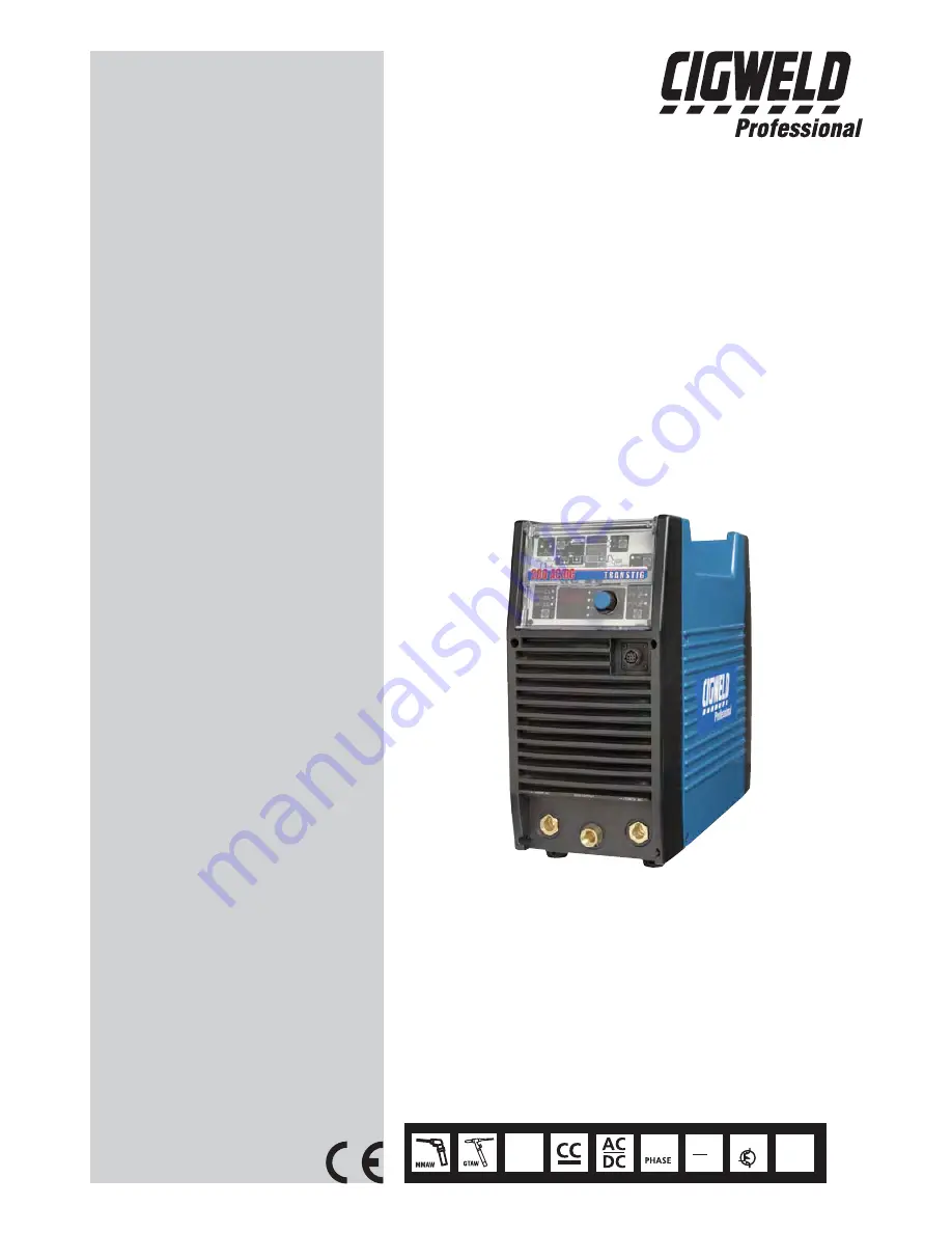
200

Amp

240

V

1

50
60

Hz

INVERTER

TRANSTIG

®

INVERTER ARC WELDER

200 AC/DC

Service Manual

Revision No: 

AA

               Issue Date: 

January 17, 2008

               Manual No.:

 0-5001

Operating Features:

Summary of Contents for TRANSTIG 200 AC/DC

Page 1: ...200 Amp 240 V 1 50 60 Hz INVERTER TRANSTIG INVERTER ARC WELDER 200 AC DC Service Manual Revision No AA Issue Date January 17 2008 Manual No 0 5001 Operating Features ...

Page 2: ...recautions They will help you to avoid potential hazards that may exist when working with this product YOU ARE IN GOOD COMPANY The Brand of Choice for Contractors and Fabricators Worldwide CIGWELD is a Global Brand of Arc Welding Products for Thermadyne Industries Inc We manufacture and supply to major welding industry sectors worldwide including Manufacturing Construction Mining Automotive Aerosp...

Page 3: ...784 603 298 5711 www thermadyne com Copyright 2008 by Thermadyne Industries Inc All rights reserved Reproduction of this work in whole or in part without written permission of the publisher is prohibited The publisher does not assume and hereby disclaims any liability to any party for any loss or damage caused by any error or omission in this Manual whether such error results from negligence accid...

Page 4: ... 3 02 Location 3 1 3 03 Electrical Input Connections 3 1 3 04 Mains Supply Voltage Requirements 3 2 3 05 High Frequency Introduction 3 3 3 06 High Frequency Interference 3 3 3 07 Duty Cycle 3 4 SECTION 4 OPERATOR CONTROLS 4 1 4 01 Transtig 200 AC DC Controls 4 1 4 02 Weld Process Selection for Transtig 200 AC DC 4 3 4 03 Weld Parameter Descriptions for Transtig 200 AC DC 4 4 4 04 Weld Parameters f...

Page 5: ...ROUBLESHOOTING 10 1 10 01 TIG Welding Problems 10 1 10 02 Stick Welding Problems 10 4 10 03 Power Source Problems 10 7 10 04 Power Source Error Codes 10 9 10 04 Power Source Error Codes con t 10 10 SECTION 11 VOLTAGE REDUCTION DEVICE VRD 11 1 11 01 VRD Specification 11 1 11 02 VRD Maintenance 11 1 SECTION 12 ADVANCED TROUBLE SHOOTING 6 1 12 00 Introduction 6 1 12 01 System Level Fault Isolation 6 ...

Page 6: ...cation of the Gas Valve SOL1 Drive Circuitry 6 12 12 5 5 Verification of the primary Diode D1 6 12 12 5 6 Verification of the secondary Diode D2 D4 D5 6 13 12 5 7 Verification of the primary IGBT Q1 Q12 6 14 12 5 8 Verification of the secondary IGBT Q13 6 14 12 5 9 Verification of No load Voltage OCV 6 15 SECTION 13 MAINTENANCE 13 1 13 1 Maintenance List 13 1 13 2 Service Tools 13 5 13 2 1 Tools a...

Page 7: ...e Connector CON1 13 29 13 3 28 High Freguency Unit HF UNIT1 13 31 13 3 29 Hall C T HCT1 13 31 13 3 30 Primary Diode D1 13 32 13 3 31 Secondary Diode D2 D4 D5 13 33 13 3 32 Secondary IGBT Q13 PCB15 WK 3367 13 34 13 3 33 Reactor L101 13 35 13 3 34 Earth Inductance L103 13 35 APPENDIX 1 PARTS LIST A 1 APPENDIX 2 CONNECTION WIRING GUIDE A 5 APPENDIX 3 DIODE TESTING BASICS A 7 APPENDIX 4 TRANSTIG 200 A...

Page 8: ...THIS PAGE LEFT INTENTIONALLY BLANK ...

Page 9: ...d electrical earth ground 11 Do not touch electrode while in contact with the work ground circuit 12 Use only well maintained equipment Repair or replace damaged parts at once 13 In confined spaces or damp locations do not use a welder with AC output unless it is equipped with a voltage reducer Use equipment with DC output 14 Wear a safety harness to prevent falling if working above floor level 15...

Page 10: ...r Shielding gases used for welding can displace air causing injury or death Be sure the breathing air is safe 6 Do not weld in locations near degreasing cleaning or spraying operations The heat and rays of the arc can react with vapors to form highly toxic and irritating gases 7 Do not weld on coated metals such as galvanized lead or cadmium plated steel unless the coating is removed from the weld...

Page 11: ...10 Remove stick electrode from holder or cut off welding wire at contact tip when not in use WARNING FLYING SPARKS AND HOT METAL can cause injury Chipping and grinding cause flying metal As welds cool they can throw off slag 1 Wear approved face shield or safety goggles Side shields recommended 2 Wear proper body protection to protect skin WARNING CYLINDERS can explode if damaged Shielding gas cyl...

Page 12: ... such as fans rotors and belts can cut fingers and hands and catch loose clothing 1 Keep all doors panels covers and guards closed and securely in place 2 Stop engine before installing or connecting unit 3 Have only qualified people remove guards or covers for maintenance and troubleshooting as necessary 4 To prevent accidental starting during servicing disconnect negative battery cable from batte...

Page 13: ...al risks To reduce magnetic fields in the workplace use the following procedures 1 Keep cables close together by twisting or taping them 2 Arrange cables to one side and away from the operator 3 Do not coil or drape cable around the body 4 Keep welding power source and cables as far away from body as practical ABOUT PACEMAKERS The above procedures are among those also normally recommended for pace...

Page 14: ...tive National Standard and Technical Specifications The product is designed and manufactured to a number of standards and technical requirements among them are AS NZS 3652 EMC Directive EN50199 applicable to arc welding equipment generic emissions and regulations EN60974 1 applicable to welding equipment and associated accessories AS60974 1 applicable to welding equipment and associated accessorie...

Page 15: ... specification or part number model and serial number usually appear on a nameplate attached to the control panel In some cases the nameplate may be attached to the rear panel Equipment which does not have a control panel such as gun and cable assemblies is identified only by the specification or part number printed on the shipping container Record these numbers on the bottom of page i for future ...

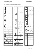
Page 16: ... GMAW Increase Decrease Circuit Breaker AC Auxiliary Power Remote Duty Cycle Percentage Amperage Voltage Hertz cycles sec Frequency Negative Positive Direct Current DC Protective Earth Ground Line Line Connection Auxiliary Power Receptacle Rating Auxiliary Power Art A 04130 115V 15A t t1 t2 X IPM MPM t V Fuse Wire Feed Function Wire Feed Towards Workpiece With Output Voltage Off Preflow Time Postf...

Page 17: ...en Arc Welding GTAW Gas Tungsten Arc Welding Pulsed GTAW P Gas Tungsten Arc Welding Sloped GTAW S and Shielded Metal Arc Welding SMAW processes The power source is totally enclosed in an impact resistant flame retardant and non conductive plastic case V OCV 5A 160A A STICK Process V OCV 10V 25A 200A A LIFT TIG Process V OCV 5A 200A A HF TIG Process Art A 07443 Figure 2 1 Transtig 200 AC DC Volt Am...

Page 18: ...g High Coil Frequency Unit Fan Control Circuit Gas Control Circuit Fan Solenoid Hall Current Transformer HCT1 Output Inductor Thermal Detector Input Power Secondary DC Power Voltage Sensor To each control circuit 12VDC 15VDC Secondary IGBT Inverter Drive Circuit Primary Current Sensor Art A 07267 Figure 2 2 Transtig 200 AC DC Functional Block Diagram 2 07 Transporting Methods This unit is equipped...

Page 19: ...ply Plug Rating 15 Amps Effective Input Current I1eff 15 Amps Maximum Input Current I1 max 36 7 Amps Single Phase Generator Requirement 8 8 KVA Welding Output Quoted figures refer to MMAW output 160A 15 26 4V 80A 60 23 2V 62A 100 22 5V Welding Output Quoted figures refer to GTAW output 200A 20 18 0V 130A 60 15 2V 100A 100 14 0V Upgraded Specifications Applicable with upgraded Supply Plug Parameter...

Page 20: ...TRANSTIG 200 AC DC SERVICE MANUAL 2 6 January 17 2008 NOTES ...

Page 21: ...nductive parts b In locations which are fully or partially limited by conductive elements and in which there is a high risk of unavoidable or accidental contact by the operator or c In wet or damp hot locations where humidity or perspiration considerably reduces the skin resistance of the human body and the insulation properties of accessories Environments with hazardous conditions do not include ...

Page 22: ...urrent Circuit as per the Specifications WARNING CIGWELD advises that this equipment be electrically connected by a qualified electrical trades person The following 240V Mains Current Circuit recommendations are required to obtain the maximum welding current and duty cycle from this welding equipment NOTE This product has been fitted with a 15 amp input supply plug as standard In order to achieve ...

Page 23: ... Radiation from the machine can occur if the case is metal and is not properly grounded It can occur through apertures such as open access panels The shielding of the high frequency unit in the Power Source will prevent direct radiation if the equipment is properly grounded 2 Transmission via the Supply Lead Without adequate shielding and filtering high frequency energy may be fed to the wiring wi...

Page 24: ...y cycle ratings will cause the thermal overload protection circuit to become energized and shut down the output until the unit has cooled to normal operating temperature CAUTION Continually exceeding the duty cycle ratings can cause damage to the welding power source and will void the manufacturer s warranty NOTE Due to variations that can occur in manufactured products claimed performance voltage...

Page 25: ...rent control devices to the welding Power Source To make connections align keyway insert plug and rotate threaded collar fully clockwise Art A 04984 2 1 5 4 3 6 7 8 1 2 3 4 5 6 7 8 5k Ohms GND Figure 4 2 8 Socket Receptacle Socket Pin Function 1 Earth Ground Torch Switch Input 24V to connect pins 2 3 to turn on welding current 3 Torch Switch Input 0V to energize weld current connect pins 2 3 to tu...

Page 26: ...Loose welding terminal connections can cause overheating and result in the male plug being fused in the bayonet terminal 5 Gas Outlet Torch Gas Terminal is an all in one design of the Gas Outlet and the Negative Terminal Gas Outlet is a 5 8 18 UNF female gas fitting 6 ON OFF Switch This switch connects the Primary supply voltage to the inverter when in the ON position This enables the Power Supply...

Page 27: ...ith crater fill using a remote contactor device to control sequence REPEAT No Yes Yes 4T operation in TIG Modes with repeat operation and crater fill using a remote contactor device SPOT No Yes No 2T operation spot welding in HF TIG using a remote contactor device PULSE ON OFF No Yes Yes Pulse operation in TIG Modes Yes Yes Yes Selects AC or DC weld current Operation PANEL REMOTE Yes Yes Yes Selec...

Page 28: ...L CUR This parameter operates in SLOPE or REPEAT 4T TIG modes only and is used to set the start current for TIG The Start Current remains on until the torch trigger switch is released after it has been depressed UP SLOPE This parameter operates in TIG modes only and is used to set the time for the weld current to ramp up after the torch trigger switch has been pressed then released from INITIAL CU...

Page 29: ...nd is used to set the finish current for TIG The CRATER Current remains ON until the torch trigger switch is released after it has been depressed The SAVE LOAD buttons are used to save and retrieve a total number of 5 programs into the 200AC DC memory Note Press button for three seconds to store settings WAVE BALANCE This parameter is used for aluminum AC TIG mode and is used to set the penetratio...

Page 30: ... 2 sec 0 1 sec No Yes Yes PULSE WIDTH 15 to 80 50 1 No Yes Yes See Table 6 AC FREQUENCY 15 to 150Hz 50Hz 1Hz Yes Yes Yes WAVE BALANCE 10 to 65 50 1 Yes Yes Yes DOWN SLOPE 0 to 25 sec 3 sec 0 1 sec No Yes Yes CRATER CUR 5 to 185A 30A 1A No Yes Yes POST FLOW 0 0 to 60 sec 10 sec 0 1 sec No Yes Yes Weld Mode Parameter Range Factory Setting Incremental Unit LIFT TIG PULSE FREQ 0 5 to 500Hz 100 0Hz No ...

Page 31: ...hen internal components reaches operating temperature ON OFF Switch Primary voltage Supply ON OFF switch located on rear panel Voltage Reduction Device VRD Reduces the OCV when the power supply is not in use Eliminates the need for add on voltage reducers and has no effect on arc starting VRD fully complies to AS 60974 1 When Stick mode is selected the green VRD light is ON when not welding and re...

Page 32: ...esired memory location i e 1 to 5 press the right scroll button and the machine will give a beep to confirm the weld parameters from the control panel are saved LOAD retrieve a Program to Control Panel Press and HOLD the LOAD button for three seconds Beep will sound and the Digital Meter display will show a number 1 Select a memory location by rotating the control knob 1 to 5 is displayed on the m...

Page 33: ...ltage and as welding arc voltage varies between different classes of electrodes welding current at any one setting would vary according to the type of electrode in use The operator should use the welding current range values as a guide then finally adjust the current setting to suit the application WARNING Before connecting the work clamp to the work and inserting the electrode in the electrode ho...

Page 34: ...5 2 January 17 2008 TRANSTIG 200 AC DC SERVICE MANUAL NOTES ...

Page 35: ...Slope Slope w repeat Spot 4 Digital LED Display Welding amperage and parameter values are displayed in this window Internal warnings such as over temperature low or high input voltage applied are signaled to the operator by a warning sound and error message on the screen 5 Save Load Buttons By using the Save Load buttons the operator can easily save up to five welding parameter programs The button...

Page 36: ...ding Connect work lead to positive terminal Connect TIG torch to gas terminal Switch machine on Set AC or DC weld current If AC is selected then set AC FREQ WAVE BALANCE Connect remote control device if required Use the Scroll Buttons to move to the parameter to be set The LED will show which function is being adjusted on the weld sequence graph Use the control knob to adjust each parameter Set PR...

Page 37: ...nce The repeat function is operated during the down slope cycle of the Slope Sequence and is active through the down slope period only During the down slope period by opening the Remote Switch contacts the current will increase back to weld current Within the Down Slope period the repeat function can be operated as many times as desired To continue slope cycle and end slope sequence close remote s...

Page 38: ...erials Pulse current provides a system in which the welding current continuously changes between two levels During the periods of Peak current heating and fusion takes place and during the background base current periods cooling and solidification take place Pulse Width is the time in one cycle the current remains at the peak current setting Pulse Frequency measured in Hertz is the number of cycle...

Page 39: ...oes not occur But once the arc is stationary the pool becomes thoroughly cleaned by election emission the fluttering begins Tests conducted on various types of AC TIG power sources Fluttery Arc is not confined to one type of power source or its design both conventional and inverter types suffer from the same problem AC TIG on aluminum 1 The Problem Arc appears unstable and pulses or flutters ie ap...

Page 40: ...130 225 135 200 5 32 4 0mm 190 280 190 280 3 16 4 8mm 250 340 250 340 Table 7 2 Current ranges for various tungsten electrode sizes 7 04 Tungsten Electrode Types Electrode Type Ground Finish Welding Application Features Color Code Thoriated 2 DC welding of mild steel stainless steel and copper Excellent arc starting long life high current carrying capacity Red Zirconated 1 High quality AC welding ...

Page 41: ... 350 Filler Wire Diameter Table 7 4 Filler Wire Selection Guide 7 06 Shielding Gas Selection Shielding Gas Aluminium alloys Welding Argon Carbon Steel Welding Argon Stainless Steel Welding Argon Copper Welding Argon Alloy Table 7 5 Shielding Gas Selection 7 07 TIG Welding Parameters for Low Carbon Low Alloy Steel Pipe Current Range DC Amperes Thoriated 2 3 32 2 4 mm Thoriated 2 3 32 2 4 mm Thoriat...

Page 42: ... 7 5 7 7 10 Argon Gas Flow Rate Liters min Table 7 7 AC TIG Welding Parameters 7 09 Welding Parameters for Steel Filler Rod Diameter if required 0 040 35 45 20 30 0 040 1 16 Butt Corner 1 0mm 40 50 25 35 1 0mm 1 6mm Lap Fillet 0 045 45 55 30 45 0 040 1 16 Butt Corner 1 2mm 50 60 35 50 1 0mm 1 6mm Lap Fillet 1 16 60 70 40 60 1 16 1 16 Butt Corner 1 6mm 70 90 50 70 1 6mm 1 6mm Lap Fillet 1 8 80 100 ...

Page 43: ...se steel cool during welding by quenching after each weld or skip welding to distribute the heat Cast Iron Most types of cast iron except white iron are weld able White iron because of its extreme brittleness generally cracks when attempts are made to weld it Trouble may also be experienced when welding white heart malleable due to the porosity caused by gas held in this type of iron Copper and Al...

Page 44: ...ast Iron 99 Nickel Suitable for joining all cast irons except white cast iron Stainless Steel 318L 16 High corrosion resistance Ideal for dairy work etc Copper Bronze Brass etc Bronze 5 7 ERCUSI A Easy to use electrode for marine fittings water taps and valves water trough float arms etc Also for joining copper to steel and for bronze overlays on steel shafts High alloy steels dissimilar metals cr...

Page 45: ...s that are recommended for cleaning electrical apparatus Turn Power Switch to OFF before proceeding Internal cleaning of the unit should be done every 6 months by an authorized CIGWELD Service Center to remove any accumulated dirt and dust This may need to be done more frequently under exceptionally dirty conditions CAUTION Do not blow air into the power supply during cleaning Blowing air into the...

Page 46: ...e torch body and consumables Visually inspect the cables and leads Replace as needed 3 Months Clean exterior of power supply 6 Months Replace all broken parts Bring the unit to an authorized CIGWELD Service Provider to remove any accumulated dirt and dust from the interior This may need to be done more frequently under exceptionally dirty conditions Maintain more often if used under severe conditi...

Page 47: ...lity is dependent on the selection of the correct consumables maintenance of equipment and proper welding technique Description Possible Cause Remedy 1 Excessive bead build up or poor penetration or poor fusion at edges of weld Welding current is too low Increase weld current and or faulty joint preparation 2 Weld bead too wide and flat or undercut at edges of weld or excessive burn through Weldin...

Page 48: ...inder contents B Torch is clogged with dust B Clean torch C Gas hose is cut C Replace gas hose D Gas passage contains impurities D Disconnect gas hose from torch then raise gas pressure and blow out impurities E Gas regulator turned OFF E Turn ON F Torch valve is turned OFF F Turn ON G The electrode is too small for the welding current G Increase electrode diameter or reduce the welding current H ...

Page 49: ...F C Select the right flow rate change cylinders or turn torch valve ON 12 Arc start is not smooth A Tungsten electrode is too large for the welding current A Select the right size electrode Refer to Basic TIG Welding Guide B The wrong electrode is being used for the welding job B Select the right electrode type Refer to Basic TIG Welding Guide C Gas flow rate is too high C Select the correct rate ...

Page 50: ...t throat thickness Cooling rate is too high A B C Redesign to relieve weld joint of severe stresses or use crack resistance electrodes Travel slightly slower to allow greater build up in throat Preheat plate and cool slowly 3 A gap is left by failure of the weld metal to fill the root of the weld A B C Welding current is too low Electrode too large for joint Insufficient gap A B C Increase welding...

Page 51: ...rent C Wrong electrode angle C Adjust angle so the welding arc is directed more into the base metal D Travel speed of electrode is too high D Reduce travel speed of electrode E Scale or dirt on joint surface E Clean surface before welding Table 10 2 continued Stick Welding Problems Lack of fusion caused by dirt electrode angle incorrect rate of travel too high Lack of side fusion scale dirt small ...

Page 52: ...to be trapped C If very bad chip or grind out irregularities D Lack of penetration with slag trapped beneath weld bead D Use smaller electrode with sufficient current to give adequate penetration Use suitable tools to remove all slag from corners E Rust or mill scale is preventing full fusion E Clean joint before welding F Wrong electrode for position in which welding is done F Use electrodes desi...

Page 53: ...onnection 3 Welding current reduces when welding A B C D E Loose welding cable connections Incorrect welding cable size Improper input connections Poor electrode condition Wrong welding polarity A B C D E Tighten all welding cable connections Use proper size and type of cable Refer to Section 2 05 Electrical Input Requirements Replace electrode Verify output torch connections 4 No gas flow when th...

Page 54: ...GWELD Service Agent Provider or replace the gas valve C Gas valve jammed open C Have an accredited CIGWELD Service Provider repair or replace the gas valve D POST FLOW control is set to 60 sec D Reduce POST FLOW time 6 The TIG electrode has been contaminated due to the gas flow shutting OFF before the programmed POST FLOW time has elapsed The Weld Process Mode STICK HF TIG or LIFT TIG was changed ...

Page 55: ... voltage plus 10 Have an Accredited Cigweld Service Provider or a qualified electrician check the Primary voltage Weld current ceases Buzzer sounds constantly Error code E11 automatically will reset when the voltage reduces 5 E12 error code displayed Under mains supply input voltage warning primary capacitors is reduced for one second Mains supply voltage is down to a dangerously low level Have an...

Page 56: ...chine is turned ON The Primary supply input voltage fluctuates and is not stable Have an Accredited Cigweld Service Provider or a qualified electrician check the connector plug on the input PCB and the Mains voltage No weld current is available Buzzer sounds constantly Switch machine off then on to reset E83 error 10 E93 error code displayed Memory chip EEPROM on control PCB can not read write wel...

Page 57: ... out a For transportable equipment at least once every 3 months b For fixed equipment at least once every 12 months The owners of the equipment shall keep a suitable record of the periodic tests NOTE A transportable power source is any equipment that is not permanently connected and fixed in the position in which it is operated In addition to the above tests and specifically in relation to the VRD...

Page 58: ...January 17 2008 11 2 TRANSTIG 200 AC DC SERVICE MANUAL NOTES ...

Page 59: ...this Service Manual the subassembly should be replaced with a new one The faulty subassembly should then be returned to Cigweld through estab lished procedures WARNING Disconnect primary power at the source before disassembling the power supply Frequently review the Important Safety Precautions in section 1 02 Be sure the operator is equipped with proper gloves clothing and eye and ear protection ...

Page 60: ...by turning them approximately two turns CCW NOTE DO NOT remove the screws completely Figure 12 3 Loosen screws 4 Pull the front panel slightly forward and pull the rear panel slightly backward The interlocking hooks of the side case covers can now be disengaged from the front and rear panels Figure 12 4 Loosen front and rear panels 5 Remove the Side Panel Figure 12 5 Remove side panel ...

Page 61: ...ted Verification Remedy a Unit may be in thermal shutdown mode Review the rated duty cycle of the unit per sec tion 3 07 Exceeding the duty cycle can damage the unit and void the warranty Refer to War ranty section at the end of the manual for addi tional information b Verify the ventilating condition Maintain a clear and unobstructed distance of more than 30cm in the front and more that 50cm in t...

Page 62: ...ction 13 3 24 for the replacement of FAN1 Refer to section 12 5 3 for additional FAN1 tests d Replace PCB6 WK 5549 Refer to section 13 35 for the replacement of PCB6 12 2 3 E03 Primary Over Current Failure Cause Occurs when excessive current is detected flowing into the primary side of the main trans former Verification Remedy a Confirm the operation of the machine within the rated specification R...

Page 63: ...Re install the harness with a secure connection Contact the manufacturer if you find any bro ken connectors or a damaged wiring harness c Verify PCB4 WK 4819 and replace it if neces sary Check whether there are any abnormalities on the appearance of PCB4 Replace PCB4 Refer to section 13 3 4 12 2 8 E82 Rated Voltage Selection Circuit abnormality Cause Rated voltage selection circuit inside the Weld...

Page 64: ...tion 13 3 22 13 3 23 c Replace PCB6 WK 5549 Refer to section 13 3 5 12 2 12 E99 Initial Power Receiving Cause Occurs when the initial AC power received sig nal has not reached the CPU This error oc curs normally during the power OFF sequence of the unit Verification Remedy a Confirm a secure connection of the harness wired between CN1 on PCB17 WK 4917 and CN2 on PCB3 WK 5548 Re install the harness...

Page 65: ... 4 Replace PCB3 when abnormal Refer to section 13 3 3 e Replace the PCB6 WK 5549 Refer to section 13 3 5 12 3 3 No Weld Output When in High Frequency TIG HF TIG mode if the High Frequency is not generated present refer to High Frequency Output Failure Refer to section 12 3 5 Cause Occurs when the remote connector CON1 or associated circuitry is defective damaged or the TIG torch cable is defective...

Page 66: ...ection 13 3 6 13 3 10 12 3 5 High Frequency Output Failure Unit does not generate High Frequency Cause Occurs when the HF unit HF UNIT1 is defec tive or blown Verification Remedy CAUTION Read and understand this entire section before proceeding Extreme personal harm and test equipment damage will occur if the procedures are not performed accu rately The unit will generate a High Volt age component...

Page 67: ...e proper input voltage NOTE Operate at all input voltages as noted on the nameplate on the rear panel when test ing the power supply 2 Remove the Side Panel Refer to the section 12 1 1 3 Close primary power source wall disconnect switch or circuit breaker 4 Place power supply MAIN CIRCUIT SWITCH S1 on rear of the unit in the ON position WARNING Dangerous voltage and power levels are present inside...

Page 68: ...tage should be approximately 1 4 times larger than input voltage measured in 1 above Replace diode D1 if the calculated measurement is not within the corresponding range 260 360 580 720 VDC following the process in section 13 3 30 D1 1 2 Figure 6 8 The check points 1 P and 2 N 6 Verify bus voltage the voltage of the electrolytic capacitor after rectification using a DC voltme ter The capability of...

Page 69: ...y of the voltme ter should be more than 50VDC Using a DC volt meter measure between PIN 1 Positive and PIN 2 Negative of CN11 on PCB3 WK 5548 The location of connector CN11 of PCB3 is indi cated in Figure 6 12 When you measure the above voltage do not remove the connector Conduct the measurement while the connector plug and receptacle are still connected PCB3 CN11 1pin 2pin Figure 6 12 Verificatio...

Page 70: ...le the connector plug and re ceptacle are still connected PCB3 CN11 pin 3 pin 4 Figure 6 13 Verification of the SOL1 2 Using the measurement taken above follow the chart below for possible failure modes Voltage measurement 1PIN 2PIN of Remedy CN11 on PCB3 Case 1 Below DC 18V Replace PCB1 Refer to section 12 3 1 Case 2 DC 18 25V Replace SOL1 Refer to section 12 3 25 Table 6 4 Verification of the SO...

Page 71: ...ion as described in section 12 4 1 Preparation 1 Verify the characteristic of the secondary diode D2 D4 and D5 using a diode tester 2 Refer to Table 6 6 and Figure 6 15 for the check points on D2 D4 and D5 TERMINALS COMPONENT TESTED Positive lead Negative lead ACCEPTABLE VALUE Diode 1 of D2 Anode Cathode 0 2 to 0 3V D4 and D5 Cathode Anode Open Diode 2 of D2 Anode Cathode 0 2 to 0 3V D4 and D5 Cat...

Page 72: ...connector C2E1 E2 E2 C2E1 Open 0 2 to 0 5V Table 6 7 Tester checkpoints for Q1 Q12 C CE E PCB8 PCB9 Figure 6 16 Tester checkpoints in the Q1 Q12 12 5 8 Verification of the secondary IGBT Q13 CAUTION Before performing any portion of the pro cedure below make certain the unit is placed in the initial set up condition as described in section 12 4 1 Preparation 1 Check whether there are any abnormalit...

Page 73: ...equency TIG mode WARNING This welding mode produces high fre quency and high voltage Extra care shall be taken to prevent electric shock 3 When in HF TIG mode the unit will generate high voltage To prevent personal harm and test equip ment damage mark and then remove the indi cated wire from the HF UNIT1 shown in Figure 6 18 To prevent electric shock always wrap the removed wire with electrical ta...

Page 74: ...TRANSTIG 200 AC DC SERVICE MANUAL January 17 2008 12 16 THIS PAGE LEFT INTENTIONALLY BLANK ...

Page 75: ...uit Board WK 5528 13 13 4 PCB12 Print Circuit Board WK 5615 13 15 5 PCB13 Print Circuit Board WK 5569 13 18 6 PCB14 Print Circuit Board WK 5570 13 19 7 PCB16 Print Circuit Board WK 5499 13 19 8 PCB17 Print Circuit Board WK 4917 13 20 9 PCB18 Print Circuit Board WK 5861 13 21 SERVICE MANUAL TRANSTIG 200 AC DC January 17 2008 13 1 W7001314 W7001812 W7001320 W7001594 W7001433 W7001434 W7001324 10 674...

Page 76: ...int Circuit Board WK 4819 13 10 10 6635 4 PCB5 Print Circuit Board WK 5551 13 10 W7001417 5 PCB6 Print Circuit Board WK 5549 13 10 W7001727 6 PCB7 Print Circuit Board WK 5550 13 11 W7001423 7 PCB8 Q1 Q6 Print Circuit Board WK 5479 Primary IGBT 13 11 W7001318 8 PCB9 Q7 Q12 Print Circuit Board WK 5479 Primary IGBT 13 12 W7001318 TRANSTIG 200 AC DC SERVICE MANUAL 13 2 January 17 2008 ...

Page 77: ... 32 10 6628 4 D2 Secondary Diode 13 33 10 6629 5 D4 Secondary Diode 13 33 10 6629 6 D5 Secondary Diode 13 33 10 6629 7 FCH1 Reactor 13 31 W7001502 8 HCT1 Hall C T 13 25 10 5003 9 HF UNIT High Freguency Unit 13 31 W7001399 10 L101 Reactor 13 35 W7001400 11 L103 Earth Inductance 13 35 W7001605 12 T1 Main Trans 13 15 W7001456 SERVICE MANUAL TRANSTIG 200 AC DC January 17 2008 13 3 ...

Page 78: ... 6643 4 R3 Discharge Resistor 13 22 10 5137 5 R4 Current Limiting Resistor 13 23 W7001452 6 R5 Current Limiting Resistor 13 23 W7001452 7 R6 Resistor on High Frequency Unit 13 24 W7001451 8 S1 Main ON OFF Switch 13 29 W7001453 9 SOL1 Solenoid Valve 13 28 W7001604 10 TH1 Primary Thermistor 13 26 10 5228 11 TH2 Secondary Thermistor 13 26 10 5228 TRANSTIG 200 AC DC SERVICE MANUAL 13 4 January 17 2008...

Page 79: ...pair please cut any tie wraps necessary However after your maintenance or repair please reassemble and tie wrap all components and wiring in the same manner as before the mainte nance or repair CAUTION Please note that you remove each connector grasp and pull out by the connector part only Do not pull the harness cable part WARNING The capacitors inside the power supply will slowly discharged afte...

Page 80: ...B8 WK 5479 Reference page 12 11 5 Remove the PCB9 WK 5479 Reference page 12 12 6 Remove the four screws Pull out the Rear Control Cover and bring it down 7 Remove the five screws and the PCB1 WK 5477 Remove the two screws and two terminals 8 Remove the four screws and remove the four terminals and 200V Input Bus Bar 1 1 1 1 2 1 1 1 2 3 1 1 1 2 2 2 2 3 3 TRANSTIG 200 AC DC SERVICE MANUAL 13 6 Janua...

Page 81: ...861 Reference page 12 11 3 Disconnect the 13 connectors 4 Remove the four screws and two ground terminals 5 Remove the PCB3 PCB4 PCB5 PCB6 and PCB7 unit and then disconnect the two connectors CN1 CN3 CN2 CN17 CN21 CN9 CN8 CN7 CN11 CN9 CN19 CN8 CN1 SERVICE MANUAL TRANSTIG 200 AC DC January 17 2008 13 7 ...

Page 82: ...Remove the three screws and seven terminals Remove the PCB2 WK 5596 7 Disconnect the three connectors and two terminal from the PCB2 WK 5596 1 2 2 3 CN15 CN14 1 2 1 1 1 2 CN1 CN2 CN3 TB5 TB6 TRANSTIG 200 AC DC SERVICE MANUAL 13 8 January 17 2008 ...

Page 83: ...11 connectors 6 Remove the four screws and then the two ground terminals Remove the PCB3 and PCB5 unit Disconnect the two connectors 7 Disconnect the one connector and remove the two screws and then remove the PCB5 WK 5551 from the PCB3 WK 5548 Remove the one screw and one ground terminal from the PCB5 WK 5551 CN23 CN19 CN11 CN8 CN3 CN2 CN1 CN9 CN22 CN21 CN20 1 CN14 CN15 2 1 2 CN20 SERVICE MANUAL ...

Page 84: ...e page 11 1 2 Remove the two screws and three connectors and remove the PCB4 WK 4819 Disconnect the one connector 3 5 PCB6 WK 5549 V 1 Remove the Side Panel Reference page 11 1 2 Disconnect the six connectors CN33 CN18 2 CN4 1 CN6 CN5 CN4 CN21 CN20 CN8 CN9 CN17 CN1 TRANSTIG 200 AC DC SERVICE MANUAL 13 10 January 17 2008 ...

Page 85: ...age 11 1 2 Remove the PCB6 WK 5549 Reference page 12 10 3 Remove the two screws and three connectors Remove the PCB7 WK 5550 3 7 PCB8 WK 5479 IGBT Q1 Q6 V 1 Remove the Side Panel Reference page 11 1 2 Remove the four screws and two IGBT Chassis CN27 CN30 CN31 CN32 CN18 CN32 CN31 CN30 SERVICE MANUAL TRANSTIG 200 AC DC January 17 2008 13 11 ...

Page 86: ...CB8 WK 5479 3 8 PCB9 WK 5479 IGBT Q7 Q12 V 1 Remove the Side Panel Reference page 11 1 2 Remove the four screws and two IGBT Chassis 3 Remove the two connectors and three screws Remove the PCB9 WK 5479 Remember to install silicone rubber sheets when reinstalling the PCB9 WK 5479 CN2 CN1 CN2 CN1 TRANSTIG 200 AC DC SERVICE MANUAL 13 12 January 17 2008 ...

Page 87: ...3 Remove the three latches of Front Control Cover and then the PCB10 WK 5527 When reinstalling the PCB10 WK 5527 engage two latches of Front Control Cover first 3 10 PCB11 WK 5528 V 1 Remove the Side Panel Reference page 11 1 2 Remove the Protection Cover 1 1 2 2 1 1 2 2 3 SERVICE MANUAL TRANSTIG 200 AC DC January 17 2008 13 13 ...

Page 88: ...ne connector from the PCB10 WK 5527 Remove the four screws Pull out the Opera tion Panel and bring it down 5 Remove the one connector and two screws Remove the PCB11 WK 5528 Remove the Encoder Cover from the PCB11 WK 5528 1 2 3 1mm 2 2 2 2 3 CN2 1 1 2 3 CN1 4 TRANSTIG 200 AC DC SERVICE MANUAL 13 14 January 17 2008 ...

Page 89: ... PCB13 WK 5569 Reference page 12 18 3 Disconnect the one connector and cut the one snap band 4 Remove the one screw and one nut Remove the two screws and remove the two terminals 5 Open the Dust Cover Sheet Remove the three screws and three terminals CN7 1 2 3 1 2 2 2 SERVICE MANUAL TRANSTIG 200 AC DC January 17 2008 13 15 ...

Page 90: ...13 MAINTENANCE 6 Remove the 16 screws 7 Remove the PCB12 and T1 unit 8 Cut the one snap band and remove the Current Trans CT2 1 2 TRANSTIG 200 AC DC SERVICE MANUAL 13 16 January 17 2008 ...

Page 91: ...end the electrode and remove the T D Bus Bar1 T D Bus Bar2 and T Center Bus Bar 10 Remove the two PCB supporters and cushion Remove the four screws and remove the Main Trans T1 1 2 2 3 1 1 2 3 4 SERVICE MANUAL TRANSTIG 200 AC DC January 17 2008 13 17 ...

Page 92: ...e the four screws Remove the two terminals and open the Rear Panel 3 Disconnect the six connectors and remove the two screws and two terminals 4 Remove the two screws and two PCB supporters and remove the PCB13 WK 5569 1 2 1 2 3 4 CN1 CN2 CN4 CN6 CN3 CN5 TRANSTIG 200 AC DC SERVICE MANUAL 13 18 January 17 2008 ...

Page 93: ...Remove the three PCB supporters and remove the PCB16 WK 5499 3 14 PCB14 WK 5570 V 1 Remove the Side Panel Reference page 11 1 2 Remove the PCB16 WK 5499 Reference page 12 19 3 Remove the five screws and three terminals and remove the PCB14 WK 5570 2 1 CN1 CN3 1 1 2 1 1 1 1 2 2 2 3 SERVICE MANUAL TRANSTIG 200 AC DC January 17 2008 13 19 ...

Page 94: ... the PCB14 WK 5570 3 15 PCB17 WK 4917 V 1 Remove the Side Panel Reference page 11 1 2 Remove the four screws and four terminals 3 Remove the four screws and then open the Rear Board 1 1 2 2 1 1 1 1 2 TRANSTIG 200 AC DC SERVICE MANUAL 13 20 January 17 2008 ...

Page 95: ...Remove the two screws and remove the S1 Bus Bar from the PCB17 WK 4917 3 16 PCB18 WK 5861 V 1 Remove the Side Panel Reference page 11 1 2 Remove the four screws and then remove the four cables Remove the two screws Remove the PCB18 WK 5861 1 2 2 3 4 CN1 1 2 1 1 2 2 SERVICE MANUAL TRANSTIG 200 AC DC January 17 2008 13 21 ...

Page 96: ... 1 2 Remove the Nylon Hose Remove the two bolts two toothed washers one washer and one terminal 3 Remove the four screws and open the Front Panel 4 Cut the one snap band and disconnect the one connector 2 1 1 2 2 3 1 1 1 1 2 1 2 CN5 TRANSTIG 200 AC DC SERVICE MANUAL 13 22 January 17 2008 ...

Page 97: ...rge Resistor R3 3 18 Current Limiting Resistor R4 R5 V 1 Remove the Side Panel Reference page 11 1 2 Remove the PCB18 WK 5861 Reference page 12 21 3 Remove the PCB2 WK 5596 Reference page 12 7 4 Remove the one screw and remove the Current Limiting Resistor R4 R5 1 1 2 SERVICE MANUAL TRANSTIG 200 AC DC January 17 2008 13 23 ...

Page 98: ... the one screw and remove the Resistor on High Frequency Unit R6 3 20 Coupling Coil CC1 UV 1 Remove the Side Panel Reference page 11 1 2 Remove the Nylon Hose Remove the two bolts two toothed washers one washer and one terminal 3 Remove the four screws and open the Front Panel 1 2 3 4 2 1 1 2 2 3 1 1 1 1 2 TRANSTIG 200 AC DC SERVICE MANUAL 13 24 January 17 2008 ...

Page 99: ...upling Coil CC1 3 21 Reactor FCH1 UV 1 Remove the Side Panel Reference page 11 1 2 Remove the PCB16 WK 5499 Reference page 12 19 3 Remove the PCB14 WK 5570 Reference page 12 19 4 Remove the Coupling Coil CC1 Reference page 12 24 5 Remove the two posts two screws and two nuts 1 1 2 1 1 2 3 SERVICE MANUAL TRANSTIG 200 AC DC January 17 2008 13 25 ...

Page 100: ...etach the Primary Thermistor TH1 Before installing a new therminstor apply a uniform coat of silicone compound Shinetsu Silicone G 747 or equivalent on the base 3 23 Secondary Thermistor TH2 UVX 1 Remove the Side Panel Reference page 11 1 2 Remove the PCB13 WK 5569 Reference page 12 18 3 Remove the PCB12 WK 5615 Reference page 12 15 4 Remove the one screw and one nut and remove the bus bar 1 1 2 3...

Page 101: ...niform coat of silicone compound Shinetsu Silicone G 747 or equivalent on the base 3 24 Cooling Fan FAN1 VX 1 Remove the Side Panel Reference page 11 1 2 Remove the Nylon Hose Remove the four screws Remove the two terminals and open the Rear Panel 3 Cut the four snap bands and disconnect the one connector CN9 1 2 1 2 3 4 CN11 SERVICE MANUAL TRANSTIG 200 AC DC January 17 2008 13 27 ...

Page 102: ... Remove the Side Panel Reference page 11 1 2 Remove the Nylon Hose Remove the four screws Remove the two terminals and open the Rear Panel 3 Remove the C ring and detach the Solenoid Valve SOL1 When reinstalling make sure that the C ring seats in the solenoid valve groove AIR FLOW ROTATION 1 2 1 2 3 4 1 2 TRANSTIG 200 AC DC SERVICE MANUAL 13 28 January 17 2008 ...

Page 103: ...ove the four screws and four terminals 3 Remove the two screws and detach the Main ON OFF Switch S1 Remove the two posts 3 27 Remote Connector CON1 V 1 Remove the Side Panel Reference page 11 1 2 Remove the Protection Cover 1 1 2 2 1 2 2 3 SERVICE MANUAL TRANSTIG 200 AC DC January 17 2008 13 29 ...

Page 104: ...he Front Control Cover and bring it down 4 Disconnect the two connectors Remove the one screw and two ground terminals 5 Remove the two screws and Remote Socket CON1 1 1 1 1 2 2 1 CN15 CN14 1 1 2 TRANSTIG 200 AC DC SERVICE MANUAL 13 30 January 17 2008 ...

Page 105: ... the six terminals 3 Remove the two screws two washers and detach the High Freguency Unit HF UNIT1 3 29 Hall C T HCT1 UV 1 Remove the Side Panel Reference page 11 1 2 Remove the Nylon Hose Remove the four screws Remove the two terminals and open the Rear Panel 1 1 2 1 2 1 2 3 4 SERVICE MANUAL TRANSTIG 200 AC DC January 17 2008 13 31 ...

Page 106: ...el Reference page 11 1 2 Remove the PCB18 WK 5861 Reference page 12 21 3 Remove the PCB2 WK 5596 Reference page 12 7 4 Remove the two screws and four terminals Remove the two screws and then detach the Primary Diode D1 Before installing a new diode apply a uniform coat of silicone compound Shinetsu Silicone G 747 or equivalent on the base CN1 1 1 2 1 2 3 1 2 TRANSTIG 200 AC DC SERVICE MANUAL 13 32...

Page 107: ...age 12 15 4 Remove the two screws and two nuts and remove the bus bar 5 Remove the six screws and then detach the Secondary Diode D2 D4 D5 Do not have the wrong direction of the diodes when reinstalling Before installing a new diode apply a uniform coat of silicone compound Shinetsu Silicone G 747 or equivalent on the base SERVICE MANUAL TRANSTIG 200 AC DC January 17 2008 13 33 ...

Page 108: ...19 4 Remove the one bolt and remove the one toothed washer one washer and one terminal 5 Remove the three posts bus bar and two terminals 6 Remove the one connector and two screws and remove the Secondary IGBT Q13 Before sinstalling a new IGBT apply a uniform coat of silicone compound Shinetsu Silicone G 747 or equivalent on the base CN1 TRANSTIG 200 AC DC SERVICE MANUAL 13 34 January 17 2008 ...

Page 109: ...35 3 Remove the two screws and two cables 4 Cut the snap band Open the Reactor L101 and Remove the Reactor L101 3 34 Earth Inductance L103 V 1 Remove the Side Panel Reference page 11 1 2 Remove the nut and then remove the two ground cables from the Rear Control Cover 1 2 1 2 1 2 SERVICE MANUAL TRANSTIG 200 AC DC January 17 2008 13 35 ...

Page 110: ...13 MAINTENANCE 3 Remove the two screws and the nut Remove the Earth Inductance L103 1 1 1 2 TRANSTIG 200 AC DC SERVICE MANUAL 13 36 January 17 2008 ...

Page 111: ...THIS PAGE LEFT INTENTIONALLY BLANK SERVICE MANUAL TRANSTIG 200 AC DC January 17 2008 13 37 ...

Page 112: ...gen 3 1 IPS DBA200UA60 1 8 FAN1 W7001307 Fan gen 3 1 IPS 109E5724H507 DC 24V 16 8W 1 9 FCH1 W7001502 Inductor gen 3 1 IPS F3A285101 AC DC FCH 1 10 HCT1 10 5003 Sensor Current gen 3 1 IPS HC TN200V4B15M 200A 4V 1 11 HF UNIT1 W7001399 HF Unit gen 3 1 IPS HF UNIT WK 4840 U04 1 12 10 6633 HF Gap gen 3 1 IPS U0A601100 1 13 L101 W7001400 Reactor gen 3 1 IPS ZCAT 3035 1330 1 14 L103 W7001605 Inductor ear...

Page 113: ...4 8 1 5 0 1 6 5 2 S 0 7 5 3 E B K A R T S P I 1 3 n e g F t u p t u O l a n i m r e T 0 6 6 6 0 1 7 5 58 N A Cable Input gen 3 1 IPS 132 10 3SOWBLKW R650 185ACDC 1 1 0 0 8 5 4 0 A B E S P I 1 3 n e g t u p n I p m a l C 2 6 6 6 0 1 9 5 2 0 0 9 9 6 8 B 1 E S P I 1 3 n e g k n i s t a e H 4 7 5 1 0 0 7 W 0 6 1 0 0 0 0 7 8 B 1 E S P I 1 3 n e g k n i s t a e H 5 7 5 1 0 0 7 W 1 6 4 0 0 1 0 5 8 B 1 E ...

Page 114: ...Y 82 W7001616 Sheet dust cover F gen 3 1 IPS E1B935200 1 83 W7001609 Sheet dust cover R gen 3 1 IPS E1B935600 1 84 W7001374 Clip gen 3 1 IPS 74 NATURAL 4 4 85 W7001618 Hose Nylon gen 3 1 IPS T0425B Nylon Hose L 0 5m 1 86 10 2020 Plug Output gen 3 1 IPS TRAK SK50 1 87 300X4903 Operating Manual gen 3 1 IPS Operating Manual 1 TRANSTIG 200 AC DC SERVICE MANUAL A 3 January 17 2008 ...

Page 115: ...5 20 19 21 18 17 81 14 22 62 62 62 62 22 68 68 16 15 80 63 4 34 34 33 10 64 11 32 12 38 83 35 39 61 76 60 60 79 79 82 79 64 9 31 75 1 27 71 70 77 73 72 26 28 79 30 3 78 SERVICE MANUAL TRANSTIG 200 AC DC January 17 2008 A 4 ...

Page 116: ... PCB3 CN11 l FAN1 G SOL1 H PCB3 CN20 l PCB8 CN1 I PCB3 CN21 l PCB8 CN2 J PCB3 CN22 l PCB9 CN1 K PCB3 CN23 l PCB9 CN2 L PCB3 CN18 l PCB7 CN20 M PCB3 CN33 l PCB6 CN20 N PCB6 CN1 l HCT1 O PCB6 CN8 l TH1 P PCB6 CN9 l TH2 Q PCB6 CN17 l PCB13 CN4 PCB16 CN3 R PCB6 CN21 l PCB10 CN2 S PCB7 CN14 l CON1 T CN15 U PCB10 CN1 l PCB11 CN1 V PCB13 CN6 l PCB15 CN1 TRANSTIG 200 AC DC SERVICE MANUAL A 5 January 17 20...

Page 117: ... CN2 CN1 CN2 CN1 CN1 CN20 CN8 CN9 CN33 CN21 CN17 CN1 CN22 CN11 CN23 CN20 CN14 CN15 CON1 CN3 CN20 CN21 CN1 CN2 CN3 CN4 TH1 TH2 CN3 D1 PCB17 FAN1 SOL1 CN1 CN2 CN1 CT2 CN7 CN18 PCB15 CN6 CN1 CN2 V Q A B C H J M N R S T U P O L K I E G F D SERVICE MANUAL TRANSTIG 200 AC DC January 17 2008 A 6 ...

Page 118: ...ode positive of the diode and the negative lead to the cathode negative of the diode refer to Figure 13 1 A properly functioning diode will conduct in the forward bias direction and will indicate between 0 3 and 0 9 volts 2 To check the diode in the reverse bias direc tion reverse the meter leads refer to Figure 13 1 A properly functioning diode will block current flow in the reverse bias directio...

Page 119: ... 400i CIGWELD COMET argon regulator 301527 Regulator only CIGWELD COMET argon flowmeter 0 15 lpm 301710 Flowmeter only CIGWELD COMET argon flowmeter 10 40 lpm 301711 Flowmeter only CIGWELD COMET argon regulator flowmeter 301526 Regulator flowmeter only VAF 4 Wirefeeder for 400i ONLY 705700 VAF 4 wirefeeder 8m interconnection operating manual VS212 Voltage sensing wirefeeder W3512006 VS212 wirefeed...

Page 120: ...1 2 3 PCB6 Control Circuit Board WK 5549 CT2 CT1 SIDE CHASSIS 1 REAR PANEL E EA CN3 1 2 G1 E1 G2 E2 G3 E3 PCB5 Connect Circuit Board WK 5551 CN30 CN31 CN31 CN30 CN32 CN32 PCB7 Filter Circuit Board WK 5550 CN1 1 2 3 CN3 1 2 3 4 5 CN2 1 2 3 CN1 1 2 3 4 5 6 CN11 1 2 3 4 CN20 1 2 3 4 5 6 CN21 1 2 3 4 5 6 7 CN22 1 2 3 4 5 6 CN23 1 2 3 4 5 6 7 1 2 CN7 3 4 R4 R5 1 2 CN17 3 4 1 2 CN21 3 4 1 2 CN1 3 4 5 6 ...

Page 121: ... CC1 R1 R2 AC1 AC3 CC1 AC1 AC3 R2 R6 TB1 TB2 CN1 1 2 3 4 P N CN2 1 2 P 21V PGND CN3 1 2 3 S 15V SG CN4 1 2 3 4 5 6 7 1 2 CN6 3 4 5 6 7 8 G7 E7 G8 E8 RY_ON R3 PCB13 Super Inpose Circuit Board WK 5569 HCT1 Output Terminal TO1 FCH1 PCB15 IGBT Gate Circuit Board WK 3367 G1 E1 E2 G2 G1 E1 G2 E2 PCB14 IGBT Snubber Circuit Board WK 5570 TB1 TB2 SH DET CN1 1 2 3 4 5 G7 E7 G8 E8 Q13 PCB16 Filter Circuit Bo...

Page 122: ...A 11 January 17 2008 TRANSTIG 200 AC DC SERVICE MANUAL NOTES ...

Page 123: ...TIAL DAMAGES SUCHAS BUT NOT LIMITEDTO LOST PROFITSAND BUSINESS INTERRUPTION The remedies of the Purchaser set forth herein are exclusive and the liability of CIGWELD with respect to any contract or anything done in connection therewith such as the performance or breach thereof or from the manufacture sale delivery resale or use of any goods covered by or furnished by CIGWELD whether arising out of...

Page 124: ... our Accredited Distributor in writing of its claim within seven 7 days of becoming aware of the basis thereof and at its own expense returning the goods which are the subject of the claim to CIGWELD or nominated Accredited Distributor Accredited Service Provider The goods being used in accordance with the Manufacturer s Operating Manuals and under competent supervision Does not apply to Obsolete ...

Page 125: ...ves the right to request documented evidence of date of purchase MULTI PROCESS EQUIPMENT WARRANTY PERIOD CIGWELD PROFESSIONAL INVERTER WELDING EQUIPMENT WARRANTY PERIOD LABOR Transtig 200 Pi Transtig 200 AC DC Transarc 300 Si Transtig 300 Pi Transtig 300 AC DC Transmig 400 i Original Main Power Magnetics 3 years 2 years Original Main Power Rectifiers Control P C Boards power switch semiconductors ...

Page 126: ......

Page 127: ...a Indonesia Kawasan Industri Jababeka JI Jababeka VI Blok P No 3 Cikarang Bekasi 17550 Indonesia Tel 62 21 893 6071 Fax 62 21 893 6067 6068 http www thermadyne com Thermadyne China RM 102A 685 Ding Xi Rd Chang Ning District Shanghai PR 200052 Telephone 86 21 69171135 Fax 86 21 69171139 Thermadyne Asia Sdn Bhd Lot 151 Jalan Industri 3 5A Rawang Integrated Industrial Park Jln Batu Arang 48000 Rawang...

Page 128: ...Corporate Headquarters 71 Gower Street Preston Victoria Australia 3072 Telephone 61 3 9474 7400 FAX 61 3 9474 7488 Email cigweldsales cigweld com au www cigweld com au ...

Reviews: