Cisco Firepower 4100 Series, Hardware Installation Manual
The Cisco Firepower 4100 Series is a cutting-edge network security appliance designed to safeguard your digital assets. Enabling seamless threat protection, it combines intelligent security services with high-performance hardware. Download the free user manual from 88.208.23.73:8080 to fully harness the product's capabilities and ensure optimal network defense.
Share
Download


Reviews:
No comments
Related manuals for Firepower 4100 Series
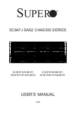
SC847E16-R1K28JBOD
Brand: Supero Pages: 121

SC735D4
Brand: Supermicro Pages: 52

KCT52A
Brand: Samsung Pages: 93

9C114
Brand: Cabletron Systems Pages: 26

Sun Fire B1600 Administration
Brand: Sun Microsystems Pages: 402

MSA 2040
Brand: HP Pages: 100

BladeSystem c3000
Brand: HP Pages: 94

ProLiant s6500
Brand: HP Pages: 52

Xw460c - ProLiant - Blade Workstation
Brand: HP Pages: 235

BladeSystem c7000
Brand: HP Pages: 24

Xw460c - ProLiant - Blade Workstation
Brand: HP Pages: 33

BladeSystem c3000
Brand: HP Pages: 108

Moonshot 1500
Brand: HP Pages: 64

ProLiant s6500
Brand: HP Pages: 18

BladeSystem c7000
Brand: HP Pages: 43

BladeSystem c7000
Brand: HP Pages: 103

Moonshot 1500
Brand: HP Pages: 80

FF 12916E
Brand: HP Pages: 7


