background image

Quick Start Guide for Cisco NCS 1001

Summary of Contents for NCS 1001

Page 1: ...Quick Start Guide for Cisco NCS 1001 ...

Page 2: ...NCS1K EDFA and a Protection Switching Module NCS1K PSM can be inserted in these slots The optical modules can be inserted in slots 1 to 3 as shown in the following figure The optical modules can be inserted and removed from the slots while the system is operational In amplified configuration the Optical Amplifier module can be inserted in any slot In section protected configuration the protect Opt...

Page 3: ...fety and system cooling compliance See Figure 1 Cisco NCS 1001 Front View on page 3 and Figure 3 Cisco NCS 1001 Rear View on page 4 to identify the slots for optical modules and PSUs respectively Caution Figure 1 Cisco NCS 1001 Front View Optical Module Slot 1 1 Optical Module Slot 2 2 Optical Module Slot 3 3 3 ...

Page 4: ...0 ports and one UDC for optical module 3 2 Two USB 2 0 ports and one 10 100 1000 LAN electrical management interface 3 10 100 1000 LAN management interface optical 4 Status LED SFP link Power supply Fan System Beacon OIR 5 RS232 console port of the control card 6 OIR switch 7 Figure 3 Cisco NCS 1001 Rear View Control card and SSD Solid State Disk 1 Fan 3 2 4 ...

Page 5: ...e and higher order modulation format transponders Switchable gain pre amplifier up to 34db Embedded Optical Channel Monitoring OCM module to monitor per channel power at all the input and output ports Integrated pluggable optics based OSC and OTDR support OSC supports user data channel transport as well as remote node management Supports 96 channels of C Band in 1 RU Supports flex grid on OCM modu...

Page 6: ...stics Width 17 44 442 9 mm Depth 23 64 600 5 mm Height 1 RU Weight without power supply unit 8 2 kg Weight with two power supply units 10 5 kg Weight of AC PSU 1 162 kg Weight of Fan 78 gms Weight of control card 1 5 kg 6 ...

Page 7: ...ion Off The SFP link is up Green SFP The link is down active alarms are present on this port or a hardware failure has occurred Yellow The port is not provisioned by the software the optics module is missing or the port does not have power Off The unit is operating correctly Green PSU and FAN The unit has one or more errors detected Red The control card is not present or not properly inserted Red ...

Page 8: ...Revised April 13 2018 Review Safety Warnings Review the safety warnings available at Regulatory Compliance and Safety Information for Cisco NCS 1000 Series 8 ...

Page 9: ...ed for installation Step 3 To remove the shelf grasp the side of the shelf and lift the shelf out of the box Step 4 Verify that you have all items Step 5 Verify the following Cisco NCS 1001 is not damaged The cable connectors management ports console ports and power connectors are not damaged The SFP cages on the front panel are not damaged Verify that outstanding scratch mark bend discoloration o...

Page 10: ...Caution It is required to have 100 mm 3 94 space on the front and rear side of the rack to provide sufficient clearance for cable routing and cooling of the system In case of a closed cabinet the cabinet must support the thermal management or front rear doors need to have 70 perforation Closed cabinets must have adequate airflow to dissipate maximum power from equipments in a fully equipped cabine...

Page 11: ...e chassis using the screws 48 0471 01 and 48 2406 01 and tighten them to a torque value of 0 65 N m 5 9 in lbs for 48 0471 01 screws and torque value of 1 5 N m 13 25 in lbs for 48 2406 01 screws Figure 5 Sliding Edge Sliding edge 1 Screws for sliding edge part number 48 0471 01 2 The edge always need to be facing bottom side on both the sides 3 11 ...

Page 12: ... Right L Bracket 1 Screws for L Bracket part number 48 2406 01 2 Left L Bracket 3 Step 3 Fix the Grounding extender to the chassis with the screws 48 1142 01 and tighten them to a torque value of 2 5 3 4 N m 22 0 30 0 in lbs 12 ...

Page 13: ...de as per the figure Grounding extender 1 Extender screws part number 48 1142 01 2 Step 4 Install four post slider or two post slider as required a Install Four Post Slider into EIA ANSI Rack on page 16 b Install Two Post Slider into EIA ANSI Rack on page 22 Step 5 Insert the chassis onto the sliding rail assembled on the two or four post 19 or 23 rack 13 ...

Page 14: ...he empty chassis to the rack for easy handling Figure 8 NCS 1001 Chassis Assembly into Two or Four Post 19 or 23 Rack Ground lug extender must be assembled before inserting the chassis See Figure 7 Grounding Extender on page 13 1 14 ...

Page 15: ...mber 48 101524 01 3 Step 6 As soon as the chassis is completely inserted fasten the chassis with two screws 48 101524 01 on each side of the bracket and tighten them to a torque value of 3 4 N m 30 in lbs The sliding rail must be used only during the first mounting process and it serves only to push the chassis into the rack and not for sliding purpose The chassis must be fixed with screws on the ...

Page 16: ...I Rack Procedure Step 1 Identify the four post slider Figure 9 Four Post Slider Identification Check for the left right marking on the sliders This is left front sliding rail 1 Check for the left right marking on the sliders This is left rear sliding rail 2 16 ...

Page 17: ...re 10 Four Post Slider Preparation Align the sliders left front left rear or right front right rear as shown 1 Flange facing side during assembly 2 Once the shoulder rivets are aligned slide in the sliders as shown in the arrow mark SLIDE 17 ...

Page 18: ...e the slider to the four post 19 rack Figure 11 Slider Integration to the Four Post 19 Rack Left side four post slide assembly 1 Right side four post slide assembly 2 Slider fixing screws part number 48 101524 01 3 18 ...

Page 19: ...e of the 19 rack and the inner surface of the sliding rail are properly mated while assembling the sliding rail Note Figure 12 Mating for the Four Post 19 Rack Edge surface of the rack 1 Inner surface of the sliding bracket 2 19 ...

Page 20: ...ate the slider to the four post 23 rack Figure 13 Slider Integration to the Four Post 23 Rack The formed surface must always face the inner side of the rack post 1 Slider fixing screws part number 48 101524 01 2 20 ...

Page 21: ...urface of the adapter and the inner surface of the sliding rail are properly mated while assembling the sliding rail Note Figure 14 Mating for the Four Post 23 Rack Edge surface of the adapter 1 Inner surface of the sliding bracket 2 21 ...

Page 22: ...IA ANSI Rack Procedure Step 1 Identify the two post slider Figure 15 Two Post Slider Identification Check for the left right marking on the sliders 1 a Check whether the two post width is 5 OR 3 If the width is 5 use the default slider assembly for 5 22 ...

Page 23: ...der Preparation Align the rivet with key hole 2 Do not insert any rivet inside this 3 a Unfasten the 4X screws as shown above b Align the shoulder rivet with the key hole as shown c Fasten all the 4X screws again The two post slider is ready to use on 3 width post This assembly procedure is the same for right or left sliders 23 ...

Page 24: ...Step 3 Integrate the slider to the two post 19 rack Figure 17 Slider Integration to the Two Post 19 Rack 24 ...

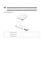
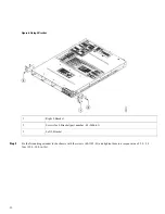
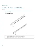
Page 25: ...Left side four post slide assembly 1 25 ...

Page 26: ...r 48 101524 01 3 Ensure that the edge surface of the 19 rack and the inner surface of the sliding rail are properly mated while assembling the sliding rail Note Figure 18 Mating for the Two Post 19 Rack Edge surface of the rack 1 Inner surface of the sliding bracket 2 26 ...

Page 27: ...rate the slider to the two post 23 rack Figure 19 Slider Integration to the Two Post 23 Rack The formed surface must always face the inner side of the rack post 1 Slider fixing screws part number 48 101524 01 2 27 ...

Page 28: ...surface of the adapter and the inner surface of the sliding rail are properly mated while assembling the sliding rail Note Figure 20 Mating for the Two Post 23 Rack Edge surface of the adapter 1 Inner surface of the sliding bracket 2 28 ...

Page 29: ...t Clean the mating surfaces and apply appropriate antioxidant compound to the bare conductors Step 3 Attach one end of the shelf ground cable 8 AWG cable to the ground point using the specified dual hole lug connector See Figure 7 Grounding Extender on page 13 Figure 21 NCS 1001 Ground Lug The orientation of the lug cable is always at the bottom side Ground lug 1 Star washer part number 48 1354 01...

Page 30: ...30 ...

Page 31: ... inserted in the chassis to support all the features and provide power to all the pluggable modules When only one PSU is inserted in the chassis the Power Module Redundancy Lost major alarm is raised In case of single PSU the other PSU slot must be inserted with the PSU filler module to guarantee safety and system cooling compliance Caution ...

Page 32: ...ween 200 V to 240 V or between 100 V to 127 V depending on the standards in various countries A dual pole breaker is needed for the installation The rating of the dual pole breaker is 16A for International and 20A for USA and Canada Note Figure 22 Hot Area on PSU Faceplate Procedure Step 1 Verify that the AC cable is installed in the correct AC source panel Ensure that either the fuse is removed o...

Page 33: ...Step 2 Attach the AC power cable to the cable connector in the AC power module Step 3 Close the cable clamp to secure the power cable Figure 23 Connecting AC Power 33 ...

Page 34: ...34 ...

Page 35: ...er cord 1 Cable clamp 2 Tie mount 3 Final assembly 4 Step 4 Ensure that the lockout device is removed if installed and turn on the circuit breaker s to the shelf Verify that the Green LED on the PSU is on 35 ...

Page 36: ... ground faults Ensure that the protective devices comply with local and national electrical codes Caution The system accepts a nominal input voltage of 48 VDC or 60 VDC at 15A with an operational tolerance range of 40 5 to 72 VDC A dual pole breaker per each power feed is needed for the installation The rating of the breaker is 20A Figure 24 Hot Area on PSU Faceplate 36 ...

Page 37: ...er according to local practice Step 4 Connect the office battery and return cables according to the fuse panel engineering specifications Step 5 Insert the DC connector into the DC receptacle on the power supply Figure 25 Connecting DC Power DC Power Cord 1 Step 6 Ensure that either the fuse is inserted or the circuit breaker is in the ON position Verify that the Green LED on the PSU is on 37 ...

Page 38: ...Revised April 13 2018 Related Information For more information on NCS 1001 including specifications see the data sheet 38 ...

Page 39: ... 2018 Cisco Systems Inc All rights reserved ...

Page 40: ...coSystemsInternationalBV Amsterdam TheNetherlands CiscoSystems USA Pte Ltd Singapore Cisco Systems Inc San Jose CA 95134 1706 USA Cisco has more than 200 offices worldwide Addresses phone numbers and fax numbers are listed on the Cisco Website at www cisco com go offices ...

Reviews: