Clavister SC6300 Series, Installation And Setup Manual
The Clavister SC6300 Series is a high-performance network security platform designed to safeguard your network infrastructure. For a hassle-free installation and setup, we provide a comprehensive Installation and Setup Manual. Download this manual for free from our website and unleash the full potential of your Clavister SC6300 Series.
Share
Download


Reviews:
No comments
Related manuals for SC6300 Series

GEN8 P.A.C.K.
Brand: REDCAT Pages: 24

LC1.15E
Brand: Philips Pages: 24

L04E AD
Brand: Philips Pages: 28

L01H.1A
Brand: Philips Pages: 74

L04LAA
Brand: Philips Pages: 94

L9.1A
Brand: Philips Pages: 113

L9.2E AA
Brand: Philips Pages: 122

ARX 6000
Brand: F5 Pages: 104

TXP5016
Brand: THORLABS Pages: 44
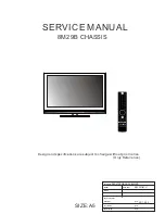
8M29B
Brand: Skyworth Pages: 45
8M26S
Brand: Skyworth Pages: 57

C147
Brand: Travla Pages: 2

PXIe-1086
Brand: National Instruments Pages: 16

Cobra IW-RS212-07
Brand: InWin Pages: 29


