
TM
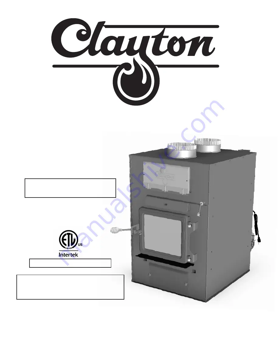
This manual includes Installation and
operation instructions for the Model
CF700M Furnace utilizing the listed
operational types:
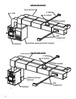
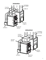
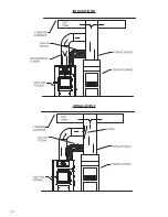
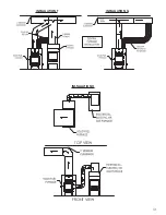
1. Wood add-on
2. Wood only
Owner’s Installation and Operation Manual
Model CF700M
Installation is to be preformed by a
qualified installer.
SAVE THESE INSTRUCTIONS
This unit is certified UL 391
United States Stove Company
227 Industrial Park Rd.
South Pittsburg, TN 37380
852511-0804F
U.S. ENVIRONMENTAL PROTECTION AGENCY
Certified to comply with the 2016 particulate
emission standards. Not approved for sale after
May 15, 2020


