background image


15/05/2020 


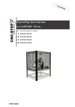
Operating Instructions 


AceroDURO Series 


Rev. 05/2020 (Subject to Change) 


  50 /S25/S50/S75/S100 

100 /S25/S50/S75/S100


150 /S25/S50/S75/S100


200 /S25/S50/S75/S100


https://www.cnc-step.com/ 


Summary of Contents for AceroDURO 100/S100

Page 1: ...15 05 2020 Operating Instructions AceroDURO Series Rev 05 2020 Subject to Change 50 S25 S50 S75 S100 100 S25 S50 S75 S100 150 S25 S50 S75 S100 200 S25 S50 S75 S100 https www cnc step com ...

Page 2: ...complete mechanics for a three dimensional movement The linear carriage movement takes place via threaded spindles powered by step motors Depending on size one or two drives are used on the X axis The activation of the step motors in order to operate every single axis is done by using further interfaces This operating description will show you how to install operate and service this CNC portal sys...

Page 3: ... fire 13 2 2 5 Radiation hazards 14 2 2 6 Hazards of chemicals 14 2 2 7 General work related dangers 16 2 3 Responsibility of the operator 17 2 4 Staff requirements 18 2 4 1 Qualification 18 2 4 2 Instruction 19 2 5 Personal protective equipment 19 2 6 Safety installations 21 2 6 1 Description of the installed safety installations 21 2 6 2 Safety installations which must be updated by the owning o...

Page 4: ... 3 1 Z axis with carriage 37 4 3 2 Y axis with carriage 38 4 3 3 X axis with carriage 39 4 3 4 Tool holder 40 4 4 Controls 41 4 5 Connections 41 4 5 1 Control signals ST 42 4 5 2 Motor connector X1 X2 Y Z 43 4 5 3 MiniXLR pin socket Pin15 43 4 6 Work and danger areas 45 4 6 1 Working area 45 4 6 2 Danger zone 45 5 TRANSPORT PACKAGING AND STORAGE 46 5 1 Safety instructions for transport 46 5 2 Tran...

Page 5: ...ies during operation 59 7 4 1 Operating machine 59 7 4 2 Change tool 62 7 5 Switching off 62 7 6 Activities after use 63 7 7 Emergency Shutdown 63 8 MAINTENANCE 65 8 1 Safety Instructions for maintenance 65 8 2 Spare parts 66 8 3 Maintenance Schedule 67 8 4 Maintenance 68 8 4 1 Cleaning of the machine 68 8 4 2 Lubricate machine 69 8 5 Measures after maintenance 75 9 FAILURES 76 9 1 Cautions for Tr...

Page 6: ...8 Geldern Germany Page 6 Support 49 0 2831 91021 50 15 05 2020 10 DISMANTLING AND DISPOSAL 82 10 1 Safety regulations for the disassembling and disposal 82 10 2 Disassembling 82 10 3 Disposal 83 11 APPENDIX 84 11 1 Accessories 84 12 CUSTOMER SERVICE 85 12 1 Remote maintenance 86 ...

Page 7: ...l are intended to facilitate basic understanding and may differ from the actual design Further guidelines regarding built in components are found in the appendix of this description 1 1 Symbol description Safety instructions are designated by symbols In addition there is always a signal word heading the information indicating the severity of the danger or hazard that may be encountered NOTE Indica...

Page 8: ...structions Used other than for the intended purpose Unauthorized or unapproved personnel Unauthorised rebuilds or modifications Unauthorized technical changes The use of unauthorized replacement parts or non original accessories The actual scope of delivery can by special designs deviate from the explanations and presentations given here because of the utilization of additional order options or be...

Page 9: ...er concerning operation servicing and maintenance Every application in excess of the intended use and or other use can lead to hazardous situations and is considered misuse WARNING Danger due to misuse Improper use of the CNC portal machine can cause dangerous situations Operation outside the values specified in the section Technical data Bypassing the safety devices Remodelling refitting or chang...

Page 10: ...vidual components can mean danger to life Any work required at the electrical system may only be carried out by a qualified electrician in compliance with electro technical regulations In case of damage to the insulation switch off the power supply immediately and have repairs carried out Before starting to work on active parts of electrical systems and equipment establish a voltage free state thr...

Page 11: ...ling spindles can lead to severe personal injury or material damage Before the start of any work ensure that all covers and protective devices are correctly installed and function correctly Never touch moving tool during operating process Before exchanging tools always pull power plug of the milling motor or turn off the machine and secure against restarting Axis motion WARNING Risk of injury by a...

Page 12: ...s Unexpected start up of the machine WARNING Risk of injury caused by unexpected start up of the machine The machine and the used tools can start up unexpectedly change their direction or stop Limbs can get trapped It must be ensured that no body parts interact with the danger zone of the machine Protect working area against unintentional access Keep protective devices closed and operational at al...

Page 13: ... for all tasks with tools work pieces and chips heat resistant clothing and gloves must be worn Before all tasks make sure that all surfaces have cooled down to the ambient temperature 2 2 4 Risk of fire Highly flammable materials ATTENTION Risk of fire by highly flammable materials Organic dust produced by coal or wood or inorganic dust from magnesium aluminium zinc or titanium can catch fire and...

Page 14: ...l metal objects Jewellery watches pens etc before starting maintenance operation No electronic equipment is to be taken near the magnetic source area These could get damaged No storage media credit cards etc are to be taken into the magnetic source area Containing data may be deleted 2 2 6 Hazards of chemicals Cooling emulsion WARNING Danger of serious damage to health by polluted cooling emulsion...

Page 15: ...oling emulsion may lead to health risks Avoid contact with your skin Remove cooling emulsion from the skin immediately Do not inhale the vapours Adhere to Manufacturers instructions Oil and fat ATTENTION Risk of health due contacting with oil and fat Contact with oil and fat may lead to health risks Avoid skin contact Remove oil and fat immediately from skin Do not inhale vapours Adhere to Manufac...

Page 16: ...area when required Take measures to reduce noise such as changing cutting data or changing the way of clamping your workpiece Dirt and objects lying around Attention Risk of tripping by dirt and objects lying around Soiling and objects left lying around are sources of slipping and stumbling and can cause considerable injuries Always keep the work area clean Remove any objects which are no longer r...

Page 17: ...hrough the special working conditions at the place of operating the machine He must implement this in the form of operating instructions for the operation of the machine During the complete usage time of the machine the owner must check whether the operating instructions created by him correspond with the current status of the regulations and must adapt them if necessary The owner must clearly reg...

Page 18: ...lcohol or medicines are not authorized In this instruction all required qualifications for the different people with different tasks are named Operator The operator was instructed by the operating company in a briefing about the tasks assigned to them and instructed about possible hazards because of improper conduct The operator may only carry out tasks that go beyond normal operation if this is s...

Page 19: ...ruction The owner must train staff regularly For record keeping purposes a log of training conducted must be kept with following minimum contents Date of training Name of trained person Contents of training Name of trainer Signature of trained person and trainer 2 5 Personal protective equipment Personal protective equipment prevents from impairments with respect to the safety of personnel during ...

Page 20: ...helmet Industrial protection helmet prevents from injuries by falling or suspended objects Safety glasses Safety glasses prevent injuries in eyes from parts flying around or squirts of fluids Protective gloves Protective gloves protect the hands from rubbing abrasions cuts or more profound injuries as well as when touching hot surfaces Protective cover Wear protective cove to protect long hair fro...

Page 21: ...arding their functional efficiency and correct installation Never deactivate or bypass safety equipment Take care to ensure that safety installations are always accessible 2 6 1 Description of the installed safety installations Emergency stop button Fig 1 Emergency stop button By pressing the emergency stop button Fig 1 the machine is shut down by immediately switching off the energy supply to the...

Page 22: ...emergency stop button Fig 2 Emergency stop button on front of table flexible setup Fig 3 Emergency stop button on stepper motor controller 2 6 2 Safety installations which must be updated by the owning operator Extraction When processing light metal alloy such as magnesium aluminum and titanium a suctionsystem must be installed NOTE Risks to human health and environment Wrong handling and no extra...

Page 23: ...pressing emergency stop button immediately If there is no risk for own health remove all persons from the danger zone Instigate first aid measures if necessary Call the fire brigade and or rescue service Fire Fight fire with fire extinguishers if there is no risk for own health Continue fire fighting until fire brigade arrives Inform responsible persons at the place of action Clear access routes f...

Page 24: ...sed waste management company Cooling emulsion Cooling emulsion may contain toxic and polluting substances such as glycol They must not reach the environment The disposal must be taken place by a specialised waste management company 2 9 Signage Following symbols and signs are found in the working area They apply to the immediate neighbourhood in which they are displayed WARNING Risk by illegible si...

Page 25: ... in the machine Implants can heat themselves up or be drawn in by the electro magnetic field Operation with necklace is prohibited Risk of entrapment or entanglement in moving parts Take off necklaces before entering the signed area Operation with tie prohibited Risk of entrapment or entanglement in moving parts Take off tie before entering the signed area Operation with long hair prohibited Risk ...

Page 26: ...hing being drawn in Hot surface Hot surfaces such as hot machine parts container and materials may not always be noticeable Do not touch without protective gloves 2 9 4 Fire protection signs Fire alarm phone The fire alarm phone may only be used in case of emergency Before fighting the fire make an emergency call via fire alarm phone A fire alarm phone can be in exception even a simple phone that ...

Page 27: ...ger zone or help to escape from the area Only remove the fire extinguisher to put out a fire 2 9 5 Exit signs First aid The safety signs without an additional sign indicate a first aid kit If further signs such as medical station or first responders are fitted first aid professionals are additionally available In case of an emergency even for minor injuries use the material in the first aid kit fo...

Page 28: ... the emergency exit Emergency phone In case of an emergency use the phone to alert The following details shall be transmitted to the monitoring station WHO is calling WHAT happened HOW MANY are affected injured WHERE has it happened Wait for questions Escape In a case of emergency follow the suggested escape route in direction of the arrow Emergency evacuation routes must always be kept clear ...

Page 29: ...pe Length in X Width in Y Height in Z Number of Motors in X Weight AceroDURO 50 S25 1120 mm 806 mm 1985 mm 1 279 kg AceroDURO 50 S50 1120 mm 1056 mm 1985 mm 1 309 kg AceroDURO 50 S75 1120 mm 1306 mm 1985 mm 2 342 kg AceroDURO 50 S100 1120 mm 1566 mm 1985 mm 2 371 kg AceroDURO 100 S25 1620 mm 806 mm 1985 mm 1 338 kg AceroDURO 100 S50 1620 mm 1056 mm 1985 mm 1 371 kg AceroDURO 100 S75 1620 mm 1306 m...

Page 30: ...5 mm 2 523 kg AceroDURO 200 S100 2620 mm 1556 mm 1985 mm 2 565 kg Verfahrbereiche Model type Travel in X Travel in Y Opening in Z Clamping area X Clamping area Y AceroDURO 50 S25 500 mm 250 mm 185 mm 860 mm 240 mm AceroDURO 50 S50 500 mm 500 mm 185 mm 860 mm 480 mm AceroDURO 50 S75 500 mm 750 mm 185 mm 860 mm 720 mm AceroDURO 50 S100 500 mm 1000 mm 185 mm 860 mm 1000 mm AceroDURO 100 S25 1000 mm 2...

Page 31: ... 2000 mm 1000 mm 185 mm 2360 mm 1000 mm Sonstige Parameter Specification AceroDURO 50 S25 50 S50 50 S75 50 S100 AceroDURO 100 S25 100 S50 100 S75 100 S100 AceroDURO 150 S25 150 S50 150 S75 150 S100 AceroDURO 200 S25 200 S50 200 S75 200 S100 Positioning Speed Max Feed XY 120mm sec1 120mm sec1 120mm sec1 120mm sec1 Operating Speed XY 120mm sec1 120mm sec1 120mm sec1 120mm sec1 Positioning Speed Max ...

Page 32: ...r Guideway XYZ 20 mm 20 mm 20 mm 20 mm Programmable resolution XY 0 005 mm 0 005 mm 0 005 mm 0 005 mm Programmable resolution Z 0 005 mm 0 005 mm 0 005 mm 0 005 mm Position accuracy 0 01 mm 0 01 mm 0 01 mm 0 01 mm Reverse play 0 015 mm 0 015 mm 0 015 mm 0 015 mm Drive X Axis 2 Stepper motors Nanotec Type ST6018L3008 A with Y750 and Y1000 1 Stepper motor Nanotec Type ST6018L3008 A with Y250 and Y50...

Page 33: ...g conditions Environment Specifications value unit temperature range 15 30 C Relative humidity maximum 60 Duration Specification value unit Maximum operating time per session 100 h Pause until the next session 2 h 3 4 Working materials Working materials Type Low friction grease multipurpose grease Acid and resin free Low friction oil Fine mechanics oil Acid and resin free 3 5 Emissions Specificati...

Page 34: ...ermany Page 34 Support 49 0 2831 91021 50 15 05 2020 3 6 Type plate The type plate is located at the back on the frame of the portal system Fig 5 Arrow and includes the following information Fig 5 Location of type plate Fig 6 Type plate Manufacturer Type of plant Year Serial number Version ...

Page 35: ...r of the Z axis 3 Z axis with carriage 4 Y axis with carriage Y bridge 5 X axis with carriage 6 Stepper motors of the X axis 7 Terminal boxes of the step motors of the X axis 8 Frame 9 Stepping motor control cable 10 Energy chain guide 11 Terminal box of the stepping motor of the Y axis 12 Stepper motor of the Y axis 13 Reference switch XYZ 14 Round bar guide under panel 15 recirculating ball nut ...

Page 36: ... up control software e g Kinetic NC and a stepper motor control e g Zero3 Tool with 43mm intake for direct clamping into the holder provided Accessories see Appendix The machine consists of a steel frame construction with an aluminium Safety Housing that withstands the impact of flying parts during operation Control via operating software To control it requires a CNC CAM software In a design graph...

Page 37: ...nclusion moves along the Z linear guides Fig 8b Z Carriage 1 Reference switch Z axis 2 Magnetic contact The reference switch Fig 8b 1 responds to the magnetic field of the incoming homing magnet Fig 8b 2 If the magnet is close enough the reed sensor of the switch turns on The reference switch operates as closing contact in switched state the signal circuit is closed NOTE Reference switches are req...

Page 38: ... be moved with a suitable tool 43H7 holder Fig 9b Back side of Y Carriage without Cover 1 Reference switch Z axis 2 Magnetic contact The reference switch Fig 9b 1 responds to the magnetic field of the incoming homing magnet Fig 9b 2 If the magnet is close enough the reed sensor of the switch turns on The reference switch operates as closing contact in switched state the signal circuit is closed NO...

Page 39: ...id thread spindle is positioned symmetrically on the other side of the machine The two linear guides represent the X axis on which the Y bridge is moved Fig 10a 1 along the X linear guides Fig 10b X Carriage The two Linear guides Fig 10a 2 represent the X axis on which the Y bridge Fig 10b 1 is moved along NOTE Reference switches are required for axes without absolute position encoder to feature i...

Page 40: ...Fig 10c 2 If the magnet is close enough the internal reed sensor of the switch responds The reference switch works as a Normally Closed i e the signal circuit is closed when triggered by the magnet NOTE If the position of the magnet holder of the X axis is changed settings must be taken into account in the control software under the topic working space 4 3 4 Tool holder Fig 11 Tool holder 43H7 On ...

Page 41: ...ollows Connector X1 stepping motor of the X axis Connector X2 stepping motor of the X axis Plug Y stepping motor of the Y axis Plug Z stepper motor Z axis Connector ST Emergency Ref switch and socket Pin15 Machines with a the Y Axis limited to 250 or 500 mm only use the X1 Connection because they have only one Stepper Motor Fig 13 Connection ST and Motor The connection of the stepper motors or the...

Page 42: ...2831 91021 50 15 05 2020 Ground Connection to Zero 3 Controller 4 5 1 Control signals ST Fig 14 Belegung Steuerstecker Sub D Pin Nr Signal 1 Limit C Pin15 jack High Z 2 limit switch X 3 limit switch Y 4 limit switch Z 5 Emergency stop closed OK open stop 6 N C 7 N C 8 N C 9 Ground shield Fig 13a Ground Fig 13b Zero 3 ...

Page 43: ...tor winding A 2 7 Motor winding A 3 8 Motor winding B 4 9 Motor winding B 5 Ground shield 4 5 3 MiniXLR pin socket Pin15 Fig 16 miniXLR socket The pin 15 is connected via socket which is available on the machines Z Axis Fig 16 This allows additional optional applications e g zero button length sensor 3D buttons that can be integrated via Pin15 Further connections can be found on the Controller Inf...

Page 44: ...Instructions AceroDURO CNC STEP GmbH Co KG Siemensstrasse 13 15 47608 Geldern Germany Page 44 Support 49 0 2831 91021 50 15 05 2020 Fig 17 Anschluss Pin15 Pin Nr Signal 1 Signal contact 1 2 N C 3 Signal contact 2 ...

Page 45: ...0 2831 91021 50 15 05 2020 4 6 Work and danger areas 4 6 1 Working area Fig 18 Working area PC Accessories area of the tool holder Fig 18 1 when turned off Range of motion of the axes Fig 18 2 when turned off in order to clamp work pieces 4 6 2 Danger zone Fig 19 Danger zone Total area of machinery in operation 1 2 ...

Page 46: ... under or into the swivel area of a suspended load Loads are only to be moved only under supervision Use only approved lifting gear and lifting gear with sufficient load bearing capacity Do not use damaged or frayed lifting equipment such as ropes and straps Lifting equipment such as ropes and straps must not be laid on sharp edges and corners do not twist or knot When leaving the workplace settle...

Page 47: ...hen slinging the load all attachment points provided by the manufacturer must be used in accordance with the specifications Do not remove packing until just before the installation 5 2 Transport inspections Check the delivery immediately on receipt for completeness and transport damage Proceed in case of visible damage as follows Do not accept the delivery or only under reserve Record the scope of...

Page 48: ...t damage the packaging and only remove just before installation What to do with packing materials Dispose of packaging material in accordance with the respective valid laws and local regulations NOTE Danger for environment due to improper disposal Packing materials are valuable raw materials and can continue to be used in many cases or sensibly reconditioned and recycled Incorrect disposal of pack...

Page 49: ...ted packages or goods should not be stacked Protect from moisture Protect packages from moisture and keep dry 5 5 Transport Sling points The machine may only be transported and slinged in the frame Transport of pallets with the crane Transport pieces which are fastened on a pallet can be transported by a crane under the following conditions Crane and lifting gear must be designed for the weight of...

Page 50: ...pallets with a forklift Transport pieces which are attached to pallets can be transported under the following conditions using a forklift The fork lift must be rated for the weight of the transport pieces The transport package shall be securely fastened on the pallet The folk lift driver must be authorized to drive industrial trucks with driver s seat or driver s cab according to national regulati...

Page 51: ...tdoors Store dry and dust free Do not expose to corrosive media Protect from sunlight Avoid mechanical shocks Storage temperature 10 to 35 C Relative humidity max 60 For storage longer than 3 months regularly check the general condition of all parts and packaging If necessary refresh or renew the preservative NOTE Further instructions for storage may be found on the packaging which go beyond the r...

Page 52: ...be laid on sharp edges and corners do not twist or knot When leaving the workplace settle the load Improper installation and commissioning WARNING Risk of injury by improper installation and commissioning Improper installation and commissioning can lead to severe injuries and substantial property damage Before starting any work sufficient installation freedom is required Handle open sharp edged co...

Page 53: ...2 1 Install machine Personnel Specialist personnel Safety equipment Protective clothing Safety shoes Industrial protective helmet ATTENTION Risk of injury by undersized buildings Overload of ceiling structures can lead to serious damage and personal injury If the machine is situated on a cantilevered building ceiling note the dynamic loads due to the movements Uneven ground NOTE Material damage ca...

Page 54: ...o mounting maximum dimensions Fig 22 Clamping range Model AceroDURO Dimensions of the T Slot plate X x Y 50 S25 860x280 mm 50 S50 860x520 mm 50 S75 860x760 mm 50 S100 860x1000 mm 100 S25 1360x280 mm 100 S50 1360x520 mm 100 S75 1360x760 mm 100 S100 1360x1000 mm 150 S25 1860x280 mm 150 S50 1860x520 mm 150 S75 1860x760 mm 150 S100 1860x1000 mm 200 S25 2360x280 mm 200 S50 2360x520 mm 200 S75 2360x760 ...

Page 55: ...o the information belonging to the stepper motor controller manual 6 3 2 Connecting the stepper motor and control cable ATTENTION Risk of tripping and falling Exposed wires on the ground can lead to tripping or slipping On the ground laid cables should be covered Do not lead past corners and sharp edges Avoid chafing Visibly mark line course Fig 23 Connections The connectors of the stepping motor ...

Page 56: ...inal Z of the stepper motor control Emergency stop switch limit and reference switches to port ST stepper motor control 2 Secure cable connections with the knurled screw from loosening 6 3 3 Installing Accessories NOTE The equipment installation is carried out according to the specifications of the accessories associated operating and assembly instructions WARNING Risk of injury due to improperly ...

Page 57: ... motor excessively Only use the short side of an allen key for manual tightening 6 4 Initial start up Personnel Specialist personnel 1 Make sure that the machine is installed and aligned 2 Ensure that the stepper motor and control lines are connected to the stepper motor controller 3 Make sure that the computer is connected to the stepper motor control of the machine 4 Ensure that required accesso...

Page 58: ... and safety devices are installed and working properly Ensure that there are no persons in the danger zone Never bridge or disable safety devices during operation 7 2 Operations before usage 1 Make sure that all covers are installed on the machine 2 Ensure the tightness of all connections 3 Make sure that none of the emergency stop switch is pressed 4 Check the ambient temperature NOTE The individ...

Page 59: ...r system 5 Make sure that no persons are in the danger zone 6 Connect required accessories to the provided power supply 7 Switch on the stepper motor control refer to the separate operating instructions for the step motor control 8 Perform reference run 9 10 Zero point determination Start Job 7 4 Activities during operation 7 4 1 Operating machine Personnel Operator Safety equipment protective clo...

Page 60: ...xes Do not grab in gaps between adjacent components of linear guides and access adjacent components Perform work on the linear guides only at standstill In the work area wear personal protective equipment Magnetically fields DANGER Danger to life due to magnetic fields Magnetic fields of stepper motors can cause serious injury and even death and substantial property damage Persons with pacemakers ...

Page 61: ...dy parts enter the danger area of the machine Secure work area from accidental access Highly inflammable substances WARNING Fire hazard due to flammable materials Organic dusts from coal or wood or inorganic dust of magnesium aluminium zinc or titanium can catch fire and cause serious or even fatal injuries Within the danger zone and in the vicinity do not smoke Do not use open flames or sources o...

Page 62: ...nife etc is de energized Connecting cable pull out the mains plug or power button press ATTENTION Risk of burns from hot surfaces Risk of being cut by tools and chips Contact with hot components can cause burns Tools and chippings can cause injury when touched When changing tools wear protective gloves 2 Change tool see the separate operating and assembly instructions 3 Make sure that the tool is ...

Page 63: ...ective clothing Safety shoes protective gloves 1 Turning off the machine ATTENTION Risk of injury by chips Chips can be sharp and cause deep lacerations Always wear protective gloves when removing chips 2 Clean the machine see chapter 8 4 1 7 7 Emergency Shutdown In hazardous situations movements of components must be stopped as soon as possible and the power supply must be switched off Stopping i...

Page 64: ... there is no danger for your health remove persons from the danger zone 3 If necessary initiate first aid measures 4 Call Fire department and or ambulance service 5 Inform the responsible person on site 6 Turn the machine off and secure it against being switched on again 7 Keep access routes for emergency vehicles free 8 Instruct rescue vehicles ...

Page 65: ...trolled movements and cause serious injury Switch off the electrical supply before starting work and secure against reconnection Improperly performed maintenance WARNING Risk of injury by improperly performed maintenance Improper maintenance can lead to severe injuries and substantial property damage Before starting any work ensure installation freedom Maintain order and cleanliness at the install...

Page 66: ...table containers and dispose according to local regulations Catch oil fat containing cloths in suitable containers and dispose according to local regulations 8 2 Spare parts WARNING Risk of injury due to using unapproved replacement parts The use of incorrect or faulty spare parts can lead to hazards to personnel and malfunction or failure of the machine Only use original spare parts from the manu...

Page 67: ...will be at the discretion of the supplier 8 3 Maintenance Schedule In the following sections the maintenance is described that is necessary for optimum and trouble free operation of the machine If increased wear can be seen during regular inspections reduce the required maintenance intervals according to the actual wear and tear For questions about maintenance work and intervals contact the manufa...

Page 68: ...sonnel As required Clean the machine from the outside with a cloth DIN 61650 Operator 8 4 Maintenance 8 4 1 Cleaning of the machine Regular maintenance of the machine prevents sticking of moving parts Property damage caused by compressed air Pressurized air can damage the ball screws machine Dirt can be pressed inside the bearings and screws Never use compressed air to clean the machine This can l...

Page 69: ...oving chips 3 Free ball screws Trapezoidal Thread Spindle and linear guides from chips 4 Clean the entire machine with a slightly oily cloth DIN 61650 8 4 2 Lubricate machine The lubricants reduce wear protect against pollution reduce corrosion and prolong the service life by their properties For supplies see chapter 3 4 Grease Trapezoidal Thread Spindle Personnel Qualified personnel Safety equipm...

Page 70: ... open Grease Ball spindle Z axis Fig 26 1 well with a slightly grease wetted cleaning cloth DIN 61650 or alternatively apply the grease with a suitable brush Reinstall the cover and accessories and ensure the right fit ATTENTION Risk of health damage by contact with oil and grease Contact with oil and fat can lead to health damage Avoid skin contact Remove Oil and grease immediately from the skin ...

Page 71: ...e Z axis Fig 28 2 well using a low friction grease wetted cloth DIN 61650 or alternatively apply the fat with a suitable brush Fig 29 Linear guides Y axis 3 Grease the two Linear guides of the Y Axis Fig 30 1 well using a low friction grease soaked cloth DIN 61650 or alternatively apply the grease with a suitable brush Grease Lubrication nipple on the motor bearings Personnel Qualified personnel S...

Page 72: ...through holes in the side after taking of the panels Some machines might have the nipples facing downwards so you can reach them from underneath 3 Operate Grease Gun once or twice 4 Remove grease gun 5 Put Grease Gun onto the grease nipple of the other X axis On machines with two stepper motors for the X Axis 6 Perform working steps 2 4 Grease nipple Y axis 1 pc Fig 32 grease nipple Y axis 7 Put G...

Page 73: ...quipped with ball screws on all axis These need care in form of regular greasing of the ball nuts If the fat wetting on the spindles is no longer tangible the spindle is running dry This leads to high wear of the ball nut and the spindle The life expectancy is specified by the manufacturer with approximately 80 000 hours Premature wear of the nuts and the screws is thus due to negligent maintenanc...

Page 74: ...4 3 Remove Cover Fig 34 1 of the Y axis Fig 35 X axis ball screw 5 Clean ball screws on the x axis With Y250 and Y500 there is only one spindle 6 With a paintbrush or a clean rag put grease on the spindles 7 8 9 Use a light resin and acid free multifunctional grease Drive the machine a few times on the X axis so the grease gets distributed evenly For the ball screw drive of the Y axis you also pro...

Page 75: ...before turning on the machine perform the following steps 1 Check all previously loosened screw connections for tightness 2 Verify that all previously removed protective devices and covers are reinstalled correctly 3 Ensure that all tools materials and other equipment used were removed from the work area 4 Clean work area and remove any spilled substances such as fluids processing material or simi...

Page 76: ...tions for Troubleshooting Electrical System DANGER Danger to life due to electric current Contact with live components can be fatal Activated electrical components can run uncontrolled movements and cause serious injury Before starting work switch off electrical supply and secure against reconnection Moving components WARNING Danger of injury by moving parts Rotating and or linearly moving parts c...

Page 77: ...h screw tightening torques Note the following before restarting Ensure that all work and troubleshooting according to the information and instructions in this manual have been carried out and completed Ensure that there are no persons in the danger zone Ensure that all covers and safety devices are installed and working properly Response to malfunctions 1 For malfunctions that constitute an immedi...

Page 78: ...he X axis X1 and or X2 is overloaded Check machine perpendicularity qualified personnel Travel speed too high Correct the setting in software Operator Y the bridge is not at right angle to the X axis Step losses power failure physical influence Contact Manufacturer Operator Travel speed too high Correct the setting in software Operator Angular deviation in the milling result Y the bridge is not at...

Page 79: ...icate if necessary repair by manufacturer Operator manufacturer Machine does not recognize the reference switch Feed homing in software incorrectly set Set guideline 5mm sec in software qualified personnel Reference switch has a defect Replacement or repair Personnel Manufacturer Increased backlash Worn Nylatronnut achieved by lack of maintenance or reached service life Replacement or repair manuf...

Page 80: ... instructions of the software 9 3 3 Description of process for aligning the machine with respect to perpendicularity Requirements A complete structure of the portal system including controller PC and software Without a reference Run using the control software of the machine X axis drive the Y Bridge against the side of your X Reference switch by manual slow speed and stop for a short time max 5 mm...

Page 81: ... the mechanics NOTE If in doubt please contact the customer service customer service on page 85 9 4 Commissioning after fault has been rectified Perform the following steps to restart after correcting the fault 1 Reset the emergency stop devices 2 Acknowledge the fault of the control 3 Make sure that no persons are in the danger zone 4 Start according to the instructions in chapter Operation X Axi...

Page 82: ...n cause injury Before starting any work ensure sufficient space Take care with sharp edged components Maintain order and cleanliness in the workplace Loosely stacked or scattered components and tools are accident sources Disassemble components professionally Note partially high weight of the components If necessary use lifting equipment Secure components so they do not fall down or fall over If in...

Page 83: ...als Plastic items for recycling Other components dispose sorted by material nature NOTE Threat to the environment due to improper disposal Incorrect disposal may cause environmental hazards may electrical scrap electronic components disposal of lubricants and other excipients must be carried out by authorized companies If in doubt obtain information on environmentally responsible disposal at the l...

Page 84: ... etc Cutter for many different applications and materials engraving drill Axes of rotation and jaw chuck depth sensor tool length sensor suction tables minimum quantity lubrication etc Tools for various applications Oscillating cutting grooving module Laser engraving unit Laser scanning unit Plasma torch GranitoGrav module for stone engraving Hardware and Software PC s and Monitors Remote control ...

Page 85: ...ess CNC STEP GmbH Co KG Siemensstraße 13 15 D 47608 Geldern Phone 49 0 2831 91021 50 Mo Fr 07 00 15 00 Uhr Mobile 49 0 2831 91021 20 Only in urgent cases Mo Th 15 30 18 00 Uhr Fax 49 0 2831 91021 99 E Mail support cnc step de Web https www cnc step com If you have questions please contact our customer service via e mail or phone We advise you gladly Numerous suggestions and information can be foun...

Page 86: ... control PC and the download of the TeamViewer software version from our website 1 Download the TeamViewer version from our website https www cnc step com support teamviewer and run the program The following picture appears Fig 37 2 The software directly generates your ID identification number and a password With this access data you can contact our support department by phone With the help of thi...

Reviews: