background image

Summary of Contents for 427

Page 1: ... 0 0 a a Z 0 0 0 m tJ Q l a E en en Z UI Z en en en CC E U ...

Page 2: ...l be amply repaid by ultimate performance Shelby America Inc are responsible for the conception of the 427 chassis and in America for the fitting of the engine and gear box manufactured by the Ford Motor Company of America A C Cars were happy to co operate to produce a sports car of outstanding achievement SHELBY AMERICA INC 6501 WEST IMPERIAL HIGHWAY LOS ANGELES CALIFORNIA 90009 Tel 213 674 1961 ...

Page 3: ...raising both wheels clear of the ground and running the engine with the car in gear The limited slip differential mainly when hot causes a certain amount of grabbing when the car is making slight or sharp turns at low speeds This is a normal function with the Powr Lok differential system COOLING SYSTEM IMPORTANT If the water level in the radiator header tank is to be checked while the engine is ho...

Page 4: ...miles will suffice Messrs Hardy Spicer provide replacement Universal Joint Sets these consisting of a spider four bearing races with needle rollers and snap rings In dismantling the Universal Joint observe the positions this is so that the yokes may be assembled in their original balance order Remove the spring clips and push or drive the spider to one side this will allow the race and needle bear...

Page 5: ... bolts and support the weight of the differential with a jack or block Remove the two side hanger mountings it may be necessary to rotate the differential assembly when withdrawing the unit from the chassis DIFFERENTIAL MOUNTING PART NUMBERS FRONT SUPPORT CASTING C 66091 Metalistic Mounting 13 1121 D 63784 Distance Piece D 66202 Washer Internal Shake Proof f B S F Bolts 2i long Hex 0 U N C Bolts 1...

Page 6: ...me degree In operation the Powr Lok combines the basic elements of the conventional differential with the restraint of friction clutches which provide the necessary torque bias These basic features have been incorporated in a number of alter native designs but the Powr Lok is unique in combining three alternative methods of loading which are supplementary and provide the necessary desirable qualit...

Page 7: ...OJ t tll PRELOADING OBTAINED BY USING DISHED PLATE PRELOADING OBTAINED BY USING DISHED PLATE LOADING OF FRICTION CLUTCHES BY BElLEVILLE SPRING 2 The Separating Forces of the Differential Gears As described the differential side gear abuts against the side gear ring and the axial loading due to the separating forces of the differential gears is therefore transmitted to the clutch pack and this load...

Page 8: ...transmission there will be appropriate division of torque between the clutches and the differential gears Under extreme conditions however when one wheel is on a surface giving extremely low or zero adhesion it is necessary to provide additional torque bias since the loading provided by the cam and gear forces depends upon there being a minimum degree of re action at each axle shaft In these circu...

Page 9: ...00 I ...

Page 10: ...inion and Differential Bearing Cone Puller SE 105 Pinion Bearing Cup Extractor SE 106 Bearing Cup Installation Tool SE 107 Pinion Cone Setting Gauge SE lOS Pinion Oil Seal Installation Collar Complete sets of Service Tools are available from Messrs V L Churchill Co Ltd Great South West Road Bedfont Middlesex SERVICE DATA f Model 6HA HA 3HA 4HA 2HA 5HA Pinion Drop A 1 000 250 1 375 1 500 1 750 1 75...

Page 11: ...ke pipe is disconnected Note Refer to rear hub drawing when carrying out this operation Page 11 TO DISMANTLE REAR HUB AND UPRIGHT 1 Remove caliper holding bolts Fig 22 D66481 and suspend caliper by wire from chassis tubing 2 Disconnect parking brake cable from the abutment Fig 18 D66053 on upright 3 Disconnect four holding bolts on drive shaft outer flange Fig 15 4HU 077 2 4 Disconnect top wishbon...

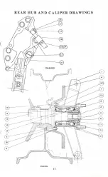
Page 12: ...REAR HUB AND CALIPER DRA WINGS 0 2 1 STANDARD 8 2 9 RACING 11 ...

Page 13: ...6 10 187 318 D 66871 2774X 2788A 2720 D 66872 67184 4 HU 077 2 16 W 28 Salisbury 4 HU 091 1 D 66053 64032764 5 D 6648I 376102W 3700634W 378711 64474288 378700 REAR HUB PART NUMBERS RACING 1 Rear Carrier 2 Hub Flange Bolt 3 Rear Hub 4 Rear Disc 5 Wheel Drive Pegs 6 Drive Peg Nuts 7 Oil Seal Outer Buttonwood 8 Oil Seal Inner Buttonwood 9 Spacer 10 Cone Outer Timkin II Cone Inner Timkin 12 Cup Tirnki...

Page 14: ...D 66872 and one small distance piece Fig 14 67184 the spacers will lift away without difficulty but the outer bearing Fig 10 Timkin 2774X then exposed will require a draw to facilitate removal 7 The distance spacer Fig 9 D 66871 will lift away without trouble when the bearing is removed 8 The bearing outer cups Fig 12 Timkin 2720 and oil seals Fig 7 Burtonwood 275 3346 10 and Fig 8 Burtonwood 187 ...

Page 15: ...ing Fig If Adjusting Nut D 66829 Fig 11 Sleeve D 66828 Fig 11 o Ring Superfect S H 96 307 Fig 11 Spherical Bearing Rose RBJ 210 Fig 11 Circlip Anderton NAM 1300 Fig II Wishbone Pin and Bearings Fig 6 photograph Nylon bushes 12DU 16 Fig 6 Rubber and metal seals 07S IOO SBW Fig 6 Clamp Bolts Ii i nut Fig 6 Chrome Pin D 668S1 Fig 6 Rear Suspension Trailing Link Fig 8 photograph 66877C Trailing Link t...

Page 16: ...railing link to lower wishbone bearing 8 Trailing link 9 Trailing link to chassis bearing 10 LOwerrear wishbone 11 Lower wishbone inner bearing 12 Differential front support reference to page 4 13 Upper wishbone inner bushes 14 Differential side hanger bearings refer to page 4 15 Shock absorber top mounting refer to page 36 Note Part numbers for suspension units above are itemised on page 14 Shock...

Page 17: ...do not require any further attention The inner wishbone bearing Fig II comprises a sealed metal ball joint RBJ 21O two circlips a steel tube threaded at the ends a in X 4 bolt with locking nut Attached to the threaded tube are two adjusting nuts the positioning of which determines the running angle of the rear wheeL The base of the rear upright is attached to the outer part of the wish bone by a c...

Page 18: ...ade to the front hub and caliper drawings page 18 TO REMOVE FRONT VERTICAL LINK 1 Unbolt caliper Fig 22 I6j3P and suspend by wire from chassis tube 2 Remove locking nut and wire from inside top wishbone Fig 1 page 23 and pull top of vertical link away Fig 2 C 66813 pages 18and 23 3 Remove with ring spanner the locking nut visible at the base of the vertical link and pull lower ball joint taper awa...

Page 19: ... FRONT HUB AND CALIPER DRAWINGS 27 14 i15 I 6 STANDARD 13 if lI 14 15 16 I RACING 18 ...

Page 20: ...iper 16j3P 64032770 1 23 h dia Soft locking wire 24 Gasket 378700 25 Banjo 64474288 26 Bolt 376102W 27 Flexible hose Girling Long 3700634W 28 Gasket 378711 29 Hub Dust Plug 67197 FRONT HUB PART NUMBERS RACING Shelby American C 66813 D 6682l C 66854 5 LM 11949 LM II910Timkin LM 67048 LM 67010Timkin D 66445 D 66446 FN 309 0 704 1 Wheel 2 Vertical Link 3 Stub Axle 4 Hub 5 Outer Bearing Cone Outer Bea...

Page 21: ... LM 11949 LM 1191O 6 The inner and outer roller Fig 5 and 6 cones will also come away with the hub 7 The spindle is then exposed complete with inner bearing cup Fig 6 and oil retaining disc Fig 7 D 66445 8 Should it be desired to remove the hub stub axle Fig 3 D 66821 from the front vertical link Fig 2 C 66813 remove the locking nut Fig 12 and plain washer at rear of upright the stub axle which is...

Page 22: ...oint The lower ball joint suspension unit is a sealed nylon impregnated hemisphere of similar pattern to the front suspension upper ball joint and does not require maintenance The method of construction and assembly is shown on the exploded photograph page 22 1 One 1 locking nut 2 Recessed washer This should be assembled with the recess facing downward 3 Rubber dust cover 4 Brass dust cover 5 Stee...

Page 23: ... 10 D 66810 Ball Cap Lock Washer II D 66808 Ball Socket Casing Socket Screw Cap Point PHOTOGRAPH LOWER BALL JOINT tV I CD 64 0 CD _I CD o I 0 o 0 9 0 t 0 I I t B S F Self lock Nut 2 D 66448 Special Washer 3 D 66368 Rubber Dust Shield 4 D 66803 Upper Dirt Shield Brass 5 D 66802 Dust Shield 6 D 6680l Upper Hemisphere 7 D 66366 Ball Pin 8 D 66370 Lower Hemisphere 9 D 66407 Belleville Washer 10 D 6632...

Page 24: ...D 67179 f B S F Self locking Nut Wishbone Pivot Cup D 66819 FRONT SUSPENSION WISHBONES The front upper and lower wishbones are attached to the chassis points by rubber bushes The recessed washers are inserted from the outside top wishbone with the mounting bolts inserted from inside the wishbone The recessed washers are inserted from inside the lower wishbone with the mounting bolt pushed through ...

Page 25: ... the two universal joints together on the splines provided at both ends of column it will then be possible to lift out the section complete To remove the top part of the column undo the pinch boIts at the base of the shaft 111 the driving compartment Undo the slide bolt under the dashboard the top column section may then be removed REMOVING STEERING RACK FROM CHASSIS Jack up the front of car and r...

Page 26: ...e at the top end of the column to raise or lower the steering undo the slide securing bolt behind the dash board together with the bolt located at the lower end of the column in the driving compartment the steering may then be adjusted to the desired position Re tighten bolts STEERING BALL JOINTS These are prepacked and sealed and require no attention during service 25 ...

Page 27: ... 1 i mm r 1l IJ c 1 1 0 1 __ I _ ___ I tv 0 RACK PINION ASSY R H II f0 13 I 17 ...

Page 28: ...10 18255 Thrust Spring 3 11 19007 Ball Housing 2 12 19004 Ball Seat 2 13 16057 Seal Clip Outer 2 14 19006 Tie Rod 2 15 18685 Rack Seal 2 16 15258 Seal Clip Inner 2 17 18255 Thurst Spring 3 18 13443 Damper Pad 1 19 19498 Plain Washer 1 20 19424 Grease Nipple Right hand Drive 1 15771 Grease Nipple Left hand Drive 1 21 19500 Pinion Right hand Drive 1 19499 Pinion Left hand Drive 22 19136 Support Yoke...

Page 29: ...g wear is automatic and no manual adjustment is required The present disc brake has friction segments which operate on a small area of the braking surface leaving a large proportion of the disc exposed to the atmosphere allowing maximum dissipation of heat Girling disc brakes fitted to the Cobra are self compensating and require no adjustment whatsoever The hand brake from chassis CSX2I88 is self ...

Page 30: ... TO remove and reverse the positioning of the pads on front and rear brakes at 2 000 miles intervals This procedure will not be necessarywith the parking brake Note Some Girling calipers are made in paired halves bolted to gether it should be emphasized that no useful purpose can be served by separating the two halves of the caliper It should also be noted that some calipers are manufactured with ...

Page 31: ...GIRLING FRONT BRAKE CALIPER TYPE 16 3P PART NUMBER 64032770 1 1 Front Brake Caliper 2 Brake Bleeder 3 Pad Retaining Shafts 4 Split Pin 5 Brake Pad 30 ...

Page 32: ...te with metal backing plates HAND BRAKE REPLACEMENT BRAKE PADS 1 Hold back spring tensioner and remove rubber dust cap from brake adjuster 2 Remove split pin on pull rod pivot pin 3 Tap out pivot pin 4 Pull apart clamping levers and push down brake pull rod to permit easy withdrawl of brake pads 5 The pads are both held by retaining springs which must be released before pads may be withdrawn 6 It ...

Page 33: ... Rear brake pad 7 Hand brake pads 2 Shaft retaining split pin 8 Split pin 3 Pad retaining shaft 9 Pull rod pivot pin 4 Automatic hand brake adjuster 10 Hand brake pull rod 5 Hand brake adjuster dust cop 11 Rear brake caliper 6 Hand brake pull rod 12 Brake bleeder 32 ...

Page 34: ...page 31 adjustment for clearance is automatically effected by applying the hand brake It may be necessary to slacken off the adjuster slightly to allow for the increased thickness with the new pads The handbrakc cable is preset before the car leayes the works and should not require further adjustment when new pads are fitted 33 ...

Page 35: ...ime jack up car and remove road wheel Remove the rubber cover from the bleeder nipple of the brake cylinder this will be found on the outside of the caliper Fit rubber bleeder tube in its place and allow to hang in a clean container or glass jar always keeping end of tube below surface of fluid Unscrew the nipple about three quarters of a turn with a suitable spanner and operate brake pedal up and...

Page 36: ...r is a self contained and trouble free unit and needs no servicing attention of any kind By means of a special seal in the damper the hydraulic fluid is kept in circulation in such a manner that leakage is not possible and therefore no topping up is required at any time The valving control built into these units is the result of extensive and exacting trials by Shelby America and A C Should the da...

Page 37: ... SPRING UNIT A Shock Abscrber C 66820Armstrong 4407Racing 4407 1Standard B Coil Spring C 66929Racing and Standard C Spring Spacer D 67124Racing and Standard D Spherical Bearing Rose RBJ 207 Racing and Standard E Circlip Anderton 2300 29Racing and Standard F Bolt t B S F 3 long Racing and Standard G Spacer D 66919Racing and Standard H Bolt i B S F 4 ins long Racing and Standard I Nut t B S F Self l...

Page 38: ...40 Hypoid oil is recommended for the steering rack and only if this is not available may another heavy duty gear oil be substituted WHEEL HUBS U K Shell Retinax Castrolease Mobilgrease Energrease L2 Ess High A Heavy MP Tmp Grease Overseas Shell Retinax Castro lease Mobilgrease Energrease L2 EssoBearing A Heavy MP Grease CHASSIS GREASE POINTS U K Shell Retinax Castro lease Mobilgrease Energrease L2...

Page 39: ... Twice yearly at seasonal change of oil or every 10 000miles After first 500 miles Check oil and top up if required Drain and refill oil OIL CAPACITY OF SALISBURY HYPOID AXLES Model Oil Capacity 6 HA Itpints 21 u s pints 1 0 litre HA 2 pints 2t U S pints 1 1 litres 3 HA 21 pints 2t U S pints 1 3 litres 4 HA 3 pints 31 U s pints 1 7 litres 2 HA 3 pints 3t U S pints 1 7 litres 5 HA 3 pints 3t U S pi...

Page 40: ...drive shafts Universal joints propeller shaft 3 000 miles Oil Distributor very sparingly in aperture provided in Distributor Housing using S A E 30 Oil Oil accelerator pedal shaft on bulkhead 4 000 miles Change Differential Oil Change Gearbox Oil Steering Pinion bearing grease very sparingly 5 000 miles Grease nipples parking brake cables Place S A E 30 oil sparingly on Carburettor linkages 10 000...

Page 41: ...connections for security and cleaning the spaces around the terminals at intervals as necessary CONTACT BREAKER During the first 500 miles 800 krn running of a new car the contact breaker heel tends to bed down it is therefore advisable to check the gap at this stage It is vitally important to keep the contact breaker points clean set to the correct gap and parallel to each other SMITHS ELECTRIC E...

Page 42: ...fferent from the rest it may be that acid has been spilled or has leaked from this particular cell or there may be a short circuit between the plates In this case the battery should be examined by a Service Depot or Agent EVERY 1 000 MILES OR MONTHLY BATTERY Remove the filler plugs from each of the cells of the battery and if necessary add sufficient distilled water to bring the electro lyte level...

Page 43: ...all to a steady charge which is most suitable for the particular state of charge of the battery It will be noticed from the ammeter readings that the dynamo does not charge at very low engine speeds This is because it is not rotating fast enough to generate sufficient energy to charge the battery The cut out which is an automatic switch connected between the dynamo and battery allows the flow of c...

Page 44: ...vided A defective relay must be replaced A discharged battery can be recharged by a long period of day driving or from an external source of current LOCK NuT AD JuSlING fIIU It is also possible that the performance of a horn may be upset by the fixing bolt working loose or b some component near the horn being loose If after carrying out the above examination the trouble is not rectified the horn m...

Page 45: ... the engine is provided for the purpose of preventing the battery being discharged by the current flowing through the coil windings when the engine is stopped A warning lamp is provided which gives a red light when the ignition is switched on and the car is running very slowly or is stationary thus reminding the driver to switch off Should the warning lamp burn out this will not in any way affect ...

Page 46: ...63 Model Number DeLuxe 6963 England and Europe SIDE AND TAIL LAMPS SIDE FLASHER LAMPS To gain access to the bulb turn the rim anti clockwise which will release the glass and rim from the lamp Note the bulb has offset securing pins and can only be inserted in the holder the correct way round thus ensuring the low wattage filament is used for the side lamp and high wat tage for the flasher American ...

Page 47: ...tes an overload protective device in the form of a thermostat which under conditions of excessive heating will disconnect the current supply to the motor When the motor windings have cooled and normal conditions restored the wiper will automatically re start A switch is situated in the centre of the instrument board To bring wipers into operation turn the switch to the right The wiper is so wired ...

Page 48: ...e ARMATURE e ts Z u z IH 1t j d BEARING HOUSI NG BRUSH GEAR ...

Page 49: ...CH 0 0 0 Gu GU G II GU WU I NW MAIN BEAM WA NING LIGHT LIGHTING Ii I SWITOI S 6 UW U 0 un UW R H HEAD LAMP MAIN BEAM UW Lw 1 B UW loH HEADLAMP DIP BEAM 1DIPPER SWITCH I UR UR iH EAD DIP BEAM _t 1 UR R H SIDELAMP I L H SIOELAMP 1 B L R R PANEL UGHT 1 f r I GV R H FRONT FLASH R GW I I Ui FRONT FLASHER I If 0 O_ GR GR LIGHT l R H TAIL LAMP I LH TAIL LAMP R I NUMBER PLATE LAMP R _0_ 0 I STOP L AMP ISO...

Page 50: ... spring clips in which it fits If it has blown the broken ends of the wire will be visible inside the glass tube Before replacing a blown fuse inspect the wiring of the units that have failed for evidence of a short circuit or other fault which may have caused the fuse to blow and remedy the cause of the trouble It is important to use only the correct replace _ V ment fuse The fusing value IS mark...

Page 51: ...s secured bya bayonet fixed backshell which also provides the contact to the bulb The design of the bulb and of its holder is such that the bulb is correctly positioned in relation to the reflector and no focusing is required when a replacement bulb is fitted Identical double filament bulbs are fitted in each lamp In the dipped position both headlamp beams are deflecteddownwardsand to the left rig...

Page 52: ...hat the thicker inner edge rests in the recess around the Light Unit rim Refit the front rim locating the top of the rim first and secure by means of the fixing screw HEADLAMP SETTING The lamps should be set so that the main driving beams are parallel with the road surface and with each other If adjustment is necessary remove the front rim and dust excluding rubber as described above and trim each...

Page 53: ...eari ng No 3 cer Expander Steel Crankpin Journal 2 1228 2 1236 Rails Chrome Pla Diameter ted Oxide Coated Expander Blued CAMSHAFT Steel Width No 1 0 0774 0 0781 Material Precision Molded No 2 0 0930 0 0940 Special Alloy Iron Gap e Nos 1 and 2 0 010 0 020 Bearings S Steel Back Babbitt No 3 0 0 IS 0 055 Inserts Camshaft Gear Cast Iron PISTON PINS Material Type Press Fit in Rod Material S A E SOlS Al...

Page 54: ...g Manual Centrifugal Advance r p m Degrees Housing Initial set test stand to 0 650 2t 3t Setting at 2500 r p m and 750 4 5t Maximum hot Idle 750 775 rvp m 0 HG 1000 6t 7t Adjustment 1600 7t 8t Fuel Pump Static 4 6 p s i 500 2000 8t 9t Pressure r p m Maximum Advance 14 BREAKER POINTS TORQUE LIMITS Arm Spring Ten 27 30 oz Intake Manifold 20 22 ft Ibs sion std ignition Exhaust Manifold 13 IS ft Ibs C...

Page 55: ...ng Jour able Inserts No 3 0 015 0 055 2 7484 2 7492 nal Diameter PISTON PINS Thrust Bearing No 3 Type Full Floating Crankpin Journal 2 4380 2 4388 Tubular Diameter Material S A E 5015 Alloy Steel Heat Treated CAMSHAFT Length 2 202 3 212 Material Precision Molded Diameter 0 9750 0 9753 Special Alloy Iron Bushing Bronze Bearings 5 Steel Back Babbitt CONNECTING RODS Inserts Material Forged Steel with...

Page 56: ...rmostatic Spring 58LI Identification BREAKER POINTS Choke Spring Hous At Index Mark Arm Spring Tension ing Initial Setting Fast cold Idle 1500 r p m std ignition 27 30 oz Adjustment trans ignition 22 24 oz Maximum hot Idle 700 800 r p m Contact Spacing 0 019 0 021 Adjustment Dwell Angle at Idle Fuel Pump Static 4t 6t p s i Speed std ignition 30 330 Pressure 500 r p m combined trans ignition 22 240...

Page 57: ... 9 Panel Lights 16 ScreenWasher 3 Speedometer 10 Wiper 17 Indicator Lever 4 Oil pressure Guage 11 Glove Box 18 Ignition Key 5 Water Temp Guage 12 Cigar Lighter 19 Revolution Counter 6 Oil Temp Guage 13 Heater two speed 20 Air Control 7 Ammeter 14 Headlamps 21 Ignition Light 56 ...

Page 58: ...top bars from rear boot 2 The two sections must be joined together and inserted in the sockets provided at rear of cockpit 3 Remove the soft top from the pocket provided at rear of seats holding the metal front section near the centre pins 57 ...

Page 59: ... centre Press the holding pins into the slot one at a time and pull sideways to engage the head of the pin under the channel 5 Push down studs at rear of the soft top with exception of the last three on either side 6 Push down holding clips at side of windscreen 58 ...

Page 60: ...ards to tension soft top and do up internal securing tabs 8 Push down remaining six studs on rear deck To remove the soft top reverse this procedure The thick perspex side screens are secured by inserting the bottom bars into door sockets 59 ...

Page 61: ...09 3HOU3 JOlId NIMOTIO 3HL l dOOV aor MOS NIO IO i N3HM ...

Page 62: ...rd bulbs 54 Dashboard instrumentation 55 E Electrical maintenance 34 Electric engine cooling fan 34 Electrical setting data 44 Electric wiring diagram 52 Electric horns 53 Erecting hood or soft top 56 F Folding soft top 59 Field coils 40 Front brake pads replacement 25 Front brake illustration 24 Foreword 1 Front hub removal 12 Front bearings removal 13 Front hub and caliper drawing B 14 Front hub...

Page 63: ...suspension 15 Rear suspension illustration 16 Rear suspension 17 Removal of front hub To remove front caliper To remove front vertical link 18 Front hub and caliper drawings 19 Front hub part numbers 20 To remove front wheel bearings Front suspension u pper ball joint 21 Front suspension lower ball joint 22 Front suspension ball joint photographs 23 Front upper and lower wishbones Front suspension...

Page 64: ...cas electric horns 44 Ignition warning light Dashboard bulbs 45 Headlamp bulb information Side and tail lamp bulbs 46 Lucas two speed wipers 47 Lucas wiper illustration 48 Electric wiring diagram 49 Fuse box 50 The starter Headlamps Europe and America 51 Headlamp removal and setting 52 289 Engine maintenance 53 289 Engine maintenance 54 427 Engine maintenance 55 427 Engine maintenance 56 Dashboard...

Reviews: