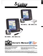
background image

Summary of Contents for Marine MC 600Ci

Page 1: ......

Page 2: ...r House Northumberland Avenue Dun Laoghaire Illinois 60707 USA County Dublin Ireland Cobra NightWatch Nothing Comes Close to a Cobra and the snake design are registered trademarks of Cobra Electronics Corpora tion USA Cobra Electronics CorporationTM CobraMarineTM and iASAPTM are trademarks of Cobra Electronics Corporation USA C MAPTM C MAP Navigation Technology C MAP NT MAX TM and C MAP NT TM are ...

Page 3: ...ler For additional information on C MAPTM Cartography visit web site at www c map com CUSTOMER ASSISTANCE INFORMATION Should you encounter any problems with this product or not understand its many features please refer to this Owner s Manual If you require further assistance after reading this Owner s Manual Cobra Electronics CorporationTM offers the following customer assistance services For Assi...

Page 4: ...odes of operation their labels for the current functions are shown on the screen right above the buttons They can also be used like FM radio preset buttons to save quick access to your favorite pages When pressing the ESC button the four software button labels disappear Owner s Manual Nothing Comes Close to a Cobra A2 ...

Page 5: ...ations Wrecks Obstructions Coordinates and User Points Display Tide Info and Tide Graph page Automatic Info on cartographic objects and User Points Display vessel s position direction and Track 10 Tracks with 16 Color Options Alarms Handling Anchor Drag Arrival Off Course Proximity Depth Etc Man OverBoard MOB to navigate back to a missing person or object Demo Modes TECHNICAL SECIFICATIONS Power C...

Page 6: ...only experienced technicians MUST handle The C MAPTM C CARDs are available from your local dealer Exposure of the display to UV rays may shorten the life of the liquid crystals used in your plotter This limitation is due to the current technology of the LCD displays Avoid overheating which may cause loss of contrast and in extreme cases a darkening of the screen Problems which occur from overheati...

Page 7: ...ce Guide External GPS Antenna with 10 Meter Cable ONLY on MC 600Cx model Flush Mount Kit ONLY on MC 600Cx with model MC 600C Chart Details The chartplotter has a built in world map that can be used for Route planning To use the chartplotter as a navigation aid charts are required with detailed information for the area This chart cartridge is called a C CARD C CARDs are available from your local C ...

Page 8: ...t Procedure 8 2 BASIC OPERATION 10 2 1 SWITCHING ON OFF 10 2 1 1 Switching On 10 2 1 2 Switching Off 10 2 1 3 Auto power On Description 10 2 2 INITIAL SETUP 10 2 2 1 Definitions of Selections 11 2 3 ADJUSTING THE BACKLIGHTING AND CONTRAST 12 2 4 PAGE SURFING 13 2 4 1 Pages selection 13 2 5 DEMO MODE 14 2 5 1 Full Demo 14 2 5 2 Demo a Route 14 2 5 3 Custom Demo 14 2 6 MOVING AND ZOOMING ON CHART 14...

Page 9: ...le Layouts of HIGHWAY Page 31 3 5 2 2 ZOOM IN AND ZOOM OUT 31 3 5 3 Menu 31 3 6 SUN AND MOON PAGE 32 3 6 1 Description Telling Tide 32 3 6 2 Operations 32 3 6 2 1 Available Layouts of SUN and MOON Page 33 3 6 2 2 Finding the Nearest Tide Stations 33 3 6 2 3 Finding a Tide Station on a map 33 3 6 2 4 Changing the date for the Tide Chart 34 3 6 2 5 Various Animation Options 34 3 7 FISH FINDER PAGE 3...

Page 10: ...a Waypoint 50 4 3 ROUTE OPERATIONS 50 4 3 1 Selecting existing and Naming new Routes 51 4 3 2 Basic Route List Operations 51 4 4 USING TRACK 52 4 5 USER POINTS LIST 53 4 5 1 Selecting Existing and naming new User Points 53 4 5 2 Basic User Point List Operations 53 4 6 USER C CARD OPERATIONS 54 4 6 1 User C CARD Page 54 4 6 2 Formatting User C CARD 54 4 6 3 Saving file on User C CARD 55 4 6 4 Loadi...

Page 11: ...4 5 2 11 About 75 6 INSTALLATION 76 6 1 BASIC 76 6 1 1 Chartplotter Dimensions 76 6 1 2 C CARD Inserting and Removing 76 6 1 3 Chartplotter Installation and Removing 77 6 1 4 Wiring and Connectors 77 6 2 ADVANCED 78 6 2 1 External NMEA Connection 78 6 2 2 GPS Connection on MC 600Cx with External GPS 78 6 2 3 Autopilot and Basic DSC VHF Connection 78 6 2 4 External Alarm Connection 79 6 2 5 Fish Fi...

Page 12: ...0Ci chartplotter models Whenever it is necessary a note has been inserted for the model with differences 1 2 2 Menu Description Many of the options listed under the Page Information and Operation Instructions should be read from start to finish Duplicate items are not mentioned for each Page Operation Example Menu Item descriptions will not be listed for each page if they have already been describ...

Page 13: ...box appears with the available selections 2 4 6 HIDE 3 Use the UP and DOWN CURSOR buttons to select a desired choice 4 Press the ENTER button to confirm or the ESC button to abort and return to the previous settings Pressing the RIGHT CURSOR button will sometimes perform like the ENTER button during this operation 1 2 4 Alphanumeric Input Procedure Information is keyed into the chartplotter for ex...

Page 14: ...desired character is highlighted 3 Press the ENTER button to confirm the selected character appears in the highlighted field on the top line 4 Repeat this procedure until you complete your entry 5 Press the SAVE software button when the entry is complete This keypad is designed to reduce the number of button presses needed naming points and entering data It can be disabled and the more conventiona...

Page 15: ...for first time switch On instructions 2 1 2 Switching Off Press and hold the PWR button for three 3 seconds A countdown timer appears on the screen if you release the button before the countdown timer reaches zero the chartplotter will remain On 2 1 3 Auto power On Description If you power Off the chartplotter during the normal working using an accessory switch not pushing the PWR button then the ...

Page 16: ...al Logo Screen BOAT MODEL optional Enters the Model Name Number of your boat to be displayed on the Logo Screen BOAT NAME optional Enters the boat name to be displayed on the Logo Screen COMPASS BEARINGS Selects either degrees magnetic or degrees true If magnetic readings are selected the variation is computed automatically for every zone as soon as the chart is displayed DISTANCE UNITS Sets the d...

Page 17: ...he default setting is Knots Nautical Miles Hour Other options are M S BFT Miles per Hour Mph and Kilometers per Hour Kph APPROXIMATE MAX SPEED This information will be used to set up the analog style speedometer gauge CURRENT ENGINE HOURS optional Starting value that will be used for the engine hours gauge WAYPOINT ARRIVAL ALARM Sets the distance you would like to have alarm sound when approaching...

Page 18: ...selection Pressing the PAGE button causes TABs to appear with the pages that you can scroll through Continually pressing the PAGE button or the RIGHT and LEFT CURSOR buttons allow you to scroll forwards or backwards through the available pages The TABs disappear after several seconds allowing you to resume full operation of the selected page Please note that these available pages can be customized...

Page 19: ...is mode is designed for in store or on display demonstration This unit will automatically scroll through various displays and demonstrate the product 2 5 2 Demo a Route This mode allows the user to select a Route that they have already planned 2 5 3 Custom Demo This mode allows you to enter a desired course and speed for the demonstration The simulated GPS position will start directly from the Poi...

Page 20: ... ESC button is used to come back to original map Pointer location and a map scale after zooming and panning 2 7 CHANGING DATA FIELDS ON MOST PAGES It is possible to change the number of data fields shown at the bottom of most Pages The number of fields and the value displayed in the field can be changed by selecting the MAIN Menu and then either the NUMBER OF DATA FIELDS or CHANGE DATA FIELDS opti...

Page 21: ...e appears around one of the data fields 4 Use the UP DOWN RIGHT and LEFT CURSOR buttons to highlight and choose an individual data field 5 Press the ENTER button to display the available data options for the chosen data field 6 Use the UP and DOWN CURSOR buttons move through the options 7 Press the ENTER button to select the on screen option or the ESC button to cancel and return to the previously...

Page 22: ...2 8 CREATING A USER POINT A User Point is an object that you can place on the charts to mark a specific point The chartplotter features two types of User Points Marks and Waypoints 2 8 1 Creating a New Waypoint A Waypoint is created when entering a Route 1 Move the Pointer to the desired location on the chart 2 Press the ENTER button 3 Use the UP or DOWN CURSOR button to select NEW WAYPOINT and pr...

Page 23: ...er off the location to accept You can also use the shortcut software buttons that appear when moving the Pointer See the following picture 2 9 CREATING A BASIC ROUTE To create a Route 1 Move the Pointer to the desired location on the chart 2 Press the ENTER button 3 Use the UP or DOWN CURSOR button to select NEW WAYPOINT and press the ENTER button This places the first Waypoint of the new Route on...

Page 24: ... Route list but with the next open Route highlighted Software button choices are EDIT ACCEPT NEW WAYPOINT A new Waypoint is created and set as the destination Waypoint NEW MARK A new Mark is created MOB Man OverBoard MOB function See Par 2 12 for details FIND Find function See Par 2 11 for details 2 11 USING FIND The Find function allows searching for the nearest Ports Port Services Tide Stations ...

Page 25: ...lable 2 12 1 Inserting MOB To activate a MOB function follow the procedure below 1 Press the MOB button A dialog box with a message MOB is activated will appear on a screen and a MOB Waypoint will be created 2 If the NMEA output is turned On the warning dialog box is given Turn off autopilot before setting MOB point as destination 2 12 2 Deleting MOB To cancel the MOB function 1 Use the CURSOR but...

Page 26: ... Off 4 Press one of the bottom software buttons to assign it as a short cut to the desired page The RIGHT and LEFT CURSOR buttons can also be used to change the selection if the page has already been assigned a button During future operations the ON pages can be selected using the PAGE button which is generally used to scroll through all available pages Pages containing certain data like the Fish ...

Page 27: ...to return to the WELCOME Page 8 different options are available from this page MY BOAT ON CHART Goes back to the CHART Page centered on the vessel s position CLOSEST FUEL Goes right to the list of closest Fuel Stations with distance and bearing listed PICK A POINT Goes to the predefined User Point list with the closest point highlighted GAUGES AND DATA Goes to the DATA Page FIND MARINE SERVICES Sh...

Page 28: ...WATCHTM MODE Selection toggles between Day and NightwatchTM depending on what mode the display is in at the time of selection The screen will be difficult to read if the chartplotter is in NightwatchTM mode and the sun is to bright With the chartplotter on continuously pressing the PWR button will get the chartplotter out of NightwatchTM mode Welcome Page ...

Page 29: ...as described later in this paragraph The central section of the screen provides visual guidance of a chart and the bottom of the page is designed for navigation data display 3 3 2 Operations The CHART Page is used for display of electronic cartography creating and using the User Points plotting position and navigational data 3 3 2 1 Available Layouts of CHART Page The data fields of the CHART Page...

Page 30: ...uttons are activated when moving the Pointer with the CURSOR buttons They acts as a shortcuts for the GOTO functions including GO TO POINTER NEW ROUTE NEW WAYPOINT and NEW MARK These functions time out after several seconds The ESC button disables these software buttons for several more seconds 3 3 3 Menu The MAIN Menu selected through the MENU button of the CHART Page provides the operations for ...

Page 31: ... the Tidal arrows on the selected area at any given time See also Par 4 8 MEASURE Allows measuring Distance and Bearing between two points on the CHART Page See also Par 4 1 FIND The same as pushing the Find button See Par 2 11 TRACKS Allows the management of the Track See also Par 4 4 ROUTES Allows the management of the Route See also Par 4 3 USER POINTS LIST Selects the User Points List Page wit...

Page 32: ...alues can be configured by pressing the RIGHT or LEFT CURSOR button located on the right side panel The default page is the 3 Boxes page with the Analogue Style Speedometer Gauge 3 4 2 2 Changing Data Options The content of each data field can be adjusted to user s requirements To customize data options follow the procedure described in Par 2 7 2 Changing Data Fields The default Speed Gauge data f...

Page 33: ...e such as Reset Trip Log Reset Total Log Reset Maximum Speed Screen Instructions and Data Field tools Press the ENTER button to accept any selected menu option or the ESC button to cancel your choice RESET TRIP LOG Resets the distance traveled since it was last reset RESET TOTAL LOG Clears the total traveled distance RESET MAX SPEED Resets the highest boat speed measured since the Speed Log was sw...

Page 34: ...e are ON by default This option allows the users to turn OFF these Screen Instructions once they are familiar with the features DEFAULT DISPLAY Changes the DATA Page that is the first displayed Default page layout is set to 3 fields with the Analogue GPS Speed shown Data Page ...

Page 35: ...he bottom of the page is designed for navigation data display The line down the center of the highway represents the desired track line The distance between a vessel and a Target can be changed using the ZOOM IN and ZOOM OUT buttons The distance from the center line to the side of the highway is indicated on the display As a vessel heads towards its destination the highway perspective moves to ind...

Page 36: ...r view of a highway ZOOM OUT Press ZOOM OUT button to change the scale and show a wider less detailed view The distance from the center line to either side of the highway will change from 0 2 0 5 1 0 2 0 4 0 10 0 ZOOM IN Press the ZOOM IN to show a narrower more detailed view 3 5 3 Menu The MAIN Menu of the HIGHWAY Page provides the same operations as the CHART Page display but it also provides so...

Page 37: ...ata fields set by default and a graph showing Tide information from a given Tide station The highest Tides are represented by the top of the curve and the lowest Tides by the bottom of the curve Tide heights are indicated at height of Tide above the mean low Tide LATITUDE LONGITUDE Location of the Tide symbol station on the chart DATE TIME Date and Time of the indicated data HIGH WATER LOW WATER T...

Page 38: ...earing will appear Highlight your selection with the CURSOR buttons and press the ENTER button The result of your selection will be visible on a graph If there is no available Tide Station in the nearest area the message appears If necessary use the Pointer to select a location closer to a Tide Station and use the FIND feature to find the closest station 3 6 2 3 Finding a Tide Station on a map Usi...

Page 39: ...mation Options Using the MAIN Menu it is possible to activate two additional options able to animate the Tide info using some future predictions concerning time and date PLAY TIME FORWARD Runs the vertical line along the X Axis horizontally at a rate of 0 75 Hours Second A vertical line travels up and down on the Y axis following the intersection of the curve When the day comes to an end then the ...

Page 40: ...nar image of the water column beneath the Fish Finder sensor The most recent items passing under the transducer are displayed on the right side of the screen The scale which is visible on the right side of the screen indicates the depth of the area which is being currently displayed from the top to the bottom of the screen The top left corner is dedicated for the depth information Temperature of t...

Page 41: ...is triggered when depth is outside the range Depth ruler Vertical graduated bar It is a scale which reflects the depth of the area being displayed Variable Depth Marker VDM Horizontal line on to the Echogram window with a depth label The up down cursor buttons can move it up and down The label displays the depth of the cursor position It can be moved to any location pinpointing the depth of a targ...

Page 42: ...NU button enables to set the actual sonar data fish symbols or a combination of both After changing the Frequency of a sonar signal the graphical presentation of items may change slightly Thermoclines Are the zones where two layers of different water temperatures meet The greater the temperature differential the thicker the thermocline is shown on the screen Thermoclines are represented as horizon...

Page 43: ... delivered by the optional external Fish Finder device Access to most of the options for the FISH FINDER Page are available via the MAIN Menu 3 7 2 1 Available Layouts of FISH FINDER Page The data fields of the FISH FINDER Page can be customized to HIDE 2 4 or 6 through the MENU button By default the FISH FINDER Page is specified for 2 data fields 3 7 2 2 Changing Data Options The content of each ...

Page 44: ... mode DUAL FREQUENCY SCREEN Divides the screen to show the 50 Khz images on one side and the 200 Khz images on the other side GAIN MODE Controls the sensitivity of the unit s receiver which provides some flexibility in the display To see more details increase the receiver sensitivity by selecting a higher gain percentage To decrease the rate of details select a lower gain percentage RANGE MODE Sel...

Page 45: ...tion of underwater suspended targets Several options are available including the option to show the depth of each Target RESET DEFAULTS Resets the default Fish Finder setting and tuning adjustments Zoom In and Zoom Out will zoom in on the bottom or on a selected depth if you use the CURSOR UP or CURSOR DOWN button to select a depth The CURSOR UP or CURSOR DOWN button allows you to set depth upper ...

Page 46: ...ge the yellow box from the Chart window to the Fish window 3 8 2 Operations 3 8 2 1 Moving the location of the Chart Window It is possible to set the CHART Page view in 4 different locations Left Right Up or Down To customize the COMBO MODE Page follow the procedure 1 Press the MENU button to activate the MAIN Menu 2 Use the UP and DOWN CURSOR buttons to select CHART LOCATION option 3 Press the EN...

Page 47: ...vate this option follow the procedure below 1 Press the MENU button to activate the MAIN Menu 2 Use the UP and DOWN CURSOR buttons to highlight ADJUST SPLIT and press the ENTER button 3 A yellow line is shown indicating the ability to drag the boundary of each separate page Also the arrow icons indicating the available directions to move the line will be visible 4 In case of vertical combo screens...

Page 48: ...low the procedure below 1 Select the SCREEN CONTROL option from the MAIN Menu 2 Use the CURSOR buttons to activate a desired window The active window will be highlighted in yellow 3 Press the ENTER buttons to confirm your selection After page activation both the functions of hardware buttons and Menu options correspond to their functions on a given page Pressing the MENU button brings up the appro...

Page 49: ...uidance to the destination The default setting is Chart on a bottom and Highway on top 50 200 This mode combines both frequencies 50 and 200kHz to get the best coverage area and depths readings By default the 50 kHz window displayed on the left and the 200 kHz window on the right SPLIT ZOOM It is possible to set the display to show a split screen view One side will show a zoom portion of the sonar...

Page 50: ...functions of hardware buttons and Menu options correspond to their functions on a given page Pressing the MENU button brings up the appropriate menu for the area which is highlighted and enables all relevant page functions Press and hold the PAGE button for more than one 1 second to change the Screen Control 3 9 2 Menu Pressing the MENU button on the SPLIT MODE Page activates all the commands spec...

Page 51: ...n view The progress of satellite acquisition is shown in three stages No signal strength bars the receiver is looking for the satellites indicated Red signal strength bars the receiver has found the satellite s and is collecting data Green signal strength bars the receiver has collected the necessary data and the satellite s are ready for use The GPS Page is ready for navigation when device has co...

Page 52: ...ializes and restarts the GPS GPS SETUP Goes to the GPS Settings in the SYSTEM Page COM SETTINGS Goes to the COM Settings in the SYSTEM Page The GPS Page is turned OFF by default It will be visible until a position is acquired when the chartplotter is first powered up It must be turned ON in the PAGES ON OFF selection from the SYSTEM Page see the Par 3 1 to view after that GPS Page ...

Page 53: ...ins many settings that can be customized by the user but are usually not necessary The Fish Finder settings are grayed when unavailable To select a desired option use the CURSOR buttons and the ENTER button to confirm your selection Every sub menu acts in the same way Press the ESC button to abort given action 3 11 2 Each Setting Description For detailed description of all individual data fields a...

Page 54: ... precise navigation or to quickly gauge the distance from one location to another Move the Pointer to any location to start the MEASURE function from that location 4 2 ADVANCED WAYPOINT OPERATIONS Now that you have had a chance to became familiar with your new chartplotter there are a great number of advanced features that you will find helpful You may delete Waypoint from a Route insert a Waypoin...

Page 55: ... desired Route leg 2 Press the INSERT software button 3 Use the CURSOR buttons to move the Pointer to the new position and press the ENTER button the new Waypoint is placed 4 2 4 Editing a Waypoint You can modify name symbol color and position of any Waypoint in the Route 1 Use the CURSOR buttons to place the Pointer on existing Waypoint which you want to edit 2 Press the EDIT software button 3 Us...

Page 56: ...sic Route List Operations After the table activation on a display the software buttons appear on a bottom of a screen with the following options Select the desired row and use these software buttons DETAILS Shows the Route info you may change the name DELETE Deletes the Route Route legs and Waypoints are deleted If the destination is placed on the Route that Route cannot be deleted LOCATE Displays...

Page 57: ... DOWN CURSOR button to select the desired row The following operations are available This feature is sometimes known as trail or breadcrumb trail ACTIVE TRACK Selects the number of the active Track The default setting is 1 TRACKING Turns ON or OFF the Track storing It is not possible to use the Track storing if you are not receiving a valid fix The default setting is On VISIBLE Turns ON or OFF the...

Page 58: ...ter can store a fix after a defined time Choose among 1 5 10 30 sec 1 5 10 min The default setting is 1 sec 4 5 USER POINTS LIST To give information and allow the editing of all stored User Points Use the procedure below to select and operate the User Point List page 4 5 1 Selecting Existing and naming new User Points 1 Press the MENU button from one of the CHART Pages select USER POINTS LIST and ...

Page 59: ...llows to back up Marks Routes and Tracks to a User C CARD This allows virtually unlimited storage This C CARD is available through C MAPTM dealers Please visit www c map com for a list of dealers 4 6 1 User C CARD Page To display the content of a User C CARD inserted into the C CARD slot of your chartplotter To select this item follow the procedure 1 Press the MENU button from the CHART Page The M...

Page 60: ... leaving you with little flexibility The secret is to find a compromise a point where you can combine a date with a word creating a unique filename The maximum length of the filename is 8 characters The characters may be numbers 0 9 letters A Z and spaces for example legal identifiers are ABC AA 12121212 A B C 1 A 1 and so on 4 6 4 Loading file from User C CARD The Load function copies the content...

Page 61: ...ic Info will be shown most of the times the Pointer is moved 4 7 2 Selecting Automatic Info 1 Use the CURSOR buttons to move the Pointer on the object The pop up window with the basic info of the objects is displayed To get full details of the object press the EXPAND software button 4 7 3 Info on objects with Pictures On the Quick Info there is the camera icon on the top bar of the window if at le...

Page 62: ...s you to change any Tidal current arrows on the display to predict future conditions To select the Currents Prediction item follow the procedure 1 Press the MENU button from one of the CHART Pages select CURRENT PREDICTIONS and press the ENTER button 2 A window is shown on the left side of the chart It is possible to see the variation of the Tidal arrows on the selected area at any given time Plac...

Page 63: ...the image associated can represent the Diagram representing the shape of the objects and the various characteristics length height type of bridge etc Place your Pointer over the camera icon to show a picture 4 11 DSC CALLING DSC Digital Selective Calling is a method of establishing a VHF radio call DSC had also been designated as part of the Global Maritime Distress and Safety System GMDSS It is p...

Page 64: ...to receive any DSC distress call within a range When a call is received an alert message appears at the VHF DSC CALLING Page All the received calls are sorted by date and time It is possible to select the whole line with the UP and DOWN CURSOR buttons After selection the on screen labeled software buttons are activated LOCATE DELETE POSITION REQUEST and DETAILs 4 11 2 Contact List After pressing t...

Page 65: ...hance the visibility of the screen depending on the surrounding light condition The possible choices are SUNLIGHT NORMAL CLASSIC NOAA and NIGHT SUNLIGHT is designed to enhance the visibility of the screen when the chartplotter is exposed to the sunlight The maps are much brighter than in the other modes and the depth areas are filled with white color so different depth areas are not easily disting...

Page 66: ...raphs 5 2 2 1 Chart Presentation Controls the display on the map of the chart features After the CHART SETTINGS menu is shown 1 Use the UP or DOWN CURSOR button to select CHART PRESENTATION and press the ENTER button 2 Use the UP or DOWN CURSOR button to select the desired option and then press the ENTER button The available options are listed below CHART PRESETS Selects from a predefined table wh...

Page 67: ...ble to show the name number of the buoys next to the icon on the chart CHART POINT NAMES Turns ON or OFF the displaying of the Names local area names NAV AID PRESENTATION Sets the Nav Aid presentation as US or INTernational When selected it affects Lights Signals Buoys Beacons display INTernational Draws Nav Aids using international symbology US Draw Nav Aids using NOAA symbology All components of...

Page 68: ...and then merged to the electronic charts in order to provide more information useful for the navigation VAD object can be any cartographic objects and it can be distinguished from the official chart objects from the Quick Info A dedicated icon is shown on the Quick Info window to indicate that the object queried is a VAD The same icon is also shown on the Full Info page and in addition the extende...

Page 69: ...press the ENTER button The available options are listed below ZOOM TYPE Allows larger expansion or compression of the chart scale while zooming in or out Zoom Type has two options STANDARD default or FLEXI ZOOM When in FLEXI ZOOM mode a short ZOOM button push causes a change of chart whilst a long ZOOM button push press and hold causes a pop up window to be displayed on a corner of the screen The ...

Page 70: ... not used it may be disabled USER POINTS Selections are VISIBLE ICON and HIDDEN Visible shows both file name and icon on the chart AUTO INFO Allows displaying information on cartographic object when the Pointer is placed on it The Automatic Info On Points shows information when the Pointer is placed on points as Port Services Tides lights wrecks rocks buoys beacons obstructions land markers etc Th...

Page 71: ...ation of the reference angle after which the map changes its orientation SAFETY STATUS BAR Displays a status bar with 6 fields showing the status of certain functions Any warning or alarm condition is identified by the red colour to indicate possible risk NAV AIDS Turns ON or OFF the graphical presentation of Lights Signals Buoys and Beacons LIGHT SECTORS Turns ON or OFF the display of Light Secto...

Page 72: ... affect the map information COMPASS BEARINGS Selects either degrees magnetic or degrees true If magnetic readings are selected the variation is computed automatically for every zone as soon as the chart is displayed COMPASS VARIATION Calculates the Magnetic Variation in an Automatic or manual mode by inserting the step for calculation of Magnetic Variation QUADRANT CALIBRATION Allows you enter qua...

Page 73: ...oft FISH SYMBOLS Determines the graphical representation of underwater suspended targets It is possible to choose ECHO ECHO ICON ECHO ICON DEPTH ECHO DEPTH ICON ICON DEPTH The Fish icons displayed are displayed using four different shapes depending on the size of the Target Small Med Big Huge 5 2 4 2 Sensitivity Settings The SENSITIVITY SETTINGS menu allows you to select the Fish Finder setup info...

Page 74: ... bottom in the whole depth range 0 4000 Feet even if the range displayed is lower If Range Mode is Manual the Fish Finder will search the bottom only within the range manually set by the user In the Range Mode the bottom search is slower because always search the whole range In the Manual Mode the bottom search is quicker and is particularly useful when due to extreme working conditions the Fish F...

Page 75: ... measuring device insert here a positive negative offset to display right value on Fish Finder screens CALIBRATE AUX TEMP Calibrates of the Aux Temperature sensor Using the readings from a precise temperature measuring device insert here a positive negative offset to display right value on FF screens 5 2 5 Alarm Settings The chartplotter provides alarms for various functions You can enter the desi...

Page 76: ...eport of the dangerous objects currently detected When any of the searched objects is found in the scanned area a tick marker is printed on the relative box to identify which dangerous objects have been currently detected Once the alarm condition is no longer present the relative tick marker is removed 5 2 5 3 Fish Alarms SHALLOW ALARM Triggers an alarm when depth becomes shallower than the value ...

Page 77: ...information 5 2 8 GPS Settings When the GPS device is connected properly the GPS Settings menu provides the access to GPS functions and features connected with the satellites information used for further navigation All the options are described below INTERNAL GPS Turns ON or OFF the Internal GPS RESTART GPS If GPS is connected restarts all GPS processes Once executed the message OK is shown Press ...

Page 78: ...l correction of fix position The correction is entered as X Y offset in minutes and thousand of minutes 9 999 5 2 9 Demo The built in Demo function allows you to become proficient in the use of the chartplotter It simulates the reception of the navigation data Lat Lon Course Speed date time The simulated ship s position is placed at the current Pointer position by the time the simulation is activa...

Page 79: ...SENTENCES Allows customizing the NMEA 0183 sentence transmitted on each port Each port can transmit a different set of sentences among GLL VTG BOD XTE BWC RMA RMB RMC APB WCV GGA HSC HDG APA DBT DPT MTW VHW PORT 2 INPUT Sets the format for the navigation data input serial Port2 For example to set the Port as NMEA 0183 4800 Baud Rate Parity None 8 Bits Number 1 Stop Bit and Normal Polarity you must...

Page 80: ...Nothing Comes Close to a Cobra 75 5 2 11 About To see details about the software and cartography data installed open the System Information page About ...

Page 81: ... the chartplotter 6 1 1 Chartplotter Dimensions 6 1 2 C CARD Inserting and Removing A notch for removing the cover is available on the bottom Hold the C CARD by the long inclined side so that you can see the C MAPTM label Gently push the C CARD into the slot push the C CARD in as far as it will and place the front cover again Chartplotter Dimensions C CARD Inserting ...

Page 82: ...ired location is found attach the mounting base to the area using the supplied hardware Flush Mounting The chartplotter external antenna model only is supplied with a flush mount template for the cutout hole and screw holes required to install the chartplotter Before installing ensure there are no obstructions behind the location that could interfere with the mounting and there is physically enoug...

Page 83: ...that are used to connect the chartplotter to Power Supply to the GPS WAAS Smart antenna optional FISH FINDER and to NMEA devices 6 2 1 External NMEA Connection 6 2 2 GPS Connection on MC 600Cx with External GPS 6 2 3 Autopilot and Basic DSC VHF Connection Advanced ...

Page 84: ... in the immediate proximity to the antenna The antenna relies on direct line of sight satellite reception If you are unsure of the chosen location temporarily mount the antenna in the desired location to verify correct operation If mounted close to Radar and after the chartplotter has received a fix turn On the Radar to ensure the chartplotter holds the fix see the GPS Page Par 3 10 The thread use...

Page 85: ...e below 1 Remove the threaded base from the antenna dome 2 To ease installation a flush mounting template for the antenna has been included 3 Apply the mounting template sticker to the area that was verified for the GPS reception 4 Drill out the 0 63 16mm and 0 16 4mm holes and remove the template 5 Insert the cable into the 0 63 16mm hole and route to the chartplotter 6 Apply a small amount of se...

Page 86: ...vice and are still having problems with your chartplotter the extended auto test should help determine the problem Make sure the chartplotter is turned Off While pressing and holding any other button turn the chartplotter On A new menu will appear on the display Use the CURSOR button to select the desired test this will display in reverse video To choose the test press the ENTER button To exit fro...

Page 87: ...he transducer which contains an element that converts the pulse into acoustic sound wave which is sent through the water As this wave travels from the transducer to the bottom it may strike fish structures thermoclines temperature changes in the water When the wave strikes an object s a certain amount of the wave is reflected back to the transducer depending on the composition and shape of the obj...

Page 88: ...ears to blow relative to a moving point also called Relative Wind Direction AWS Apparent Wind Speed The Speed at which the Wind appears to blow relative to a moving point also called Relative Wind Speed Beacon A prominent specially constructed object forming a conspicuous vertical mark as a fixed aid to navigation Bearings Selects either degrees magnetic or degrees true If magnetic readings are se...

Page 89: ...sels Icon Course Line course is given by the value of COG Course Over Ground and its length is proportional to the SOG Speed Over Ground CTS Course To Steer The optimum direction the boat should be steered in order to efficiently make headway back to the courseline while also proceeding toward the destination Waypoint Cultural Features Any man made topographic feature as built up area buildings ro...

Page 90: ...d time of reaching a destination or Waypoint File Collection of information of the same type stored on a User C CARD Each file must have a unique name ideally one that describes its contents Filenames are kept in a directory on each User C CARD Fix Current position of the vessel provided by the GPS connected to the chartplotter or built in or other positioning systems Fix Status Indicates the qual...

Page 91: ...rovided by an instrument with a submerged transducer for measuring the distance speed traveled by the vessel Longitude Angular distance East or West of the prime meridian Greenwich meridian as measured by lines perpendicular to the parallels and converging at the poles from 0 to 180 Loran Positioning system which determines the current position of the vessel by measuring the difference in the time...

Page 92: ...in Pictures Diagrams The MAX data format allows assigning one or more image to any cartographic object These Pictures are typically used to facilitate the identification of cartographic objects or places around the map they can be the landscape layout nearby a harbor the shape of a bridge or of a buoy etc On some objects such as bridges the image associated can represent the Diagram representing t...

Page 93: ...d chain Between any two stations a ship must be located somewhere along a line of possible positions where the measured Time Difference TD between arrival of pulses from those stations would be observed The TD is measured from the time of reception of the master station signal to the time of reception of the slave station signal see also Pair Tide Periodic rise and fall of the surface of oceans ba...

Page 94: ...gle between the magnetic and geographic meridians at any place expressed in degrees West or East to indicate the direction of magnetic North from true North It changes from point to point and at the same point with time WAAS Wide Area Augmentation System The Federal Aviation Administration FAA in cooperation with other DOT organizations and DOD is augmenting the GPS SPS with a satellite based augm...

Page 95: ...U S Department of Defense was conceived for military purposes but now it is used in a host of civilian applications GPS navigation uses satellite signals to determine your position in relation to a set of satellites orbiting the earth The GPS constellation of satellites continuously send radio signals containing the precise position for each satellite back to earth By knowing the position of 3 or ...

Page 96: ...accuracy is mainly due to this technology 3 When the satellite locations and their distances are known the GPS receiver fixes its own position by triangulation As illustrated in the previous figure the position is calculated as the meeting point of three spheres which are drawn around the three satellites with diameters d1 d2 and d3 9 2 2 Position Fixing Accuracy HDOP The GPS fix accuracy is due t...

Page 97: ...92 Owner s Manual GPS The index for position fixing accuracy is called HDOP Horizontal Dilution Of Precision The smaller the HDOP value the more accurately the position can be fixed ...

Page 98: ...0 to W 052 50 4 Caracas W 052 50 to W 037 50 3 Rio de Janeiro W 037 50 to W 022 50 2 Fernando de Noronha W 022 50 to W 007 50 1 Azores Islands W 007 50 to E 007 50 GMT 0 London E 007 50 to E 022 50 1 Rome E 022 50 to E 037 50 2 Cairo E 037 50 to E 052 50 3 Moscow E 052 50 to E 067 50 4 Abu Dhabi E 067 50 to E 082 50 5 Maldives E 082 50 to E 097 50 6 Dhuburi E 097 50 to E 112 50 7 Bangkok E 112 50 ...

Page 99: ...GINE HOURS 12 CURRENT PREDICTIONS 26 57 CURSOR CONTROL 73 Custom Demo 14 73 D Data Fields 15 16 Data Options 17 DATA Page 27 DATE 73 DATE FORMAT 12 72 DATE TIME 32 Datum 84 DAY OR NIGHT MODE 23 Dead Reckoning 84 Default 84 DEFAULT DISPLAY 29 DELETE 52 Deleting file 55 Deleting MOB 20 Deleting Waypoint 49 51 Demo 73 DEMO MODE 14 23 DEPTH 11 69 72 DEPTH ALARM 71 Depth Area 85 Depth Line 85 DEPTH MOD...

Page 100: ...E MODE 39 69 removing C CARD 76 RESET DEFAULTS 12 40 RESET DEPTH LIMITS 39 RESET MAXIMUM SPEED 28 RESET TOTAL LOG 28 RESET TRIP LOG 28 RESTART GPS 47 72 ROADS 64 ROCKS MAX 63 ROCKS MIN 63 Route 26 50 55 87 RTCM 88 S SAFETY STATUS BAR 66 Saving file 55 SCREEN AMPLIFIER 66 SCREEN INSTRUCTIONS 29 SCROLLING SPEED 39 68 SEABED TYPES 67 Selecting an option 7 SEND REC ROUTES MARKS 74 SENSITIVITY 39 Sensi...

Page 101: ......

Page 102: ......

Reviews: