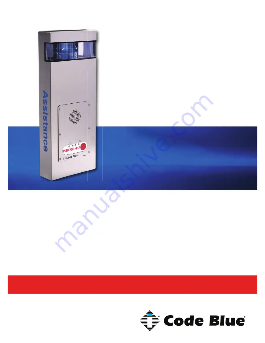
background image

800.205.7186 

 www.codeblue.com

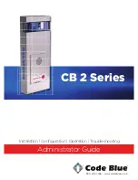
Administrator Guide

CB 2 Series

Installation | Confi guration | Operation | Troubleshooting

Summary of Contents for CB 2-a

Page 1: ...800 205 7186 www codeblue com Administrator Guide CB 2 Series Installation Configuration Operation Troubleshooting...

Page 2: ...TO THIS GUIDE THE SOFTWARE OR OTHER INFORMATION CONTAINED HEREIN AND HEREBY EXPRESSLY DIS CLAIMS ANY IMPLIED WARRANTIES OF MERCHANTABILITY OR FITNESS FOR ANY PARTICU LAR PURPOSE WITH REGARD TO THIS G...

Page 3: ...ED Light Connectors 21 15 CB 2 a Installation Instructions 23 16 CB 2 e Installation Instructions 26 17 Legacy CB 2 e Installation Instructions 29 18 Legacy CB 2 e with Public Address Installation Ins...

Page 4: ...iring prior to 2020 53 33 CB 2 Series Standard Wiring prior to 3 2013 with Hammond Transformer 54 34 Legacy Cb 2 e with Public Address Wiring Diagram 55 35 Legacy CB 2 e with AED Housing Wiring Diagra...

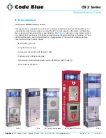
Page 5: ...disasters All 2 Series units have a rugged steel construc tion shatterproof Lexan Lens industrial engineering grade reflective graphics and weather UV and graffiti resistant paint and are illuminated...

Page 6: ...2 Each analog speakerphone requires its own phone line or PBX extension Multiple units shall not be supported 3 Speakerphones require programming before operation Consult the User Guide or Administra...

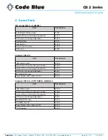
Page 7: ...ws 41500 HID Lens 41164 Legacy CB 2 e Part Part Number LED Strobe Light 40159 Button Head Security Screws 3 pack 41500 Analog Phone Line Surge Suppressor 41471 IP Phone Line Surge Suppressor 41421 Man...

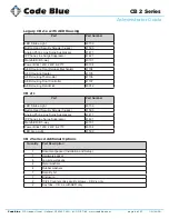
Page 8: ...ng Heater 41105 AED Housing Thermostat 41106 AED Housing Door Controller 41107 AED Housing Retrofit kit 40012 CB 2 s Part Part Number LED Strobe Light 40159 Button Head Security Screws 3 pack 41500 An...

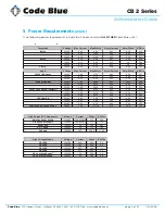
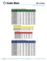
Page 9: ...DC 1 05 12 60 0 30 24V DC 1 05 25 20 0 60 CB 5 s 5 p 24V AC 0 48 11 52 0 28 12V DC 0 67 8 04 0 19 24V DC 0 67 16 08 0 39 CB 9 s 24V AC 0 26 6 24 0 15 12V DC 0 43 5 16 0 12 24V DC 0 43 10 32 0 25 CB 2...

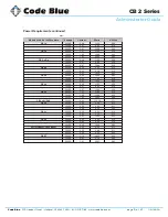
Page 10: ...C 1 31 31 44 0 75 12V DC 1 05 12 60 0 30 24V DC 1 05 25 20 0 60 CB 5 s 5 p 24V AC 0 48 11 52 0 28 12V DC 0 67 8 04 0 19 24V DC 0 67 16 08 0 39 CB 9 s 24V AC 0 26 6 24 0 15 12V DC 0 43 5 16 0 12 24V DC...

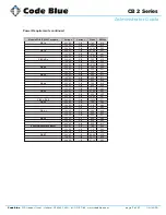
Page 11: ...32 0 25 CB 9 s 24V AC 0 11 2 64 0 06 12V DC 0 19 2 28 0 05 24V DC 0 19 4 56 0 11 CB 2 e 24V AC 0 29 6 96 0 17 12V DC 0 39 4 68 0 11 24V DC 0 39 9 36 0 22 CB 2 a 24V AC 0 33 7 92 0 19 12V DC 0 43 5 16...

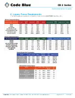
Page 12: ...t Holland MI 49423 USA 800 205 7186 www codeblue com GU 149 AA page 12 of 63 CB 2 Series Administrator Guide 6 Legacy Power Requirements The following power requirements include the 2 Series and also...

Page 13: ...Code Blue 259 Hedcor Street Holland MI 49423 USA 800 205 7186 www codeblue com GU 149 AA page 13 of 63 CB 2 Series Administrator Guide...

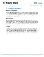
Page 14: ...ts effectively by re motely controlling emergency communication devices with an easy to use Graphical User Interface GUI You also will have the ability to open gates and AED access doors turn LED beac...

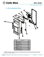
Page 15: ...in component identification Reference the model and serial number from the unit ID tag and contact manufacturer to confirm replacement part version and availability 4 6 2 7 8 1 5 3 12 10 11 9 ITEM DES...

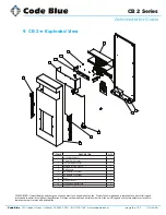
Page 16: ...ded to assist in component identification Reference the model and serial number from the unit ID tag and contact manufacturer to confirm replacement part version and availability 5 3 2 6 7 1 4 11 9 10...

Page 17: ...ALL Standard Custom Graphic 7 50001 Single Button IA4100 Analog Phone PUSH FOR HELP 7 50002 Double Button IA4100 Analog Phone PUSH FOR HELP 7 50003 Keypad IA4100 Analog Phone PUSH FOR HELP 7 50004 Sin...

Page 18: ...aphic 6 CALL Custom Graphic 7 50001 Single Button IA4100 Analog Phone PUSH FOR HELP 7 50002 Double Button IA4100 Analog Phone PUSH FOR HELP 7 50003 Keypad IA4100 Analog Phone PUSH FOR HELP 7 50004 Sin...

Page 19: ...alog Phone PUSH FOR HELP 2 50002 Double Button IA4100 Analog Phone PUSH FOR HELP 2 50003 Keypad IA4100 Analog Phone PUSH FOR HELP 2 50004 Single Button IA4100 Analog Phone EMERGENCY 2 50005 Double But...

Page 20: ...hone PUSH FOR HELP 2 50002 Double Button IA4100 Analog Phone PUSH FOR HELP 2 50003 Keypad IA4100 Analog Phone PUSH FOR HELP 2 50004 Single Button IA4100 Analog Phone EMERGENCY 2 50005 Double Button IA...

Page 21: ...e area and faceplate lights come with Wago connectors These con nectors provide ease of use and a much stronger connection Below are the steps needed to change to the new connectors Each new LED light...

Page 22: ...tight Place small screwdriver into square hole and push down Insert cut wire into round hole and remove screwdriver Repeat on the rest of the connectors Once all connectors have been switched you are...

Page 23: ...quipment generates uses and can radiate radio frequency energy and if not installed and used in accordance with the instruc tion manual may cause harmful interference to radio communica tions Operatio...

Page 24: ...our mounting holes 6 Drill all marked holes with appropriate drill bit 7 If attaching to concrete or brick insert one 3 8 anchor into each drilled hole 8 If attaching to wood 3 8 lag bolt is required...

Page 25: ...ue 259 Hedcor Street Holland MI 49423 USA 800 205 7186 www codeblue com GU 149 AA page 25 of 63 CB 2 Series Administrator Guide Mounting Schematics 1 25 1 80 9 80 2 21 28 21 1 30 10 30 1 30 10 30 26 0...

Page 26: ...quipment generates uses and can radiate radio frequency energy and if not installed and used in accordance with the instruc tion manual may cause harmful interference to radio communica tions Operatio...

Page 27: ...ark the four mounting holes 26 Drill all marked holes with appropriate drill bit 27 If attaching to concrete or brick insert one 3 8 anchor into each drilled hole 28 If attaching to wood 3 8 lag bolt...

Page 28: ...ue 259 Hedcor Street Holland MI 49423 USA 800 205 7186 www codeblue com GU 149 AA page 28 of 63 CB 2 Series Administrator Guide Mounting Schematics 1 25 1 80 9 80 2 21 28 21 1 30 10 30 1 30 10 30 26 0...

Page 29: ...nsure that the conduit is aligned at this time 2 5 Reattach the top 3 0 WIRING 3 1 Ground The ground green wire should be stripped and fastened to the supplied ground ing lug 3 2 24V AC supply The uni...

Page 30: ...Code Blue 259 Hedcor Street Holland MI 49423 USA 800 205 7186 www codeblue com GU 149 AA page 30 of 63 CB 2 Series Administrator Guide...

Page 31: ...plates For dual button faceplate deduct 3 25 inches For keypad faceplate deduct 4 5 inches For wheelchair direct facing access only deduct 6 inches DISCLAIMER The dimensions above are intended as gui...

Page 32: ...The ground green wire should be stripped and fastened to the supplied grounding lug 3 2 24V AC supply The unit will contain a 5 finger manifold with corresponding fuses per component Incoming power i...

Page 33: ...Code Blue 259 Hedcor Street Holland MI 49423 USA 800 205 7186 www codeblue com GU 149 AA page 33 of 63 CB 2 Series Administrator Guide...

Page 34: ...plates For dual button faceplate deduct 3 25 inches For keypad faceplate deduct 4 5 inches For wheelchair direct facing access only deduct 6 inches DISCLAIMER The dimensions above are intended as gui...

Page 35: ...ould be positioned between 34 and 48 inches from grade level Consult an ADA specialist in your area to verify local and federal guide lines 2 3 Drill all marked holes 2 4 Install the housing Four anch...

Page 36: ...Code Blue 259 Hedcor Street Holland MI 49423 USA 800 205 7186 www codeblue com GU 149 AA page 36 of 63 CB 2 Series Administrator Guide 11 23 06 15 5 12 53 9 00 3 00 36 00 21 00 8 00 46 72...

Page 37: ...r direct facing access only deduct 6 inches DISCLAIMER The dimensions above are intended as guidelines only For specific installation requirements reference your local codes All wiring must be install...

Page 38: ...the Americans with Disabilities Act ADA of 1990 the speakerphone button s should be positioned between 34 and 48 inches from grade level Consult an ADA specialist in your area to verify local and fede...

Page 39: ...Code Blue 259 Hedcor Street Holland MI 49423 USA 800 205 7186 www codeblue com GU 149 AA page 39 of 63 CB 2 Series Administrator Guide...

Page 40: ...duct 6 inches DISCLAIMER The dimensions above are intended as guidelines only For specific installation requirements reference your local codes 30 3 4 30 3 4 43 43 2 9 16 2 9 16 6 6 1 1 2 1 1 2 12 REF...

Page 41: ...g tool sold separately on the Parts Order Form part 41441 1 0 THREAD MOUNTING STRAPS THROUGH SLOTS 1 1 Use outside slots for larger poles and inside slots for smaller poles 2 0 HOLD BRACKET TO POLE 2...

Page 42: ...s recommend that the device be checked once per week for proper op eration Some units will give an audible chirp if the self diagnostics have failed and the unit needs service others may use another i...

Page 43: ...K fasten the strobe J to the round portion of the strobe bracket NOTE If the beacon strobe is mounted upside down a drain hole must be drilled into the lens to prevent it from filling with water 3 0...

Page 44: ...URE S 1050 MODEL The Steadyburn Mode will be ON in dark or night ambient environments and OFF in bright or daylight ambient environments The S 1050 LED Beacon Strobe has two built in photo response fe...

Page 45: ...r disconnected for 20 seconds BEFORE reapplying When power is reapplied the unit will operate as programmed above NOTE If you do not leave power disconnected for 20 seconds before reapplying power the...

Page 46: ...Line For High Voltage leave connected For Low Voltage disconnect and apply incoming power Incoming Low Voltage 25 CB 2 a Standard Wiring 2020 Product wiring diagram shown reasonably represents curren...

Page 47: ...r Incoming POE To Ground 26 CB 2 a PoE Wiring 2020 Product wiring diagram shown reasonably represents current offering and is intended to assist in component identification and service Earlier product...

Page 48: ...TLOOK EHKAOED2 CB2A WIRING DIAGRAM B VSD SIZE FSCM NO DWG NO REV DRAWN Mike Rose CB 2a Wiring Diagram B ISSUED 7 22 16 SCALE 1 1 7 26 2016 SHEET 3 OF 3 Revised date in out GRD Front Panel Disconnect H...

Page 49: ...Line For High Voltage leave connected For Low Voltage disconnect and apply incoming power Incoming Low Voltage 28 CB 2 e Standard Wiring 2020 Product wiring diagram shown reasonably represents curren...

Page 50: ...r Incoming POE To Ground 29 CB 2 e PoE Wiring 2020 Product wiring diagram shown reasonably represents current offering and is intended to assist in component identification and service Earlier product...

Page 51: ...lts AC or DC IA4100 LAN LAN LAN PoE PAS Control PAS Audio Audio Output 1 Optional Battery 12V 2 0Ahr Ethernet Aux Output 2 Aux Input 1 Aux Output 1 Aux ports IP5000 12 24 Volts AC or DC Beacon Strobe...

Page 52: ...with the PoE switch port power will be granted to the Splitter and the indicator along with the device attached will turn on CAT5e 3ft in out GRD 3ft Cat5e Customer Cat5e A 700 Electcial Modes 12VDC...

Page 53: ...Brick Wiring prior to 2020 Product wiring diagram shown reasonably represents current offering and is intended to assist in component identification and service Earlier product production may have dif...

Page 54: ...ammond Transformer with Hammond Transformer Product wiring diagram shown reasonably represents current offering and is intended to assist in component identification and service Earlier product produc...

Page 55: ...OUTPUT 1 2 3 N O N C G 3 1 2 4 BATT ACC POWER AUX INPUTS 12 24V AC or DC standard BATT PWR Aux Out put 1 Battery 12V 2 0Ahr Aux Out put 2 Aux Input 1 Battery 12V 2 0Ahr POWER MANIFOLD MULTI TAP RJ 11...

Page 56: ...s intended to assist in component identification and service Earlier product produc tion may have different components and wiring connections Reference the model and serial number from the unit ID tag...

Page 57: ...N O N C G 3 1 2 4 BATT ACC POWER AUX INPUTS 12 24V AC or DC standard BATT PWR Aux Out put 1 Battery 12V 2 0Ahr Aux Out put 2 Aux Input 1 Battery 12V 2 0Ahr POWER MANIFOLD MULTI TAP RJ 11 cord Fiber t...

Page 58: ...C 24 VA 2V DC Converter 12VDC 12VDC 12VDC 2a mp fuse 24VAC 2a mp fuse Multi Ta ransformer Primary Incoming Supplier Primary Side of the Transformer Secondar Transformer White Yellow Brown Gray Black 2...

Page 59: ...nections are tight and clean Verify no stains exist around gasket areas Stains indicate leaking and gasket should be replaced Verify moisture weep hole on cabinet bottom is open and unobstructed Verif...

Page 60: ...e adhered to The Surface Care Frequency table below provides general guidelines to assist in configuring a schedule Please note that the frequency of care required to guard the Code Blue unit s surfac...

Page 61: ...6 www codeblue com GU 149 AA page 61 of 63 CB 2 Series Administrator Guide 39 Locating Unit Serial Numbers Remove the speakerphone faceplate with the special security bit The serial number will be lis...

Page 62: ...port for this product while under warranty is available at www codeblue com support In Case of Breakdown In case of system breakdown discontinue use and contact Tech Support at ts codeblue com or call...

Page 63: ...esources guides 8 Phone Enclosures Administrator Guide www codeblue com resources guides 9 Stainless Steel Maintenance Guide www codeblue com support 10 IA4100 Administrator Guide www codeblue com res...

Reviews: