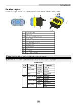
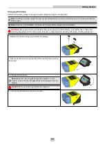
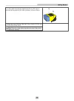
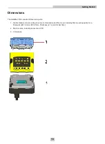
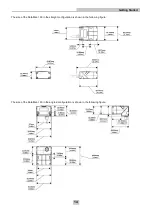
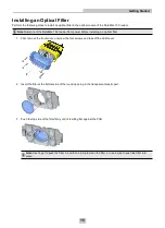
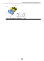
Cognex DataMan 150, Quick Reference Manual
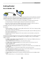
The Cognex DataMan 150 is a cutting-edge barcode reader designed for seamless data capture. Get up to speed in an instant with our Quick Reference Manual, a comprehensive user manual that you can download for free from 88.208.23.73:8080. Accessible and user-friendly, maximizing the potential of your device has never been easier.
Share
Download

Reviews:
No comments
Related manuals for DataMan 150

BS-i201G
Brand: TVS electronics Pages: 2

MH941
Brand: Metrologic Pages: 33

1426915
Brand: Conrad Pages: 12

ANT-RDR
Brand: AMX Pages: 2

ARE i2-LF
Brand: AEG Pages: 39

ARE H9
Brand: AEG Pages: 36
ARE i2 - HF
Brand: AEG Pages: 50
ARE I2
Brand: AEG Pages: 33

ViVOpay VP5200
Brand: IDTECH Pages: 15

Z-8082 Lite
Brand: Zebex Pages: 22

On The Go!
Brand: Budgie Pages: 73

AYC-F60 Series
Brand: Rosslare Pages: 66

MR9610
Brand: Accuris Pages: 38

DS4600A
Brand: Datalogic Pages: 63

BT-49
Brand: Flash Pages: 190

iLS6303XBU
Brand: RIOTEC Pages: 4

FS5020E
Brand: RIOTEC Pages: 33

iDC9500K
Brand: RIOTEC Pages: 6


