background image

In-Sight

®

9902L

Vision System

Reference Guide

2018 July 19
Revision: 5.6.1.39

Summary of Contents for In-Sight 9902L

Page 1: ...In Sight 9902L Vision System Reference Guide 2018July19 Revision 5 6 1 39 ...

Page 2: ...eans electronic or mechanical for any purpose nor transferred to any other media or language without the written permission of Cognex Corporation Copyright 2018 Cognex Corporation All Rights Reserved Portions of the hardware and software provided by Cognex may be covered by one or more U S and foreign patents as well as pending U S and foreign patents listed on the Cognex web site at http www cogn...

Page 3: ...pt any interference received including interference that may cause undesired operation This equipment generates uses and can radiate radio frequency energy and if not installed and used in accordance with the instruction manual may cause harmful interference to radio communications Operation of this equipment in a residential area is likely to cause harmful interference in which case the user will...

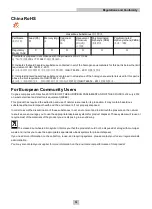
Page 4: ... of 4 July 2012 on waste electrical and electronic equipment WEEE This product has required the extraction and use of natural resources for its production It may contain hazardous substances that could impact health and the environment if not properly disposed In order to avoid the dissemination of those substances in our environment and to diminish the pressure on the natural resources we encoura...

Page 5: ...dity impact vibration corrosive substances flammable substances or static electricity l Do not expose the image sensor to laser light image sensors can be damaged by direct or reflected laser light If your application requires the use of laser light that may strike the image sensor a lens filter at the corresponding laser s wavelength is recommended Contact your local integrator or application eng...

Page 6: ...he Breakout Cable 15 Replace the SD Card Optional 16 Specifications 17 Vision System Specifications 17 Acquisition Trigger Input 19 Encoder Inputs 20 Encoder Input Wiring 20 General Purpose Input 21 High Speed Outputs 22 High Speed Output Wiring 23 Ethernet Cable 24 Breakout Cable 25 Dimensions 26 Vision System Dimensions 26 Vision System with Cover COV 7000 CMNT LG 27 Vision System with Cover COV...

Page 7: ... of a hazard that could result in death serious personal injury or electrical shock CAUTION This symbol indicates the presence of a hazard that could result in property damage Note Notes provide supplemental information about a subject Tip Tips provide helpful suggestions and shortcuts that may not otherwise be apparent 7 Symbols ...

Page 8: ...Help and EasyBuilder Help files provided with In Sight Explorer software l On demand training http www cognex com on demand training aspx l The In Sight online support site http www cognex com Support InSight Standard Components Note l Cables are sold separately l If any of the standard components appear to be missing or damaged immediately contact your Cognex Authorized Service Provider ASP or Co...

Page 9: ... the working distance l Refer to C Mount Lens Clearance Dimensions on page 29 for more information Large C Mount cover and adapter COV 7000 CMNT LG Note If using the COV 7000 CMNT LG cover the maximum lens length is 77mm with a bandpass filter the maximum lens body diameter is 55mm and the maximum diameter including locking screws is 55mm C Mount cover extender COV 7000 CMNT LGX Cables Breakout ca...

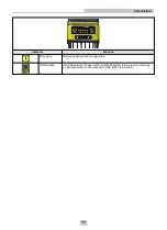
Page 10: ...mage focus score 0 10 while in Live Video Mode within In Sight Explorer TRIG Button Manually triggers an image acquisition when the vision system is either l Online within In Sight Explorer and the acquisition Trigger parameter is set to Manual l Offline within In Sight Explorer Power LED The green LED illuminates to indicate that the vision system is powered on SD Card Status LED l Off The SD car...

Page 11: ...nction Error LED Red when active User configurable TUNE Button Used as an Event Trigger within In Sight Explorer to force a cell containing an Event structure to run when the TUNE button is pressed 11 Introduction ...

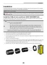
Page 12: ... lens threads and body protrude more than 6 5mm you can add a spacer between the lens and vision system However the spacer decreases the working distance l If using the COV 7000 CMNT LG cover the maximum lens length is 77mm with a bandpass filter the maximum lens body diameter is 55mm and the maximum diameter including locking screws is 55mm 1 Remove the rubber faceplate covering the image sensor ...

Page 13: ... it should be attached to one of the four mounting points on the back plate of the vision system and not to the mounting points on the front of the vision system 1 Align the holes on the mounting surface with the mounting holes on the vision system 2 Insert the M4 screws into the mounting holes and tighten using a 2 5mm hex wrench the maximum torque is 0 90 Nm 8 in lb Note The maximum insertion de...

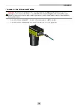
Page 14: ...ded Ethernet connector A digital voltmeter should be used to validate the grounding If the far end device is not grounded a ground wire should be added in compliance with local electrical codes 1 Connect the Ethernet cable s M12 connector to the vision system s ENET connector 2 Connect the Ethernet cable s RJ 45 connector to a switch router or PC as applicable 14 Installation ...

Page 15: ... that the 24VDC power supply being used is unplugged and not receiving power 2 Optionally connect the I O wires to an appropriate device for example a PLC encoder or serial device For more information refer to Breakout Cable on page 25 3 Attach the Breakout cable s 24VDC Red wire and GND Black wire to the corresponding terminals on the power supply CAUTION Never connect voltages other than 24VDC A...

Page 16: ...bles are properly attached or the provided connector plug installed the IP67 rated lens cover is properly installed and the Micro SD card cover is fastened in place l Observe ESD precautions when installing or removing an SD card or other accessories 1 Remove power from the vision system 2 Unscrew the screws in the Micro SD card cover and open the card slot 3 Remove the existing SD card from the M...

Page 17: ...nputs 1 general purpose input when connected to the Breakout cable Discrete Outputs 2 high speed outputs when connected to the Breakout cable Encoder Inputs 2 built in encoder inputs for use with a 24VDC signal Status LEDs SD Card Status Pass Fail LED and Indicator Ring Network LED and Error LED Network Communication 1 Ethernet port 10 100 1000 BaseT with auto MDIX IEEE 802 3 TCP IP Protocol Suppo...

Page 18: ...each X Y Z axis 80 Gs 800m s 2 at 11ms half sinusoidal with cables or cable plugs and a 150 gram or lighter lens attached Vibration Shipping and Storage 2 IEC 60068 2 6 vibration test in each of the three main axis for 2 hours 10 Gs 10 to 500 Hz at 100m s 2 15mm with cables or cable plugs and a 150 gram or lighter lens attached Regulations Conformity CE FCC KCC TÜV SÜD NRTL EU RoHS China RoHS 1 To...

Page 19: ... the start of acquisition The line period varies depending on acquisition settings Input pulse should be a minimum of 1ms wide l To trigger from an NPN type photoelectric sensor or PLC output connect COMMON IN to 24VDC and connect TRIGGER to the output of the photoelectric sensor When the output turns ON it pulls TRIGGER down to 0VDC turning the opto coupler ON For more information refer to Breako...

Page 20: ... Voltage ON 5 to 24VDC OFF 2VDC Current ON 1000µA OFF 0µA Resistance 350 kOhms Maximum Encoder Frequency 96KHz assuming a 50 50 duty cycle Encoder Input Wiring For single encoders the ENCODER A pin must be used For quadrature encoders the ENCODER A or ENCODER B pin can be used For more information refer to Breakout Cable on page 25 20 Specifications ...

Page 21: ... input OFF 830µA for 5VDC input Resistance 6 Kohms Delay 1 11ms maximum latency between leading edge of trigger and start of acquisition Input pulse should be minimum of 1ms wide l For NPN lines connect COMMON IN to 24VDC and connect IN 1 to the output of the photoelectric sensor or PLC When the output turns ON it pulls IN 1 down to 0VDC turning the opto coupler ON l For PNP lines connect IN 1 to ...

Page 22: ...otection diode Delay1 25μs maximum due to opto isolators turning ON For NPN lines the external load should be connected between the output and the positive supply voltage 26 4VDC The output pulls down to less than 3VDC when ON which causes current to flow through the load When the output is OFF no current flows through the load For PNP lines the external load should be connected between the output...

Page 23: ... directly to the PLC input When enabled the output pulls the PLC input up to greater than 21VDC To connect the high speed outputs to a relay LED or similar load connect the negative side of the load to the output and the positive side to 24VDC When the output switches on the negative side of the load is pulled down to less than 3VDC and 24VDC appears across the load Use a protection diode for a la...

Page 24: ...The Ethernet cable shield must be grounded at the far end Whatever this cable is plugged into typically a switch or router should have a grounded Ethernet connector A digital voltmeter should be used to validate the grounding If the far end device is not grounded a ground wire should be added in compliance with local electrical codes Note l Cables are sold separately l The wiring for this cable fo...

Page 25: ...d 8 GND Black 9 COMMON OUT Green 10 TRIGGER Orange 11 HS OUT 0 Blue 12 HS OUT 1 Grey Note l Cables are sold separately l Exposed wires can be cut short or wire ends trimmed and the wires tied back using a tie made of non conductive material Keep all bare wires separated from the 24VDC wire l Perform wiring or adjustments to I O devices when the vision system is not receiving power 25 Specification...

Page 26: ...the vision system and optional accessories Vision System Dimensions Note l All dimensions are in millimeters inches and are for reference purposes only l All specifications are for reference purpose only and may be changed without notice 26 Specifications ...

Page 27: ...with Cover COV 7000 CMNT LG Note l All dimensions are in millimeters inches and are for reference purposes only l All specifications are for reference purpose only and may be changed without notice 27 Specifications ...

Page 28: ...7000 CMNT LG and Extender COV 7000 CMNT LGX Note l All dimensions are in millimeters inches and are for reference purposes only l All specifications are for reference purpose only and may be changed without notice 28 Specifications ...

Page 29: ...en screwed in unless the diameter of the back lens is smaller than 19 25mm If the C Mount lens threads and body protrude more than 6 5mm you can add a spacer between the lens and vision system However the spacer decreases the working distance l All dimensions are in millimeters inches and are for reference purposes only l All specifications are for reference purpose only and may be changed without...

Page 30: ...The air must be free of oil moisture or other contaminants that could remain on the glass and possibly degrade the image Do not touch the glass window If oil smudges still remain clean the window with a cotton bud using alcohol ethyl methyl or isopropyl Do not pour the alcohol directly on the window Clean the Cover To remove dust from the lens cover use a pressurized air duster The air must be fre...

Page 31: ......

Reviews: