Johnson Controls Unitary Products
129099-UUM-G-0909
USER’S INFORMATION,
MAINTENANCE AND
SERVICE MANUAL
HIGH EFFICIENCY SEALED COMBUSTION
GAS FURNACE
MODELS: DGAA and DGAH
(Single Stage Downflow Only)
EFFICIENCY
RATING
CERTIFIED
ISO 9001
Certified Quality
Management System
For Installation In:
1.
Manufactured (Mobile) Homes
2.
Recreational Vehicles & Park Models
3.
Modular Homes & Buildings
TABLE OF CONTENTS
CONTACT INFORMATION FOR USA . . . . . . . . . . . . . . . . . . . . . . . 1
CONTACT INFORMATION FOR CANADA . . . . . . . . . . . . . . . . . . . 1
SAFETY . . . . . . . . . . . . . . . . . . . . . . . . . . . . . . . . . . . . . . . . . . . . . . . . 1
While you are away . . . . . . . . . . . . . . . . . . . . . . . . . . . . . . . . . . . . 2
SEASONAL SERVICE INFORMATION . . . . . . . . . . . . . . . . . . . . . . 2
Your Service Technician . . . . . . . . . . . . . . . . . . . . . . . . . . . . . . . . 2
DESCRIPTION . . . . . . . . . . . . . . . . . . . . . . . . . . . . . . . . . . . . . . . . . 2
WARRANTY AND RESPONSIBILITIES . . . . . . . . . . . . . . . . . . . . . 2
GAS SUPPLY . . . . . . . . . . . . . . . . . . . . . . . . . . . . . . . . . . . . . . . . . . 3
Natural Gas Operation . . . . . . . . . . . . . . . . . . . . . . . . . . . . . . . . . . 3
Propane Gas Operation . . . . . . . . . . . . . . . . . . . . . . . . . . . . . . . . . 3
INSTRUCTIONS FOR EXAMINING
THE FURNACE INSTALLATION . . . . . . . . . . . . . . . . . . . . . . . . . . . 3
Observing Burner Operation . . . . . . . . . . . . . . . . . . . . . . . . . . . . . 3
If Furnace Fails to Operate Properly . . . . . . . . . . . . . . . . . . . . . . . 4
HOW YOUR GAS FURNACE WORKS . . . . . . . . . . . . . . . . . . . . . . 4
IF FURNACE FAILS TO OPERATE PROPERLY . . . . . . . . . . . . . . 4
When You Call For Service Assistance . . . . . . . . . . . . . . . . . . . . . 4
To Contact Your Serviceman (fill in) . . . . . . . . . . . . . . . . . . . . . . . 4
START-UP AND SHUTDOWN INSTRUCTIONS . . . . . . . . . . . . . . . 4
Read the Instructions Below Before Trying
to Start the Furnace . . . . . . . . . . . . . . . . . . . . . . . . . . . . . . . . . . . . 4
Operating Instructions: . . . . . . . . . . . . . . . . . . . . . . . . . . . . . . . . . . 4
To Turn Off the Appliance: . . . . . . . . . . . . . . . . . . . . . . . . . . . . . . .5
FURNACE USER MAINTENANCE . . . . . . . . . . . . . . . . . . . . . . . . .5
Air Filters . . . . . . . . . . . . . . . . . . . . . . . . . . . . . . . . . . . . . . . . . . . .5
Removing Filters . . . . . . . . . . . . . . . . . . . . . . . . . . . . . . . . . . . . . .5
Blower Care . . . . . . . . . . . . . . . . . . . . . . . . . . . . . . . . . . . . . . . . . .6
Motor Lubrication . . . . . . . . . . . . . . . . . . . . . . . . . . . . . . . . . . . . . .6
SERVICE AND MAINTENANCE MANUAL . . . . . . . . . . . . . . . . . . . . .6
SAFETY SECTION . . . . . . . . . . . . . . . . . . . . . . . . . . . . . . . . . . . . . .6
FURNACE MAINTENANCE SECTION . . . . . . . . . . . . . . . . . . . . . .6
FURNACE CLEANING SECTION . . . . . . . . . . . . . . . . . . . . . . . . . .6
Burner Removal/Cleaning . . . . . . . . . . . . . . . . . . . . . . . . . . . . . . .6
Cleaning the Heat Exchanger . . . . . . . . . . . . . . . . . . . . . . . . . . . .6
THE FURNACE CONTROLS AND THEIR FUNCTION . . . . . . . . . .6
SEQUENCE OF OPERATION . . . . . . . . . . . . . . . . . . . . . . . . . . . . .7
Continuous Blower . . . . . . . . . . . . . . . . . . . . . . . . . . . . . . . . . . . . .7
Heating Cycle . . . . . . . . . . . . . . . . . . . . . . . . . . . . . . . . . . . . . . . . .7
Hot Surface Ignition System . . . . . . . . . . . . . . . . . . . . . . . . . . . . . .7
TROUBLESHOOTING . . . . . . . . . . . . . . . . . . . . . . . . . . . . . . . . . . .7
FURNACE CONTROL DIAGNOSTICS . . . . . . . . . . . . . . . . . . . . . .8
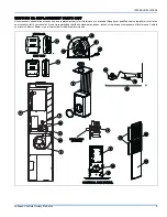
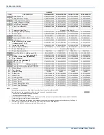
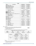
REPLACEMENT PARTS LIST . . . . . . . . . . . . . . . . . . . . . . . . . . . . . .9
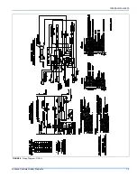
WIRING DIAGRAM . . . . . . . . . . . . . . . . . . . . . . . . . . . . . . . . . . . . . .12
LIMITED WARRANTY . . . . . . . . . . . . . . . . . . . . . . . . . . . . . . . . . . . .14
CONTACT INFORMATION FOR USA
•
Contact us by mail:
CONTACT INFORMATION FOR CANADA
•
Go to website at www.york.com click on “contact”, then click on
“contact form” and follow the instructions.
•
Contact us by mail:
York International
Consumer Relations
5005 York Drive
Norman, OK 73069
The manufacturer recommends that the user read all
sections of this manual and keep the manual for
future reference.
SECTION I: SAFETY
1.
The furnace area must be kept clear and free of combustible mate-
rials, gasoline and other flammable vapors and liquids.
2.
Insulating materials may be combustible. The furnace must be
kept free and clear of insulating materials. The furnace area must
be examined when installed in an insulated space or when insula-
tion is added to be sure that the insulation material has been kept
away from the furnace.
3.
Follow the instructions exactly as shown on the OPERATING
INSTRUCTION LABEL or the Start-up and Shutdown Instructions
on Page 4 of this manual when lighting the furnace or turning the
furnace off.
4.
Should the gas supply fail to shut off or if overheating occurs, shut
off the gas valve to the furnace before shutting off the electrical
supply.
5.
Do not use this furnace if any part has been under water. A flood-
damaged furnace is extremely dangerous. Attempts to use the fur-
nace can result in fire or explosion. A qualified service agency
should be contacted to inspect the furnace and replace all gas
controls, control system parts, electrical parts that have been wet
or the furnace if deemed necessary.
DISTRIBUTED BY:
StyleCrest
801 W. 37th Street
Building #7
Wichita, Ks 67219
MANUFACTURED BY:
York International
5005 York Drive
Norman, OK 73069
FIRE OR EXPLOSION HAZARD -
Failure to follow safety warnings
exactly could result in serious injury, death, or property damage.
— Do not store or use gasoline or other flammable vapors and
liquids in the vicinity of this or any other appliance.
— WHAT TO DO IF YOU SMELL GAS:
•
Do not try to light any appliance.
•
Do not touch any electrical switch; do not use any phone (includ-
ing cell phone) in your building.
•
Leave the building immediately.
•
Immediately call your gas supplier from a neighbor’s phone. Fol-
low the gas supplier’s instructions.
•
If you cannot reach your gas supplier, call the fire department.
— Installation and service must be performed by a qualified
installer, service agency or the gas supplier.


