Summary of Contents for 53A-570

Page 1: ...underutilized and idle equipment along with credit for buybacks and trade ins Custom engineering so your equipment works exactly as you specify Critical and expedited services Leasing Rentals Demos In stock Ready to ship TAR certified secure asset solutions Expert team I Trust guarantee I 100 satisfaction All trademarks brand names and brands appearing herein are the property of their respective o...

Page 2: ... 53A 570 DIGITAL SYNCHRO CARD OPERATING MANUAL Copyright 1990 by Colorado Data Systems Inc Englewood CO 80110 All rights reserved Printed in U S A 01 29 90 8 7 0 7 0 4 A through 8911 06 C ...

Page 3: ...at no cost to the customer products which prove to be defective during the warranty period provided the defect or failure is not due to misuse or abuse of the product The customer is responsible for shipment of the defective product to the CDS factory Software products are supplied on a site license basis subject to the same performance warranty provisions the materials and distribution provision ...

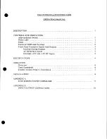
Page 4: ...tion LEDS and Switches 2 Front Edge Connector Inputs And Outputs 3 Synchro Analog Outputs 3 AC Reference Inputs 3 External 15V and 15V DC Inputs 3 SPECIFICATIONS 4 OPERATION Overview 6 Card Commands 6 Synchro Output Polarity Convention 7 INSTALLATION 8 APPENDIX A 53 63 SERIES SYSTEM COMMANDS 9 APPENDIX B INPUT OUTPUT CONNECTIONS 1 0 ...

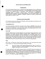
Page 5: ...rogrammer a visual indication of the action which the system is currently taking Whenever the 53A 570 is addressed by the system controller the Power LED goes out T h e LED remains out until another function card is addressed Since only one function card can be addressed at a time an unlit Power LED indicates the function card with which the system controller is currently communicating T h e Power...

Page 6: ...wing switches are provided to select the proper functions for the 53A 570 Card s operating environment Halt Switch This two position slide switch is located near the card s backplane edge connector I t selects the state of the 53A 570 Card after an XH Halt or STOP command is received by the 53 63 Series System a I f the Halt Switch is in the ON position then the 53A 570 Card is reset to its power ...

Page 7: ...g the synchro outputs with an oscilloscope the oscilloscope ground not be hooked to any of the outputs M a k e a differential measurement with two channels of the oscilloscope instead Although the outputs are isolated and any one signal can be connected to ground multiple outputs can accidentally be shorted causing severe damage to the card External I 5V and I5V DC Inputs A 53A 062 internal 15V DC...

Page 8: ...26V RMS nominal Input impedance 25 kohms minimum Output Output format S y n c h r o Output voltages V RMS phase referenced to Ref Hi Ref Lo S3 S1 11 8 sin 0 in phase 52 S3 11 8 sin 0 sin 1200 in phase S1 S2 11 8 sin 0 sin 240 in phase Output current maximum per channel 2 Volt amperes Programmed By A S C I I characters Power Reauirements 5 V and 15V dc power is provided by the internal Power Supply...

Page 9: ...C 197 mm high 220 mm deep 13 mm wide 7 5 x 8 66 x 0 8 When ordered with a 53 63 Card Cage the card is installed in one of the card cage s function card slots When ordered alone the shipping dimensions are 254 mm x 254 mm x 127 mm 1 0 x 10 x 5 0 50 kg 1 1 lbs When ordered with a 53 63 Card Cage the card is installed in one of the card cage s function card slots When ordered alone the shipping weigh...

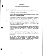
Page 10: ...tion card is addressed Card Commands The 53A 570 Card commands are as follows zA zB This command sets channel A to the output value specified by Z where z represents a one to six digit decimal number in the range 0 to 999999 With the period this number represents a fraction of 360 I f z is not specified the output value defaults to zero This command sets channel B to the output value specified by ...

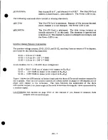
Page 11: ...an output of 0 in degrees are found by the following equations S3 S1 11 8 sin 0 V RMS S2 S3 11 8 sin 0 120 V RMS SI S2 11 8 sin 0 240 V RMS As an example for 0 246 3620 these voltages are SI S3 10 81V RMS out of phase with respect to RHI RLO S2 S3 1 31V RMS in phase with respect to RHI Rw SI S2 9 5 0 V RMS in phase with respect to RHI Rw Figure 1 shows the differential reference input and the thre...

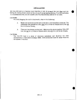
Page 12: ...owing a M a t c h the keyed slot on the card to the key in the backplane connector The component side should be to the right for a 53 Series Chassis and to the top for a 63 Series Chassis b T h e r e are two ejectors on the card Make sure the ejector marked 53A 570 is at the toD for a 53 Series Chassis and to the left for a 63 Series Chassis CAUTION The 53A 570 Card is a piece o f electronic equip...

Page 13: ...all cases if addressed Power LED Out the 53A 570 will become unaddressed Power LED Lit when a Halt command is received On the 53A 570 Card the position of the Halt switch causes the XH command to have the following effect I f the Halt switch is ON the 53A 570 Card resets to its power up state i f the Halt switch is OFF the 53A 570 Card is simply unaddressed STOP T h e STOP command is not a string ...

Page 14: ... A 5 R H I reference input high channel A 6 R L O reference input low channel A 10 S i synchro analog output channel B 1 1 S 2 synchro analog output channel B 12 S 3 synchro analog output channel B 13 R e s e r v e d S4 resolver channel B 14 R H I reference input high channel B 15 R L O reference input low channel B 23 24 1 5 VDC External Power Supply Input A Z G R O U N D AA BB 1 5 VDC External P...

Page 15: ... 9 C o l o r a d o D a t a S y s t e m s I n c A l l r i g h t s r e s e r v e d Contents o f t h i s p u b l i c a t i o n may n o t b e r e p r o d u c e d i n a n y form w i t h o u t t h e w r i t t e n p e r m i s s i o n o f C o l o r a d o D a t a S y s t e m s I n c ...

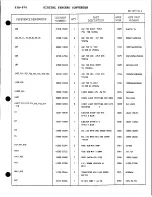
Page 16: ...000 05260 2 DIODEZENER 43V 5W 5 0074 1N5260B DS01 32000 00103 1 DIODELIGHT EMITTING RED50MA 0039 550 0103 DS011 012 013 014 015 016 017 32000 02003 8 DIODELIGHT EMITTING RED WITH 0039 547 2003 018 RESISTOR 0 El 40401 00570 1 EJECTORSTAMP 53A 570 0026 40401 00570 STYLE B BLUE E2 40401 10058 1 EJECTORSTAMP D S 0026 40401 10058 STYLE D BLUE E3 45050 03293 1 DCLLED 8POSDRW 00000 00564 0026 45050 03293...

Page 17: ...13 00062 1 PROGRAMMEDPROM U04 0026 79813 00062 53A 570 UO5 36 57 66 86 76901 07402 5 IC TTL LS QUAD 2 INPUT 0107 74LS02 NORGATE U06 84 76500 07410 2 IC TTL LS TRIPLE 7 TwIPUT 0107 74LS10 NANDGATE U07 87 78401 07414 2 IC TTL HEX SCHMITT INVERTING 0107 7414 BUFFER U15 77 85 77815 07432 3 IC TTL LS QUAD 2 INPUT OR GATE 0107 74LS32 U16 26 76510 07411 2 IC TTL ALS TRIPLE 3 INPUT 0107 74ALS11 AND GATE U...

Page 18: ...U56 79001 07442 1 IC TTL LS 4 LINE TO 10 LINE 0107 74LS42 DECODER U67 76 77203 07408 2 IC TTL ALS QUAD 2 INPUT 0107 74ALSO8 ANDGATE U74 79813 00064 1 PROGRAMMEDPROM U74 0026 79813 00064 53A 570 U96 97 73001 07474 2 IC TTL LS DUAL D TYPE EDGE 0107 74LS74A TRIG FLIP FLOP X01 02 45010 08100 2 SOCKET SIP 8 PIN 0032 CAS 08VSC 126 X04 24 74 45012 24100 3 SOCKET 24 PIN DIP 0089 ICN 246 S5 G D I G I TA L ...

Page 19: ...6 U34 U35 U36 U44 U45 U46 U54 U55 U56 U64 U65 uss Ce6 M S S I C U74 X74 U75 U76 RIM U84 U85 U86 Q 841 Qr9 12 U9S U96 E s X 1 3 1 X 0 2 l t D6i1I 0663 2 DISel 3 D b a i D S O P NOM DM CO3 UO3 O U30 Fun I FS62l U G O 0 I raei1 IF932 1 41530 57000 8911 06 C ...

Page 20: ...I 991577 SI 994n r 6 r 0 0 0 0 0 0 0 0 0 C 2 C I C C C D n w 11 1 J r CD ICT r ry J ...

Page 21: ...1 01 4 3 7 o2 7411 13 6 3 15 7 7414 C 11 9244 2 17 1 LAG f 24 TDPI 1 017 2 7414 3 5 1 P 0 E r 6 7414 7 0 Er 7414 U17 11 12 9 1 6 3 16 017 7139 13 7419 LS U1 16 7419 LS 7414 Is 7492 L S 3 1 L577 4 0 2 0 _ 1 0 L s 2 4 5 U C C 7492 LS I I 7414 ...

Page 22: ...t f Ls a 741_942 g CR74 9 LS 7115175 ID I Q 2D 2 0 3D 3 Q La 4 0 4 Q U35 CLA I 2 4L5175 U I Q 2D 2 0 35 10 4 5 WS MP a 2 C l 2 1115175 10 I Q 2D 2 0 30 3 Q 40 I S U25 C O O I 7115175 ID I Q 29 2 5 3D 3 Q 40 4 1 1 155 CIA 1 7 L5175 20 2 5 30 3 5 D I Q 4D 4 4 UTS _ s 2 Ds99 ...

Page 23: ...CLRRLL U 7 6 2 7108 FLS Isy66 ENT 7 L 1 0 2 ULDDIG s m 13 FL OR BL 1 177 11 0DP 9 J 7L4 32 U77 2 7132 LS 3 STOP U97 CP 7 LS71 ro 18 U67 718e RLS ...

Page 24: ...LATCH c _ i 1 _ 0 5 f 2 L L i i m I LATCH E A 776 flC 12 NIO Iw L l 2 12Cie 4 4 13 ...

Page 25: ...4 C S I B3 5 3 82 5 2 B1 S I 74L5293 RI 13 Al U11 C O 7 4 s a 83 5 3 02 5 2 B 1 e l m s2e3 BI 1154 C O 1 B1 C I S i Rt 5 3 02 5 2 SI S I 70 5263 SI A3 U 6 4 RI CS 06C51111 IS 12 13 11 IS 16 HOE SI 52 63 FL 4 I t 1511 15 1 U la IS 16 1495 52 53 610 ft OPTION 001 016 12 C 1 4 5 3 1 6 MIN U U 10 11 1 2 G M ...

Page 26: ... LEVEL REVISION LEVEL ECO P ART NO 8903 06 R 962 8606 02 B 416 53A 570 8910 06 B 1136 8606 02 C 428 3 1 1 4 9 8911 06 C 1137 8606 02 D 432 COLORADO DESCRIPTION 8607 03 R 429 DATA DIGITAL SYNCHF 8706 03 B 561 SYSTEMS CARD 8707 04 R 563 8707 04 B 729 P C B NUMBER 8707 05 R 961 11530 57000 G N D C91 015 CI4 CIS C9S C9 1 C95 C ...

Page 27: ...quipment Have surplus equipment taking up shelf space We ll give it a new home Learn more Visit us at artisantg com for more info on price quotes drivers technical specifications manuals and documentation Artisan Scientific Corporation dba Artisan Technology Group is not an affiliate representative or authorized distributor for any manufacturer listed herein We re here to make your life easier How...

Reviews: