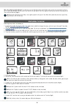
COMAC C85 2018 BS NSC BASIC, Use And Maintenance Manual
The COMAC C85 2018 BS NSC BASIC comes with a comprehensive Use And Maintenance Manual, providing users with all the necessary information for smooth operation. Quickly and easily download this manual for free from our website, ensuring a hassle-free experience with your COMAC C85.
Share
Download


Reviews:
No comments
Related manuals for C85 2018 BS NSC BASIC

1108
Brand: Janome Pages: 59

109
Brand: Janome Pages: 42
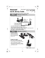
KX-TG5480
Brand: Panasonic Pages: 8

5274
Brand: National Flooring Equipment Pages: 12

OF5700
Brand: Oki Pages: 16

9200D
Brand: Janome Pages: 42

Ellageo PLUS BLL2
Brand: Baby Lock Pages: 48

9143
Brand: Singer Pages: 51

KM 150/500 R D 4W
Brand: Kärcher Pages: 420

GBC/VeloBind System Three Pro
Brand: Officezone Pages: 7

MK740DSA
Brand: Merrylock Pages: 36

DLN-6390
Brand: JUKI Pages: 380

P-1800
Brand: Koblenz Pages: 14

KX-PW30CL
Brand: Panasonic Pages: 12

KX-PW308DL
Brand: Panasonic Pages: 20

KX-PW201CL
Brand: Panasonic Pages: 24

KX-PW301DL
Brand: Panasonic Pages: 32

KXF1000 - FAX
Brand: Panasonic Pages: 80


