


Cop
yright ©2014 Goodman Manufacturing Co
mpany, L.P.
RT6612031
September 2014
This manual is to be used by qualified, professionally trained HVAC technicians only. Goodman does
not assume any responsibility for property damage or personal injury due to improper service
procedures performed by an unqualified person.
•
Refer to Service Manual RS6612009 for installation, operation, and troubleshooting information.
•
Refer to the appropriate Parts Catalog for part number information.
•
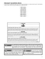
Models listed on page 3.
TECHNICAL MANU
TECHNICAL MANU
TECHNICAL MANU
TECHNICAL MANU
TECHNICAL MANUAL
AL
AL
AL
AL
TM
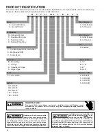
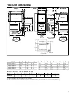
*CVC97/*MVC97
97% Gas Furnace Units


