background image

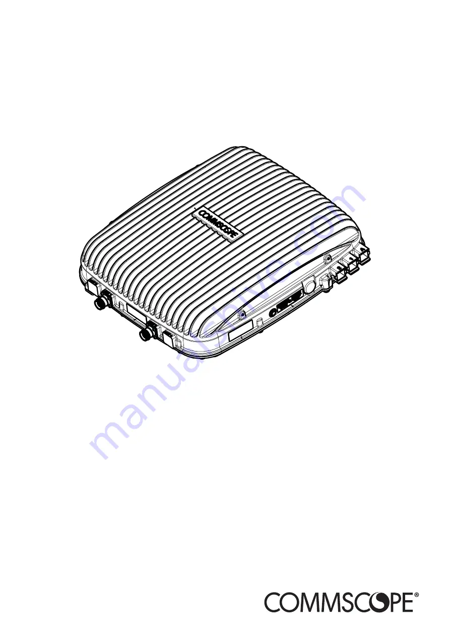
CommScope Era

Fiber Low Power Carrier Access Point

Installation Guide  •  M0201ANC_uc  •  June 2019

Summary of Contents for Era

Page 1: ...CommScope Era Fiber Low Power Carrier Access Point Installation Guide M0201ANC_uc June 2019 ...

Page 2: ...sturbed conditions Should further information be desired or should particular problems arise which are not covered sufficiently for the purchaser s purposes contact CommScope CommScope reserves the right to change all hardware and software characteristics without notice COPYRIGHT 2019 CommScope Inc All Rights Reserved This document is protected by copyright No part of this document may be reproduc...

Page 3: ...ber Splice Box Kit 20 Mounting Dimensions for a CAP L Mounted with the AC DC Power Supply Kit 21 CAP L Weights 21 Extended CAP L Temperature Operation 22 Recommended Tools and Material 23 Unpack and Inspect the CAP L and Optional Accessories 23 Obtain the Required Materials 23 Mount the Fiber CAP L 24 General Mounting Cautions 24 Mounting a CAP L with a Flat Mounting Bracket Kit 25 Attach the Flat...

Page 4: ...EN 60 Cascade a Secondary Fiber CAP L Optional 61 Connect an External Ethernet Device Optional 62 Connect to Vdc Power 62 Powering on a Fiber CAP L 62 CAP L Maintenance 63 Remove a CAP L from a Wall or Ceiling Mount 63 Preventative CAP L Maintenance for CAP Ls with the Fan Kit Option 63 Contacting CommScope 64 CMS Global Technical Support 64 Telephone Helplines 64 Online Support 64 Waste Electrica...

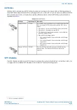
Page 5: ...s installation guide supports Table 1 Supported CAP L Models Part Number 1 Model Name 7770203 000x CAP L 17E 17E 23 23 7770209 000x CAP L 18 21 26 26 7770356 000x CAP L 17E 17E 19 19 7776595 000x CAP L 9 18 18 21 7776596 000x CAP L 7 80 85 17E 19 7776597 000x CAP L 17E 19 23 25TDD 7776598 000x CAP L 9 18 21 26 7776641 000x CAP L 8 9 18 21 7776643 000x CAP L 8 18 21 26 1 The 000x suffix provides in...

Page 6: ...onal injury induce a safety problem in a managed device destroy or corrupt information or interrupt or stop services The icon to the left indicates a caution or warning that pertains to laser equipment The icon to the left indicates a caution or warning that pertains to Radio Frequency RF The icon to the left indicates that the hardware is susceptible to Electro Static Discharge ESD damage The ico...

Page 7: ...m Decibel milliwatts OPT Optical Transport DC Direct Current PN Part Number DCCS Distributed Coverage and Capacity Solutions RAN Regional Area Network EFTA European Free Trade Association RF Radio Frequency EMC Electromagnetic Compatibility RU Rack Unit EMEA Europe Middle East Africa SFP Small Form Factor Pluggable EU European Union SMF Single Mode Fiber F Fahrenheit TEN Transport Expansion Node F...

Page 8: ...tecture in their hubs All operator Baseband signals analog BTS and BBU CPRI are supplied to the Switching CAN by the WINs so no RFD or CDD Cards can be installed in the Switching CAN The Switching CAN then combines the signals from all WINs and distributes those signals to the TENs and the TENs provide the signals to the APs APs are not directly connected to a Switching CAN Users have full and fle...

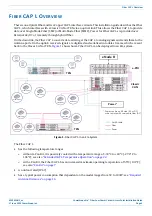
Page 9: ...data streams which are sent back to the Classic CAN or TEN Figure 1 shows how a Fiber CAP L can be deployed in an Era system e POI Classic CAN eNode B TEN UAP UAP UAP UAP Power can be on AP side AC or DC or be remote with composite fiber DC TEN Cat6A cable Fiber Power Power Fiber CAP L Fiber CAP L Fiber CAP L Fiber CAP L Fiber CAP L Fiber CAP L Fiber CAP L Fiber CAP L Fiber CAP L Fiber CAP L Figur...

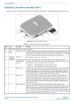
Page 10: ...t 2 If the CAP L is functioning as a Primary CAP L in a cascade Optical Port 2 connects to Optical Port 1 of the Secondary CAP L via the Optical OCTIS Kit PN 7770612 which ships with the unit to provide the main signal interface Optical transport occurs over Single Mode Fiber SMF or Multi Mode Fiber MMF Port 2 ships with factory installed EMI weatherproof plug and must remain plugged if not in use...

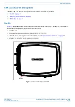
Page 11: ...d Power Kits on page 8 OCTIS Kits on page 9 Fan Kit Figure 3 shows the optional Fan Kit that is an integrated shroud that fits over a Fiber CAP L enclosure to extend the upper ambient temperature range The Fan Kit is IP55 rated increases the maximum operating temperature to 55 C 131 F adds 3W power consumption to the Fiber CAP L see Required Antenna Distances on page 16 is factory installed but ca...

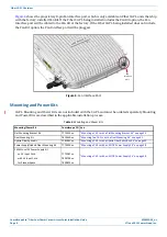
Page 12: ... Mounting and Power Kits are not included with the CAP L and must be ordered separately Mounting and Power Kits are described in the applicable installation process Table 3 Mounting and Power Kits Mounting Power Kit CommScope PN See Flat Mounting Bracket Kit 7774353 xx Mounting a CAP L with a Flat Mounting Bracket Kit on page 25 Dual Mounting Kit 7815440 xx Mounting Two CAP Ls with a Dual Mounting...

Page 13: ...t ships with each Fiber CAP L Use as follows Optical Port 1 to connect the CAP M to a Classic CAN or TEN Optical Port 2 to cascade a second CAP M SFP Module must be ordered separately it is not included as part of the Optical OCTIS Kit Ships with the following grommets 6mm nominal diameter for use with cables with OD range from 4 8 5 8 7mm nominal diameter for use with cables with OD range from 5 ...

Page 14: ...imensions on page 18 5 Map out all cable runs 6 Identify and obtain all tools and materials required to complete the installation as described in Recommended Tools and Material on page 23 7 Obtain any accessories required for this installation see CAP L Accessories and Options on page 7 8 Unpack and Inspect the CAP L and Optional Accessories on page 23 Maximum Number of Fiber CAP Ls Supported in a...

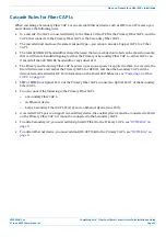
Page 15: ... the 320 MHz RF bandwidth or any subset of it The Primary and Secondary Fiber CAP Ls power up as soon as power is applied to them In a cascade the Era GUI discovers and readies the Primary CAP L for RF first and then the Secondary CAP L will be discovered and readied for RF For information on the Power LED behavior see Powering on a Fiber CAP L on page 62 SMF or MMF from Optical Port 2 of the Prim...

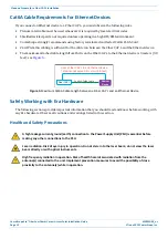
Page 16: ... 5 From a Fiber CAP L to an Ethernet device Cat6A cannot exceed 3 meters 9 8 feet 24 AWG Cat6A Cable Fiber CAP L Ethernet Device Figure 5 Maximum Cat6A Cable Length between a Fiber CAP L and an Ethernet Device Safely Working with Era Hardware The following sections provide important information that you should read and know before working with any Era hardware Observe all cautions and warnings lis...

Page 17: ...l shock when installing or using electrically powered equipment To prevent electrical shock never install or use electrical equipment in a wet location or during a lightning storm This system is a RF Transmitter and continuously emits RF energy Maintain a minimum clearance from the antenna as specified in Table 6 while the system is operating Whenever possible power down the CAP L before servicing...

Page 18: ... 300 GHz 3 Notice Installation of this equipment is in full responsibility of the installer who has also the responsibility that cables and couplers are calculated into the maximum gain of the antennas so that this value which is filed in the FCC Grant and can be requested from the FCC data base is not exceeded The industrial boosters are shipped only as a naked booster without any installation de...

Page 19: ...ur pour satisfaire la conformite aux expositions RF 5 Notice The unit complies with Overvoltage Category II It also complies with the surge requirement according to EN 61000 4 5 fine protection however installation of an additional medium via local supply connection and or coarse protection external surge protection is recommended depending on the individual application in order to avoid damage ca...

Page 20: ...es in excess of 100 000 for each continuing violation For Part 90 signal booster WARNING This is NOT a CONSUMER device It is designed for installation by FCC LICENSEES and QUALIFIED INSTALLERS You MUST have an FCC LICENSE or express consent of an FCC Licensee to operate this device You MUST register Class B signal boosters as defined in 47 CFR 90 219 online at www fcc gov signal boosters registrat...

Page 21: ...ypical Power W Maximum Power W Fiber CAP L without Fan Kit 1 2 36 60 92 102 Fiber CAP L with Fan Kit 1 2 36 60 95 107 1 Does not include consumption of optional local DC supply 2 Optical unit does not include SFP Module consumption Can support up to 3W more with engineering consultation maximum total SFP Module consumption Typical installation sufficient for SM up to 10km or MM would be 0 8W typic...

Page 22: ...Use the dimensions shown in the section applicable to this installation to determine the space required at the mounting site Mounting Dimensions for a CAP L with the Flat Mounting Bracket Kit 120mm 4 72 42 75mm 1 68 30mm 1 18 24 11mm 0 95 440mm 17 32 406mm 15 98 144mm 5 67 205mm 8 07 10mm 0 39 4X 383 34mm 15 09 512mm 20 16 393 13mm 15 48 2X 30 5mm 1 2 114 28mm 4 5 125 25mm 4 93 ...

Page 23: ... Installation Guide June 2019 CommScope Inc Page 19 Plan and Prepare for a Fiber CAP L Installation Mounting Dimensions for Two CAP Ls Mounted with the Dual Mounting Kit 325mm 12 8 448mm 17 64 486mm 19 13 454mm 17 87 10mm 0 394 4X 274mm 10 79 538mm 21 2 247mm 9 72 ...

Page 24: ...ope Inc Plan and Prepare for a Fiber CAP L Installation Mounting Dimensions for a CAP L Mounted with the CAP L Hybrid Fiber Splice Box Kit 120mm 4 72 188mm 7 4 383 34mm 15 09 512mm 20 16 2X 30mm 1 18 424 53mm 16 71 390 33mm 15 37 24mm 0 94 2X 460 75mm 18 14 116 3mm 4 58 31 5mm 1 24 170 19mm 6 7 36 75mm 1 45 ...

Page 25: ...ighest weight that must be lifted during installation An installer only needs to lift CAP L components at one time not the wholly configured CAP L The Total Hanging Weight is the weight of the CAP L including the weight of the Mounting Bracket and Power Supply minus the weight of the external cables and connectors that the mounting site must be able to support Table 8 Maximum CAP L Installation We...

Page 26: ...lowed temperature The CAP L will disable itself if any of the internal temperatures exceeds the maximum allowed temperature The maximum ambient temperature of the CAP L is dependent on the mounting configuration as the mounting configuration affects the ability of the CAP L to dissipate heat The various mounting configurations and resulting temperature ranges of operation are detailed in Table 9 T...

Page 27: ...ed for this installation Obtain the cable required for this installation Per the installation plan obtain either Single Mode Fiber SMF or Multi Mode Fiber MMF that is of sufficient length to reach from the CAP L to the Classic CAN or TEN In a cascade the Primary Fiber CAP L connects to the Classic CAN or TEN If you are cascading a Secondary Fiber CAP L to the Primary Fiber CAP L you also need a su...

Page 28: ...P L Using a Flat Mounting Bracket Kit on page 30 Mounting Two CAP Ls with a Dual Mounting Kit on page 31 Mounting a CAP L with an AC DC Power Supply Kit on page 38 Mounting a CAP L with a Hybrid Fiber Splice Box Kit on page 43 Ceiling Mount a CAP L on page 54 Ceiling Mount a CAP L without a Fan Kit on page 54 Ceiling Mount a CAP L with a Fan Kit on page 54 General Mounting Cautions The following c...

Page 29: ...iber CAP L Mounting a CAP L with a Flat Mounting Bracket Kit Figure 6 shows the Flat Mounting Bracket Kit CommScope PN 7774353 xx which provides the mounting brackets required to mount a Fiber CAP L to a wall or other flat surface Six M6 1 0 x 14 mm screws Two Moun ng Brackets Figure 6 Flat Mounting Bracket Kit PN 7774353 xx ...

Page 30: ...o and observe all cautions listed in General Mounting Cautions on page 24 3 Use three of the M6 1 0 x14mm screws that came with the Flat Mounting Bracket Kit to attach the left or top mounting bracket to the three corresponding horizontal or vertical M6 1 0 mounting taps on the back of the CAP L chassis 4 Use three of the M6 1 0 x14mm screws that came with the Flat Mounting Bracket Kit to attach t...

Page 31: ...ing or any other horizontal surface that allows stable placement Do the following to flat surface mount a Fiber CAP L 1 Use Plan and Prepare for a Fiber CAP L Installation on page 10 to identify the installation site and installation requirements and to prepare for this installation 2 In addition to the cautions listed in General Mounting Cautions on page 24 observe the rules that are specific to ...

Page 32: ...ing efficiency as shown in the preceding graphic Cooling efficiency is reduced when the enclosure fins are facing down a fan kit is recommended for maximum service life when the CAP L is mounted in this orientation For further details on installation without a fan kit see Extended CAP L Temperature Operation on page 22 If you are mounting the CAP L above a ceiling its antennas must protrude below ...

Page 33: ...s When wall mounting a Fiber CAP L the recommendations should be observed Wall Mount Orientation for a CAP L without a Fan Kit A CAP L that does not have a Fan Kit is passively cooled You should therefore mount a CAP L that does not have a Fan Kit with the ANT ports pointing down see Figure 9 Otherwise the CAP L will have a reduced maximum operating temperature of 33 C 91 F ANT connectors poin ng ...

Page 34: ...hown Mounting requirements for flat surfaces are described in Flat Surface Mount a CAP L on page 27 Ceiling mount requirements are described in Ceiling Mount a CAP L with a Fan Kit on page 54 Wall Mount a CAP L Using a Flat Mounting Bracket Kit 1 Use Plan and Prepare for a Fiber CAP L Installation on page 10 to identify the installation site and installation requirements and to prepare for the ins...

Page 35: ...rface follow the steps in Ground the Fiber CAP L Optional on page 55 if grounding is required or preferred Connect the Passive RF Antenna on page 59 Mounting Two CAP Ls with a Dual Mounting Kit Figure 11 shows the Dual Mounting Kit CommScope PN 7815440 xx The Dual Mounting Kit is capable of mounting two CAP Ls with or without fan kits 1 2 3 4 5 Ref Quantity Component 1 4 Nylon Cable Clamps preatta...

Page 36: ...CAP Ls Back to Back in a Dual Mounting Bracket Do the following to mount two Fiber CAP Ls in a Dual Mounting Bracket 1 Use Plan and Prepare for a Fiber CAP L Installation on page 10 to identify the installation site and installation requirements and to prepare for the installation 2 Refer to and observe all cautions listed in General Mounting Cautions on page 24 3 Refer to Determine the CAP L Inst...

Page 37: ...the Dual Wall Mount Bracket using 4 M8 or 5 16 screw anchors not included or suitable lag bolts according to the drilling layout as shown below The M6 screw anchors do not ship with the CAP L as the anchor type is dependent on the on site conditions wall structure and materials Use screw anchors that are rated for the mounting surface 10 00 mm 394 4X 454 00 mm 17 874 274 00 mm 10 787 b Confirm tha...

Page 38: ...ber CAP L 6 Use the six M6 1 0 x14mm screws that came with the Dual Mounting Bracket Kit to attach the two Mounting Adapters three screws per bracket to the vertical M6 1 0 mounting taps on the back of the CAP L 1 chassis three taps per side Three M6 1 0 x 14mm screws Moun ng Adapter Three M6 1 0 x 14mm screws Moun ng Adapter ...

Page 39: ...2019 CommScope Inc Page 35 Mount the Fiber CAP L 7 Insert an M8x16 screw in the top screw hole on the left Mounting Adapter attached to CAP L 1 and then insert screw three or four turns M8x16 screw M8x16 screw Moun ng Adapter Moun ng Adapter 8 Repeat Step 7 for the right Mounting Adapter ...

Page 40: ...and Step 8 on page 35 with the Mounting Bracket slots that are closest to the mounting surface b Insert an M8x16 screw into the bottom screw hole of the Dual Wall Mount Bracket that is closest to the mounting surface and into the bottom screw hole on each CAP L 1 Mounting Adapter c Tighten all four M8x16 screws to secure the CAP L 1 to the Dual Wall Mount Bracket torque to 13 5 N m 120 in lb M8x16...

Page 41: ...ollowing graphic 10 Repeat Step 6 on page 34 through Step 9 on page 36 to mount the CAP L 2 chassis in the Dual Wall Mounting Bracket install the CAP L 2 chassis back to back with the CAP L 1 chassis as shown Figure 12 on page 32 11 After you mount the two CAP Ls in a Dual Mounting bracket follow the steps in Ground the Fiber CAP L Optional on page 55 if grounding is required or preferred Connect ...

Page 42: ...e also CommScope Part Numbers on page 3 2 Refer to and observe all cautions listed in General Mounting Cautions on page 24 3 Refer to Determine the CAP L Installation Site on page 17 to determine the mounting location which must be able to support the weight and dimensions of the CAP L 4 Refer to Mounting Orientation for Wall Mounts on page 29 to determine the mounting orientation of the CAP L 5 F...

Page 43: ...09823 xx Not for outdoor use M0201ANC_uc CommScope Era Fiber Low Power Carrier Access Point Installation Guide June 2019 CommScope Inc Page 39 Mount the Fiber CAP L Figure 14 CommScope Local AC DC Power Supply Kits To insert and connect the AC input cord for kit number 7775087 xx and kit number 7809823 xx do the following 1 Remove the four Phillips head screws from the left junction box cover of t...

Page 44: ...s to secure it 6 Mount the AC DC Power Supply Kit to the CAP L mounting bracket Due to derating requirements each CAP L must have its own PSU no sharing is permitted 7 Assemble and mount the AC DC Power Supply Kit and the CAP L as described below and as shown in Figure 17 on page 41 CAP L without Fan Kit and Figure 18 on page 42 CAP L with Fan Kit The Local Power Jumper Cable Assembly will be conn...

Page 45: ...Local Power Jumper Cable M0201ANC_uc CommScope Era Fiber Low Power Carrier Access Point Installation Guide June 2019 CommScope Inc Page 41 Mount the Fiber CAP L Figure 17 CAP L No Fan Kit with AC DC Power Supply Kit PN 7775087 xx and Power Supply Hybrid Fiber Mounting Kit 7774354 xx The Power Supply Hybrid Fiber Mounting Kit is not included with the CAP L and must be ordered separately ...

Page 46: ...an Kit AC DC Power Supply Kit PN 7775087 xx and Power Supply Hybrid Fiber Mounting Kit PN 7774354 xx 8 Connect the Local Power Jumper Cable shown below to the CAP L 36 to 60 Vdc Power connector see Figure 2 on page 6 Local Power Jumper that connects to CAP L 36 to 60 Vdc Power connector Gland for incoming AC power Local Power Jumper that connects o CAP L 36 to 60 Vdc Power connector ncoming AC pow...

Page 47: ...rvice provider and to comply with Limited Power Source LPS requirements where applicable Prepare for CAP L Hybrid Fiber Splice Box Kit Installation 1 Follow the steps in Unpack and Inspect the CAP L and Optional Accessories on page 23 2 Refer to Determine the CAP L Installation Site on page 17 to determine the mounting location which must be able to support the weight and dimensions of the CAP L 3...

Page 48: ...Fiber Splice Box and remove the installation kit that is inside 2 Using the parts from the Hybrid Fiber Splice Box insert the Splice Holder and fasten it using a PTK 30x6 screw and one M4 washer 3 From the CAP L Hybrid Fiber Splice Box Kit insert Fiber Patch Cord in one of the cable glands indicated in the graphic to the right 4 Strip the insulation of the composite cable for 100 cm and the fibers...

Page 49: ...s action The cable must be fed through the nut and it must be retightened once finished 6 Bend the spliced fibers using the corner guides and fix the splices to the splice holder 7 Bend the optical cables as shown in the picture to the right 8 If a second splice holder is needed it can be assembled using the M4 insulating washer and two M4 plain washers as shown to the right The required screw is ...

Page 50: ...bles inside the box using one cable tie and tight the sealing nut 13 It is possible to separate the optical cables and use two different cable glands Remove the sealing nut and rubber on each cable gland 14 Close all unused grooves with the plastic cylinders no matter if one or two cable glands are used 15 Insert the copper wires in the first multiple terminal connectors See markings on the intern...

Page 51: ...om the Hybrid Fiber Splice Box to a DC Power Supply Unit PSU The color code of the hybrid fiber cable in the following tables and diagrams is for example purposes only The color of the wires may be different than the examples depending on the type and manufacturer of the composite hybrid cable 16 Remove the sealing nut and insert the CAP L supply cable and tighten the sealing nut 17 Connect the su...

Page 52: ...h LPS Hybrid Cable Two Circuits CAP L Power Cable Connector Wire Wire Pin Function Circuit 1 0V Red 1 V1 Circuit 1 36 to 60V Black 2 V1 Circuit 2 0V White 3 V2 Circuit 2 36 to 60V Green 4 V2 Pin 1 Pin 2 Pin 4 Pin 3 Connector End View PIN 1 RED PIN 2 BLACK PIN 3 WHITE PIN 4 GREEN Hybrid Fiber Composite cable Color code of hybrid cable may differ from example shown Figure 19 Wiring a Hybrid Fiber Spl...

Page 53: ...er Source LPS In this power variation you must tie the following power cables together V1 PIN 1 and V2 PIN 3 CAP L DC Jumper Power Cable Red and White wires V1 PIN 2 and V2 PIN 4 CAP L DC Jumper Power Cable Black and Green wires Table 11 Wiring Single Circuit Source to a CAP L Source Cable CAP L Power Cable Connector Wire Wire Pin Function Circuit 1 0V Red 1 V1 White 3 V2 Circuit 1 36 to 60V Black...

Page 54: ...id Fiber Splice Box to Cascade Two CAP Ls with the 2 Wire Power Configuration Figure 21 shows a variation of the 2 Wire power configuration that allows you to cascade two CAP Ls using a single 4 wire hybrid cable All four pins of the proprietary CAP L 4 pin 36 to 60 Vdc Power connector must be terminated Hybrid Fiber Composite cable One wire each for the Main and Secondary CAP L in the cascade Fig...

Page 55: ...uration Figure 22 shows a variation of the 4 Wire power configuration that allows you to cascade two CAP Ls using two 4 wire hybrid cables All four pins of the proprietary CAP L 4 pin 36 to 60 Vdc Power connector must be terminated Hybrid Fiber Composite cable One wire each for the Main and Secondary CAP L in the cascade Figure 22 Wiring a Hybrid Fiber Splice Box to Cascade Two CAP Ls in a 4 Wire ...

Page 56: ... Fiber Splice Box to the Wall Bracket with the three captive screws already installed in the Splice Box Connect three cap ve screws on Hybrid Fiber Splice Box to Wall Bracket 2 Attach the assembled Wall Mounting Bracket and Hybrid Splice Box to the selected mounting location 3 Use the six M6 1 0 x14mm screws to attach the two Angled Mounting Brackets to the back of the CAP L as shown below Six M6 ...

Page 57: ...two flange head screws with the mounting slots on the Wall Mounting Bracket and then lower the CAP L so that it hangs on the Wall Mounting Bracket 6 Attach the bottom two flange head screws 7 Tighten all four flange head screws 8 Attach the cables running from the bottom of the CAP L Hybrid Fiber Splice Box Kit a Attach the Local Power Jumper to the CAP L power connector b Attach the Fiber Patch C...

Page 58: ... a Fan Kit 1 Follow the steps in Unpack and Inspect the CAP L and Optional Accessories on page 23 2 Refer to and observe all cautions listed in General Mounting Cautions on page 24 3 Refer to Determine the CAP L Installation Site on page 17 to determine the mounting location which must be able to support the weight and dimensions of the CAP L 4 Follow the steps in one of the following sections tha...

Page 59: ...y of the connectors until instructed to do so Ground the Fiber CAP L Optional Follow the steps below to ground the OPA only if grounding is required in your locality or if the installation plans require the CAP L be grounded The different CAP L installation procedures will tell you when to ground the CAP L The CAP L is equipped with an M6 grounding stud located on the back of the unit however grou...

Page 60: ...se the Keps nut removed in Step 4 to secure the ground wire to the chassis ground stud 7 Route the free end of the chassis grounding wire to an approved per local code or practice earth ground source Connect the Fiber CAP L to a Passive RF Antenna The following sections guide you through connecting the CAP M complete these procedures in the order in which they are presented Clean the RF Cable Conn...

Page 61: ...t against injury from flying particles This procedure requires the use of flammable material There is a risk of fire Keep away from sources of ignition This procedure requires the use of eye irritant product There is a risk of eye irritation Avoid contact with eyes and skin Wear protective clothing especially protective glasses Do the following to clean the RF cable connectors 1 Gather the followi...

Page 62: ...ector winding 5 Use a cotton bud drenched with isopropyl alcohol to clean the lip of the inner ring 6 Use a cotton bud drenched with isopropyl alcohol to clean the inside surface of the inner ring 7 Use a cotton bud drenched with isopropyl alcohol to clean the inside of the center conductor spring tines 8 Remove the protective caps from the unit connector and then clean it the same way that you cl...

Page 63: ...n AP0 to antenna port ANT 1 AP1 to antenna port ANT 2 When using SISO channels on a CAP L that supports MIMO the system will automatically balance the number of channels between the two antenna ports where the first SISO channel is mapped to ANT 1 the second SISO channel is mapped to ANT 2 and so on 9 Use compressed air to remove metal chips and small particles from the mating and inner surfaces o...

Page 64: ...lastic protective cap from the 4 3 10 connectors d Remove the IP67 EMI blank plug from the ANT 1 2 connector e Connect the passive multi band antenna to the ANT 1 or ANT 2 connector using coaxial cable with the least amount of loss possible If the 50 coaxial cable has a push pull connector make sure the cable is seated firmly in the ANT 1 or ANT 2 connector If the 50 coaxial cable has a threaded c...

Page 65: ...n Optical Port 2 3 Connect the SMF or MMF to the Primary Fiber CAP L a Remove the cap from the connector on one end of the SMF or MMF b Follow the fiber supplier s recommendations to clean the connectors on the SMF or MMF c Install an SFP Module and Optical OCTIS Kit on the end of the cable that will connect to the Primary CAP L and then connect it to the Optical Port 2 connector on the Primary Fi...

Page 66: ...able to the Ethernet port of the auxiliary device 6 Go to Connect to Vdc Power on page 62 Connect to Vdc Power Connect the Vdc Power connector as appropriate for this installation The CAP L is powered on as soon as you connect the CAP L to a power source see Powering on a Fiber CAP L on page 62 If powering the CAP Ls with local AC DC power adapters please see Wiring the AC DC Power Supply Kit on p...

Page 67: ...the ground wire 3 Reverse the installation steps that correspond to how this CAP L is mounted Preventative CAP L Maintenance for CAP Ls with the Fan Kit Option The CAP L does not require extensive preventative maintenance measures However checking the cleanliness of a CAP L that has the Fan Kit option at regularly scheduled intervals is recommended particularly the enclosure vents which helps main...

Page 68: ...Helpline Online Support To go to the CommScope Wireless Support Request web site from which you can initiate a Technical Support ticket do one of the following Scan the QR Code to the right If viewing this document online as a PDF click on the following URL link http www commscope com wisupport Enter the preceding URL into your web browser and then press ENTER on your keyboard Waste Electrical and...

Page 69: ...n separate course panels for further information on a course click its Full details button Instructor led courses are conducted in North America and Europe Before choosing a course please verify the region 3 To view the course schedule and register click Course Registration at the top of the course page this opens the Partner Learning Center Login page If you have an account enter your Username an...

Page 70: ...ively you can go to the following web address to access the portal https www mycommscope com 2 Access to the Customer Portal requires a user account and password On the Sign In page do one of the following If you have an account enter your Email address and Password and then click Sign In If you don t have an account click New user registration and follow the prompts 3 Click DCCS to open the site ...

Page 71: ......

Reviews: