background image


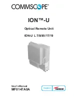
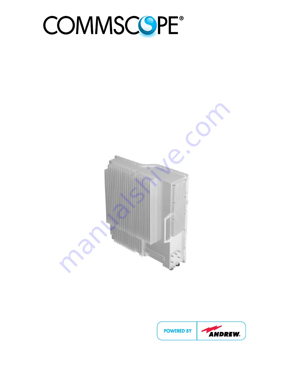
ION™-U 


Optical Remote Unit 


ION-U L 7/8/85/17/19 


User's Manual 

MF0147A0A 


Summary of Contents for ION-U L 7/8/85/17/19

Page 1: ...ION U Optical Remote Unit ION U L 7 8 85 17 19 User s Manual MF0147A0A ...

Page 2: ...the performance under adverse or disturbed conditions Should further information be desired or should particular problems arise which are not covered sufficiently for the purchaser s purposes contact CommScope CommScope reserves the right to change all hardware and software characteristics without notice COPYRIGHT Copyright 2013 CommScope Inc All Rights Reserved This document is protected by copyr...

Page 3: ... PORTS 18 3 COMMISSIONING 20 3 1 MECHANICAL INSTALLATION 20 3 1 1 General 20 3 1 2 Wall Mounting Procedure 21 3 2 ELECTRICAL INSTALLATION 24 3 2 1 General 24 3 2 2 Connections 26 3 2 3 Grounding Earthing 28 3 2 4 Mains Power Connection 29 3 2 5 Antenna Connection 31 3 2 6 Expansion Ports Connections 32 3 2 7 Alarm Port 33 3 2 8 Pwr Ctrl Port 33 3 2 9 Control Connector RS 232 Local Interface 34 3 3...

Page 4: ...EXTERNAL ALARM INPUTS 42 4 5 TROUBLESHOOTING 43 5 MAINTENANCE 44 5 1 GENERAL 44 5 2 RU POWER SUPPLY REPLACEMENT 45 6 APPENDIX 49 6 1 ILLUSTRATIONS 49 6 2 ELECTRICAL SPECIFICATIONS 50 6 3 ENVIRONMENTAL AND SAFETY SPECIFICATIONS 50 6 4 MECHANICAL SPECIFICATIONS 50 6 5 SPARE PARTS 51 7 INDEX 52 ...

Page 5: ...17 Expansion ports 33 figure 4 18 Alarm Connector 33 figure 4 19 Pwr Ctrl Connector 34 figure 4 20 RS 232 connector 34 figure 4 21 Remove optics cover 37 figure 4 22 Remove sealing nut 37 figure 4 23 Remove split seal 37 figure 4 24 Insert fiber optic cables through sealing nut 38 figure 4 25 Insert cables through clamp ring 38 figure 4 26 Place cables into split seal 38 figure 4 27 Press split se...

Page 6: ...sses 14 table 4 1 Specified torques 20 table 4 2 ION U L 7 8 85 17 19 Connectors 27 table 4 3 AC power cable 29 table 4 4 DC power cable 29 table 4 5 Vdc 100 power cable 30 table 4 6 Alarm Connector 33 table 4 7 Pwr Ctrl Connector 34 table 4 8 RS 232 connector pin assignment 34 table 5 1 Status LED alarms 42 ...

Page 7: ... Intercept Point 3 rd order ID No Identification Number ION Intelligent Optical Network IP Ingress Protection ISO International Organization for Standardization LED Light Emitting Diode LMT Local Maintenance Terminal LTE Long Term Evolution MIMO Multiple Input Multiple Output MS Mobile Station MU Main Unit NF Noise Figure OTRx Optical Transceiver SRMU Subrack Master Unit PDU Power Distribution Uni...

Page 8: ...7 Warning Make sure access is restricted to qualified personnel 8 Warning Only licence holders for the respective frequency range are allowed to operate this unit 9 Warning Make sure the repeater settings are correct for the intended use refer to the manufacturer product information and regulatory requirements are met 10 Warning Use this equipment only for the purpose specified by the manufacturer...

Page 9: ...in the manual CD that is delivered with the unit 15 Caution Although the remote unit is internally protected against overvoltage it is strongly recommended to ground earth the antenna cables close to the repeater s antenna connectors for protection against atmospheric discharge 16 Caution ESD precautions must be observed Before commencing maintenance work use the available grounding earthing syste...

Page 10: ...17 19 Equipment Symbols Used Please observe the meanings of the following symbols used in our equipment Symbol Compliance Meaning Alert sign to R TTE Symbol Indicates conformity with the R TTE directive 1999 5 EC certified by the notified body no 0700 ...

Page 11: ... at all fabrication stages Finished products leave the factory only after a thorough final acceptance test accompanied by a test certificate guaranteeing optimal operation This product meets the requirements of the R TTE directive and the Declaration of Conformity DoC itself A current version of the CE DoC is included in this manual CD delivered Any updated version of the DoC is available upon req...

Page 12: ...Capacity Solutions DCCS products Rua Guaporanga 49 Praça Seca Rio de Janeiro RJ ZIP 21320 180 Brazil Mail CALA Tech Support for Distributed Coverage Capacity Solutions DCCS products Av Insurgentes Sur 688 Piso 6 Col Del Valle CP 03100 Mexico City Mexico Phone 1 815 546 7154 Cell 55 15 9104 7722 Office Phone 52 1 55 5419 5260 Cell 52 55 1346 1900 Office Fax 55 15 2102 4001 Fax 52 55 1346 1901 E mai...

Page 13: ... 9099 69 930 Fax 33 1 47 89 45 25 E mail wisupport commscope com E mail wisupport commscope com Austria Switzerland Andrew Wireless Systems Austria GmbH CommScope Wireless Systems AG Mail Weglgasse 10 2320 Wien Schwechat Austria Mail Tiergartenweg 1 CH 4710 Balsthal Switzerland Phone 43 1706 39 99 10 Phone 41 62 386 1260 Fax 43 1706 39 99 9 Fax 41 62 386 1261 E mail wisupport austria commscope com...

Page 14: ...th Africa South Africa CommScope Solutions International Inc Branch Andrew Wireless Solutions Africa PTY LTD Mail PO Box 48 78 22 Unit 3206 Floor 32 Jumeirah Business Center 5 Jumeirah Lakes Towers Dubai United Arab Emirates Mail 11 Commerce Crescent West Eastgate Sandton PO Box 786117 Sandton 2146 South Africa Phone 971 4 390 09 80 Phone 27 11 719 6000 Fax 971 4 390 86 23 Fax 27 11 444 5393 E mai...

Page 15: ...a optical fibers 1 5 The ION U L 7 8 85 17 19 Remote Unit The ION U 7 8 85 17 19 is a low power remote unit for Cell700 LMR800 Cell850 AWS and Extended PCS1900 Band Applications The unit is compatible with analog GSM EDGE IS 95 CDMA2000 EVDO W CDMA HSDPA and LTE modulation standards It is used in conjunction with a Master Unit in the ION optical distribution system This system transports multiple ...

Page 16: ...o be levelled as specified in the system configuration The entire system may be monitored remotely via an Andrew OMC This platform uses SNMP protocol and is compliant to X 733 standard Should a sophisticated interface not be required the Master Unit can be directly connected to the alarm interface of a base station via a LAN local area network or its contact relay Features at a glance Full band fu...

Page 17: ...gnals received by the antennas to maintain a good signal to noise ratio RF filtering to reject spurious emissions Automatic Level Control ALC to adjust the RF signal level to meet blocking requirements RF to optical conversion of the signal which is convey to the output optical port 2 1 SISO and MIMO Operation The modular architecture of the ION U 7 8 85 17 19 supports both SISO and MIMO operation...

Page 18: ...figure 2 3 RU Connectors and Status LED Antenna Port The RU has one duplex N female antenna port for transmitting and receiving signals to and from distributed antennas This RF port can be connected directly to an antenna i e using RF jumper cables or through splitters allowing additional antennas to be fed by the RU Status LED The status LED provides a visual warning of an alarm condition The col...

Page 19: ...C models and standard DC models A 7 pin Amphenol connector is used for DC models powered by a duel cable supply Pwr Ctrl Connector The Pwr Ctrl connector supports an optional fan unit The RU provides power and fan speed control to the fan unit and receives alarms from it through this 7 pin Binder connector Alarm connector The RU has two alarm relay inputs that can be used to monitor and report ala...

Page 20: ...o power dissipation the Remote Unit may reach a very high temperature Ensure sufficient airflow for ventilation 5 Note When connecting and mounting the cables RF optical mains ensure that no water can penetrate into the unit through these cables 6 Note Observe all additional rules or restrictions regarding mounting that apply to specific Remote Unit types If any different or additional mounting ma...

Page 21: ...ing layout Confirm that the bracket is securely fastened to the wall The M6 screw anchors are not included as part of the RU delivery because the suitable type depends on the on site conditions wall structure and materials Therefore use screw anchors that are appropriate for the mounting surface figure 3 1 Wall mounting bracket 3 Attach the M6 threaded pins to the Remote Unit on the both sides fig...

Page 22: ...he M6 pins must align with the slots in the bracket to support the RU B0303A8A figure 3 3 RU placed on wall mounting bracket 5 Fasten the lower section of the Remote Unit to the bracket using a washer and a M6x12 screw on both sides Slide a washer over each screw and then insert the screw and tighten it securely M6x12 screw Washer B0303A9A figure 3 4 Install M6x12 screws and washers ...

Page 23: ...d pins that were installed in step 3 and then screw the nut onto the pins on both sides and tighten securely M6 nut Washer B0303AAA figure 3 5 Attach M6 nut to threaded pins 7 Confirm that all screws and nuts have been fastened and the unit is securely mounted to the wall figure 3 6 Completed SISO RU Mount MIMO mounting instructions ...

Page 24: ...provided within easy reach 5 Caution Before connecting or disconnecting the mains connector at the remote unit ensure that mains power supply is disconnected 6 Caution Make sure that an appropriate circuit breaker acting as a disconnect device as required by IEC EN60950 1 and an overcurrent limiting device are connected between mains power and the Remote Unit 7 Caution A connection of the mains su...

Page 25: ... with the surge requirement according to EN 61000 4 5 fine protection however installation of an additional medium via local supply connection and or coarse protection external surge protection is recommended depending on the individual application in order to avoid damage caused by overcurrent 13 Caution Observe the labels on the front panels before connecting or disconnecting any cables ...

Page 26: ...n to a laptop PC DB 9 Female STATUS This LED provides a visual warning of an alarm condition The color of the LED indicates the severity of the alarm LED PWR CTRL This connector supports an optional fan unit The RU provides power and fan speed control to the fan unit and receives alarms from it Binder 712 series 7 pin ALARM This connector provides alarm contacts that are used to monitor and report...

Page 27: ...he OTRx module of the ION U master unit LC APC MAINS Vac Vdc This connector provides the power to RU models that use standard AC 85 to 265 Vac or RU models that use standard DC 60 to 38 Vdc power Amphenol C016 Series 4 Pin MAINS Vdc 100 This connector provides the power to RU models used in locations where the power drawn on each cable must be limited to a maximum of 100 VA Amphenol C016 Series 7 ...

Page 28: ... as shown in figure 3 8 Do not use the grounding connection to connect external devices figure 3 8 Grounding bolt figure 3 9 Grounding bolt schematic view 2 After loosening the hex nut connect the earth bonding cable between the two washers as illustrated in the figures above 3 Then fasten all parts again by tightening the the hex nut 4 Connect the other end of the ground wire to a suitable perman...

Page 29: ... also available as an option The AC power cable is shown in figure 3 10 blue Amphenol 4 Pin female connector Protective Cap 3x end splice brown yellow green B0302ASA RU Mains Connector 4 3 2 1 4 Pin Amphenol C016 Series Pin Name Color 1 Phase Brown 2 Neutral Blue 3 n c n c 4 Ground Yellow Green figure 3 10 AC power cable table 3 3 AC power cable The standard DC power cable is a 3 2 m 10 5 ft 13 AW...

Page 30: ...ations regarding loop impedance voltage drop and methods of installation Make sure to connect the correct voltage to the unit Note Do not connect or disconnect the power cable at the mains connector while power is on Turn off mains power before connecting the power cable at the remote unit then engage mains power again Mains power must be interruptible with an external mains breaker For the mains ...

Page 31: ... plug s protective cover and carefully test the plug with a voltmeter to ensure that the voltage and polarity are correct 6 Once the testing has been completed turn off the circuit breaker 7 Unscrew the protective cover from the Mains connector of the RU 8 Insert the plug into the Mains connector figure 3 13 and tighten the clamping ring until it is hand tight Do not over tighten the clamping ring...

Page 32: ... passive inter modulation PIM distortion attention must be paid to the physical condition of the connector junctions Do not use connectors that show signs of corrosion on the metal surface Prevent the ingress of water into the connector Attach and torque the connectors properly 1 Route the antenna cable from the antenna or splitter to the base of the RU 2 Cut the cable to length and terminate the ...

Page 33: ... the RU until it clicks into place to connect the cable figure 3 15 Expansion ports 3 2 7 Alarm Port The Alarm port provides alarm contacts that are used to monitor and report alarms generated by other equipment The connector is a 5 pin Binder 712 series connector 5 1 B303ALA 5 Pin Binder 712 Series Pin Assignment 1 EXT1_Alarm 2 EXT1_GND 3 n c 4 EXT2_Alarm 5 EXT_GND figure 3 16 Alarm Connector tab...

Page 34: ...rl Connector table 3 7 Pwr Ctrl Connector 3 2 9 Control Connector RS 232 Local Interface This DB 9 female connector is used for external modem communication with a possible extension unit and for local connection with a laptop 1 6 5 9 B303APA DB 9 Female PIN Assignment 1 Not connected n c 2 RS232 Rx 3 RS232 Tx 4 n c 5 GND RS232 6 n c 7 n c 8 n c figure 3 18 RS 232 connector table 3 8 RS 232 connec...

Page 35: ...iber cable connectors have to be of the same type LC APC as the connectors used for the unit The fiber optic cables are connected to the optical transceiver Angled connectors are not compatible with straight optical connectors non compatibility of connectors will result in permanent damage to both connectors Before connecting the fiber cables follow the procedure below to ensure optimized performa...

Page 36: ... connector be inspected and cleaned prior to mating The goal is to eliminate any dust or contamination and to provide a clean environment for the fiber optic connection When you clean fiber components always complete the following steps carefully 1 Turn off the ION U system laser sources before you inspect fiber connectors Never look into a fiber while the system lasers are on 2 Check the connecto...

Page 37: ...nnectors figure 3 19 Remove optics cover 2 Remove the sealing nut from the optical cable gland at the bottom of the RU figure 3 20 Remove sealing nut 3 Remove the split seal by pulling it downward and out of the clamp ring figure 3 21 Remove split seal 4 Insert the UL and DL optical cables through the sealing nut as shown in figure 3 22 Cover Screws Optical Connectors Sealing nut Split seal Cable ...

Page 38: ...ical cables to the proper UL and DL LC APC connectors figure 3 23 Insert cables through clamp ring 7 Separate the two halves of the split seal Place each cable into one of the grooves in the lower half of the split seal Place the other half of the split seal over the fiber optic cables figure 3 24 Place cables into split seal Sealing nut Split seal Split seal grooves Split seal Clamp ring Connect ...

Page 39: ...and proceed step by step as described Do not operate the remote unit without terminating the antenna connectors The antenna connectors may be terminated by connecting them to their respective antennas or to a dummy load Only qualified personnel should carry out the electrical mechanical commissioning and maintenance activities that require the unit to be powered on when open When opening the remot...

Page 40: ...er unit 4 2 Handling of Alarms As soon as the software acknowledges a valid alarm a message is transmitted to the master unit If the reason for the alarm has been cleared or if the alarm should continue a new alarm message will not be repeated If there is an interruption of at least five seconds after acknowledgement a new alarm message will be generated V1651A2 clear Alarm LED Alarm transmit Alar...

Page 41: ...TS output level attenuator configuration RF cabling minor Green RF Low Output AWS RF signal too low check BTS output level attenuator configuration RF cabling minor Green DL CELL 700 band alarm hw failure in RF section change unit critical Red DL LMR800 CELL850 alarm hw failure in RF section change unit critical Red DL PCS 1900E band alarm hw failure in RF section change unit critical Red DL AWS b...

Page 42: ...d power supply load too high change verify unit minor Green Power Supply 1 partial availability internal power supply alarm partial power available change verify unit major Green Power Supply 2 partial availability internal power supply alarm partial power available change verify unit major Green High Power Consumption power supply load too high change verify unit minor Green Low Power Consumption...

Page 43: ...ge 43 4 5 Troubleshooting The status of the remote unit can be checked via the master unit for details please refer to the ION U software manual Locally the status can be checked at the LED see chapter 4 3 Status LED Alarms ...

Page 44: ...ly recommended Note Defective parts should only be replaced by original parts from the supplier All service work performed inside the housing is performed at the users own risk Note Ensure the Remote Unit has been disconnected from mains power during maintenance Note Label any unlabelled cables before disconnecting them to ensure correct reconnection For most maintenance procedures appropriate too...

Page 45: ...ance on the RU read the health and safety warnings in chapter 1 2 and the electrical installation general information in chapter 4 2 1 1 Switch off the circuit breaker supplying power to the RU 2 Once you have confirmed that the power has been shutdown remove Mains power connector from the RU figure 5 1 Disconnect Mains power 3 Locate the power supply on the right side of the Remote Unit figure 5 ...

Page 46: ... damage to the supply figure 5 3 8 RU power supply screws 5 Carefully remove the power supply from the unit Do not attempt to support the weight of the supply with the attached input and output cables figure 5 4 RU power supply with cables 6 Locate the input cable connector for the power supply on the right side of the supply 7 Loosen the 3 Phillips head terminal screws and remove the connector fi...

Page 47: ... 10 Remove the defective supply figure 5 7 Ru with power supply removed 11 Replace the defective power supply with the new power supply It is very important to confirm that the replacement supply is the same type as the original supply The AC DC and Vdc 100 supplies are not interchangeable 12 Reconnect the input and output connectors and tighten the associated terminal screws figure 5 8 Ru with re...

Page 48: ...supply must be supported until the 8 universal slot Phillips captive power supply screws have been tightened 14 Tighten the 8 universal slot Phillips captive power supply screws figure 5 9 Ru insert power supply 15 Reconnect the Mains power plug 16 Switch on the breaker and check the RU for proper operation figure 5 10 Reconnect Mains power ...

Page 49: ...6 Appendix MF0147A0A Page 49 6 Appendix 6 1 Illustrations Need drawings with dimensions here figure 6 1 Installation drawing ...

Page 50: ...he Remote Unit s electrical specifications 6 3 Environmental and Safety Specifications Please refer to the ION U_LP_RU_US_PA 106156 EN GB pdf data sheet for the Remote Unit s environmental and safety specifications 6 4 Mechanical Specifications Please refer to the ION U_LP_RU_US_PA 106156 EN GB pdf data sheet for the Remote Unit s mechanical specifications ...

Page 51: ...nts as this voids the warranty If a FRU which is not included in the following list needs to be replaced please contact customer service for additional instructions ION U L 7 8 85 17 19 Spare Parts List Designation ID No Need Spare Parts Need ID Numbers Accessories Need Accessories and part numbers The manufacturer reserves the right to replace the spare parts listed above by equivalent substitute...

Page 52: ...ON DL 28 Expansion ports 33 Expansion Ports 19 EXPANSION UL 27 F Fiber Optical Components Cleaning Procedure 37 System Installation 36 G Grounding Earthing 29 Grounding Bolt 28 H Health and Safety Warnings 8 I Illustrations 50 Installation Electrical 25 Mechanical 21 ION U 7 8 85 9 17 19 15 ION U 7 8 85 9 17 19 RU Ports 19 M MAINS Vac Vdc 28 MAINS Vdc 100 28 Mains connector 20 30 Maintenance 45 MI...

Page 53: ......

Reviews: