RUCKUS Q950 LTE
Access Point
Quick Setup Guide
Introduction
This Quick Setup Guide provides step-by-step instructions on how to set up
your RUCKUS Q950 LTE Access Point (AP) Part Number: P01-Q950-US02.
After completing the steps described in this guide, you will be able to place
the Q950 at your site and provide LTE wireless network access to users.
FIGURE 1 Q950 AP
Before You Begin
Before deploying the RUCKUS Q950, verify that all items listed in Package
Contents are included in the package. If any item is damaged or missing,
notify your authorized RUCKUS sales representative. Also, make sure that
you have the all the hardware and tools mentioned in the
on page 1.
You can check for the latest information and release documentation at
http://support.ruckuswireless.com/documents
Software License and Limited Warranty are available at
http://support.ruckuswireless.com/warranty
Required Hardware and Tools
• 13-mm (0.5-in.) flat-blade screwdriver or equivalent
• No. 2 Phillips screwdriver
• Small flat-blade screwdriver
• Torque wrench or torque screwdriver with sockets
• Long-nose pliers
• Electrical wire-stripping and terminal crimping pliers
• Pipe, pole, or a sturdy flat surface
• Electric drill with drill bits and customer-supplied wall anchors, flat
washers, and hex nuts for flat-surface mount
• Ruler
Package Contents
A complete Q950 field-installation package includes all of the following
items:
• One RUCKUS Q950 LTE Access Point
• One wall/pole mount bracket
• Two push-in grommets
• Pole-mount bracket kit
– Four M4 x 10-mm screws with flat locking washers
– Five .250 flat washers
– Five .250 split-lock washers
– Four 1.5-in. to 2.5-in. pipe clamps
– Five .250-28 x .50-in. hex head bolts
• Three M25 cable glands
• A safety cable kit and quick setup guide
• Two zipcord cable glands
• One ground wire with lug (1-m length)
• One cable gland extender adapter
• One cable gland extender gasket
• RUCKUS End User License Agreement/Lifetime Warranty Statement
• Regulatory Statement
• This Quick Setup Guide
Connecting the Power Supply Unit to the AP
Provide -48 VDC power to the AP or use the AP power supply unit (902-
Q950-PWR1).
You can connect the AP to the power supply unit (902-Q950-PWR1).
1. Install the black grommets either on both sides or on opposite sides
of the AP bracket.
NOTE: The DC wire must always go through the side with the
double holes. The AC wire can go through either side.
2. Insert the input and output cables through the holes with the
grommet, as shown in the following figure.
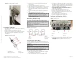
FIGURE 2 Connecting the Power Supply Unit
1. Grommets
3. Mount the power supply unit on the rear side of the AP bracket and
fasten the power supply to the bracket with the M4 screws and
torque to 2.259 N.m (20 in-lbs).
4. Mount AP bracket to the AP.
a. Place the rear side of the AP on the front side of the AP
mounting bracket so that the four larger screw holes on the
bracket align with the four screw holes on the AP.
b. Use four 0.250-28 x 0.5-inch hex bolts with split lock and flat
washer sets to mount the AP bracket to the AP. Tighten the bolts
to 3.0 N.m (27 in-lbs).
CAUTION! Make sure that the screws are no longer than 0.5
inch. If a screw is longer than 0.5 inch, it can damage the AP
chassis.
FIGURE 3 Attaching the AP to the Mounting Bracket
1. DC Power
2. AC Power
3. Screws
5. Connect the DC wire to the AP with cable gland.
NOTE: Cable gland use is mandatory, and the DC wires must first
be inserted into the cable gland before making the connection to
the unit. Otherwise, you will need to disconnect again to install the
cable gland.
Refer to
on page 2.
Copyright
©
2020 CommScope, Inc. All rights reserved.
Page 1 of 5
Published September 2020, Part Number 800-72458-001 Rev A
Times
tamp: 2020 Oct
ober 7 6:04 | Codes
tamp: 2020 Ma
y 08 11:00 UT
C (O
T: 2.5.4)—c
ommsc
ope log
o o
verride added


