860452168
Issue 7, April 2014
www.commscope.com
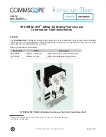
SYSTIMAX 360
™
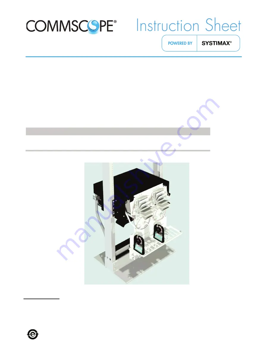
360G2 4U Sliding Front Access
Combination Shelf Instructions
© 2014 CommScope, Inc. All rights reserved
Page 1 of 21
General
The
SYSTIMAX
360
™
360G2 4U sliding, front access fiber optic combination shelf mounts onto a standard
19-inch (483mm), 23-inch (584mm) or ETSI equipment rack. This product is intended for indoor use or may be
used outdoors in a suitable protective enclosure.
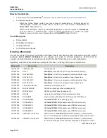
Ordering information is listed below:
Material ID
Part No.
Description
760193896
360G2-4U-MOD-SD
360G2 4U sliding modular cassette shelf
760101089
360G2-4U IP-SD
360G2 4U sliding adapter panel shelf
SYSTIMAX 360
™
360G2 4U Sliding, Front Access Fiber Optic Combination Shelf
This product is covered by one or more of the following U.S. patents or their foreign equivalents:
7,113,667 B2, 7,200,314 B2


