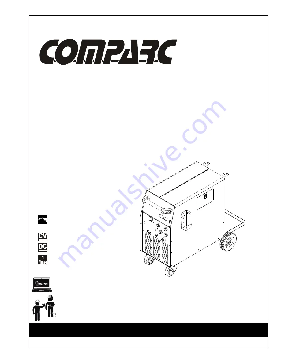
Comparc MM 300-ES, Owner'S Manual
The Comparc MM 300-ES user manual is an essential resource for owners of this exceptional product. Designed to provide detailed instructions and insightful tips, our comprehensive owner's manual ensures users can maximize the potential of their MM 300-ES. Download this manual for free from our website 88.208.23.73:8080 and start enjoying the full benefits of this exceptional product.
Share
Download


Reviews:
No comments
Related manuals for MM 300-ES
W64-1
Brand: WIA Pages: 28
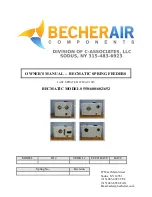
BECMATIC 550
Brand: BecherAir Components Pages: 17

AKM 96RM-E
Brand: janitza Pages: 76
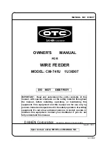
OTC CM-741U
Brand: Daihen Pages: 34

Dillon Conversion Kit
Brand: RCBS Pages: 12
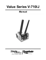
Streamfeeder Value Series
Brand: Barry-Wehmiller Pages: 58
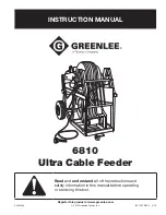
Greenlee 6810
Brand: Textron Pages: 26
VR 2000
Brand: Fronius Pages: 42
ABIDRIVE V2
Brand: Abicor Binzel Pages: 136
Stripmaster 950
Brand: IDEAL Pages: 16
GEK-106273L
Brand: GE Pages: 209

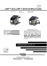
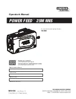
Power Feed 10 Robotic K1780-2
Brand: Lincoln Electric Pages: 28
76202
Brand: Lincoln Electric Pages: 13
K2536-6
Brand: Lincoln Electric Pages: 59
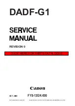
DADF-G1
Brand: Canon Pages: 154
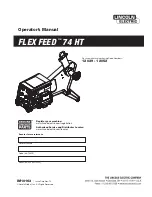
FLEX FEED 74 HT
Brand: Lincoln Electric Pages: 59
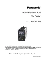
YW-50DNW
Brand: Panasonic Pages: 20
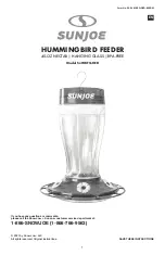
SJ-WBFG-RED
Brand: sunjoe Pages: 20


