background image


Computer Automation Technology, Inc


7378 W. Atlantic Blvd. #239 
Margate, Florida 33063 
Phone: (954) 978-6171  Fax: (561) 488-2894 
Internet: 

http://www.catauto.com


CAT-250 

Repeater Controller 

Summary of Contents for CAT-250

Page 1: ...Computer Automation Technology Inc 7378 W Atlantic Blvd 239 Margate Florida 33063 Phone 954 978 6171 Fax 561 488 2894 Internet http www catauto com CAT 250 Repeater Controller ...

Page 2: ...ntrol Definitions 3 5 Zone 3 DTMF Control Definitions 3 6 Zone 4 DTMF Control Definitions 3 7 Zone 5 DTMF Control Definitions 3 8 Zone 6 DTMF Control Definitions 3 9 Zone 7 DTMF Control Definitions 3 9 Zone 8 DTMF Control Definitions 3 10 Chapter 4 Repeater Operation Features Time of Day Message 4 1 DTMF Keypad Test 4 1 DTMF Access 4 1 Forced DTMF Entry 4 1 DTMF Muting Override 4 1 Repeater ID AT ...

Page 3: ...OR Logic 6 1 Connection to Repeater s Receiver 6 1 Connecting to Repeater s Transmitter 6 1 Connecting to CTCSS Decoder 6 1 Interface Review 6 1 Connector Kit 6 2 Power Supply 6 2 Audio De emphasis 6 2 Audio Level Adjustment 6 2 Printed Circuit Board Layout 6 2 Connector Assignment Table J2 6 3 Connector Assignment Table J1 6 4 TS 64 CTCSS Wiring Diagram 6 4 Chapter 7 RS 232 Computer Interface ISP...

Page 4: ...advanced 20 position scheduler fully automates repeater operation Any command that can be manually executed can also be scheduled to one minute accuracy Program the hours minutes day of week or day of month and month of year The CAT 250 will do the rest Courtesy Tone Separate courtesy tones denote repeater and link activity Create up to eight custom courtesy tones and assign their use by executing...

Page 5: ...2D Voice Vocabulary 290 Words DTMF Receivers 2 MT8870 Operating Temperature 15 to 55 degrees C Call Letter ID 4 Buffer size VOICE 15 CW 16 User Function Outputs 6 Switch 40VDC 50mA Logic Inputs 4 10K ohm input impedance Low 0 to 0 8VDC High 2 4 to 15VDC Logic Outputs Open Collector Relay Driver 28VDC at 50mA Audio Input Receiver 0 2 2VAC adjustable 10K ohms Audio Output Transmitter 2VAC adjustable...

Page 6: ... Pin D connector to be compatible with other CAT controllers CAT 250 CAT 250 REPEATER AND TRANSCEIVER CONFIGURATION J2 6 J2 4 J2 25 J2 10 J2 11 J2 13 J2 1 COR 1 CTCSS 1 PTT 1 TX AUDIO 1 RX AUDIO 1 GROUND USER INPUT 3 USER INPUT 4 USER INPUT 1 USER INPUT 2 J2 22 J2 21 J2 2 J2 15 J2 14 USER OUTPUT 3 USER OUTPUT 2 USER OUTPUT 1 J2 19 J2 20 USER OUTPUT 4 J2 17 J2 16 GROUND 12VDC OUTPUT J1 1 J1 4 J1 3 ...

Page 7: ...SS 2 J4 15 J4 14 J4 17 J4 22 J4 18 J4 13 J4 2 J4 1 J4 16 PORT 3 CONTROL REPEATER COR CTCSS OUT REPEATER PTT RX AUDIO 12VDC INPUT GROUND PORT 1 CONTROL PORT 2 CONTROL COR 1 CTCSS 1 PTT 1 TX AUDIO 1 RX AUDIO 1 GROUND USER INPUT 3 USER INPUT 4 USER INPUT 1 USER INPUT 2 REPEATER CAT 250 RLS 1000 THREE TRANSCEIVERS J2 15 J2 14 J2 20 USER OUTPUT 3 USER OUTPUT 2 USER OUTPUT 1 USER OUTPUT 4 J2 19 J2 8 USE...

Page 8: ...e a PTT signal to key the transmitter CAT 250 J2 6 J2 4 J2 25 J2 10 J2 11 J2 13 COR 1 CTCSS 1 PTT 1 TX AUDIO 1 RX AUDIO 1 GROUND J2 16 J2 17 12VDC OUTPUT GROUND J2 1 USER INPUT 3 USER INPUT 4 USER INPUT 1 USER INPUT 2 J2 22 J2 21 J2 2 J1 1 J1 4 J1 3 J1 2 COR 2 TX AUDIO 2 PTT 2 CTCSS 2 RX AUDIO 2 J1 5 J2 15 J2 14 USER OUTPUT 3 USER OUTPUT 2 USER OUTPUT 1 J2 19 J2 20 USER OUTPUT 4 REPEATER TRANSCEIV...

Page 9: ... COR 1 CTCSS 1 PTT 1 TX AUDIO 1 RX AUDIO 1 GROUND WX 250 J2 16 J2 17 12VDC OUTPUT GROUND REPEATER PTT OUTPUT PTT INPUT J4 3 J4 2 J4 11 J4 10 TX AUDIO OUTPUT TX AUDIO INPUT J4 4 WX ALERT DISABLE WX ALERT ENABLE J4 9 J4 1 PTT GROUND J4 7 J4 6 WX ALERT START WX ALERT STOP J4 8 GROUND J2 8 USER OUTPUT 6 CAT 250 WX 250 AUXILIARY RECEIVER CONFIGURATION J1 1 J1 4 J1 3 J1 2 COR 2 TX AUDIO 2 PTT 2 CTCSS 2 ...

Page 10: ...USER INPUT 4 USER INPUT 1 USER INPUT 2 J2 22 J2 21 J2 2 J2 15 J2 14 USER OUTPUT 3 USER OUTPUT 2 USER OUTPUT 1 J2 19 J2 20 USER OUTPUT 4 J2 6 J2 4 J2 25 J2 10 J2 11 J2 13 J2 1 COR 1 CTCSS 1 PTT 1 TX AUDIO 1 RX AUDIO 1 GROUND USER INPUT 3 USER INPUT 4 USER INPUT 1 USER INPUT 2 J2 22 J2 21 J2 2 J2 15 J2 14 USER OUTPUT 3 USER OUTPUT 2 USER OUTPUT 1 J2 19 J2 20 USER OUTPUT 4 J1 1 J1 4 J2 17 J2 16 J1 3 ...

Page 11: ... 5 should be ON for duplex transceiver operation and OFF for simplex transceiver operation Switch 6 This switch places the CAT 250 in the cross band repeat mode With transceivers on both Port 1 and Port 2 enabled the link with the 5001 command A signal received by the Port 1 receiver will only key the Port 2 transmitter and a signal received by the Port 2 receiver will only key the Port 1 transmit...

Page 12: ...change the status of a channel key up and send the control operator code 100 followed by the zone number channel number and a 1 to turn the channel ON or a 0 to turn the channel OFF Un key and the voice will read back the zone channel number and control activity The voice will say ONE ONE ON or THREE FIVE OFF Example With a control operator prefix of 100 turn Zone 2 Channel 1 ON Un key and the voi...

Page 13: ...R CTCSS ENABLE 4 PORT 2 TURN ON DELAY ENABLE 5 PORT 2 DTMF PAD TEST ENABLE 6 PORT 2 AUTO DISCONNECT ENABLE 7 PORT 2 DTMF MUTING ENABLE 8 PORT 2 TIMEOUT ENABLE 1 PORT 2 CONTROL OPERATOR ENABLE 2 PORT 2 MACRO CONTROL ENABLE 3 RESERVED ENABLE 4 RESERVED ENABLE 5 RESERVED ENABLE 6 RESERVED ENABLE 7 RESERVED ENABLE 8 RESERVED ENABLE 1 USER LOGIC INPUT 1 ENABLE 2 USER LOGIC INPUT 2 ENABLE 3 USER LOGIC I...

Page 14: ...E 1 REPEATER ID 1 At Rest ENABLE 2 REPEATER ID 2 Active ENABLE 3 SQUELCH TAIL MESSAGE ENABLE 4 TRANSMITTER DROP MESSAGE ENABLE 5 TIMED MESSAGE 1 ENABLE 6 TIMED MESSAGE 2 ENABLE 7 RESERVED ENABLE 8 RESERVED ENABLE 1 FAN CONTROL ENABLE 2 CTCSS ENCODER LOGIC ENABLE 3 ECHOLINK CONTROL ENABLE 4 TRANSMITTER HANG TIME ENABLE 5 RESERVED ENABLE 6 RESERVED ENABLE 7 RESERVED ENABLE 8 RESERVED ENABLE 1 RESERV...

Page 15: ...channel is useful during periods when noise bursts are present on the repeater input 5 Port 1 DTMF Pad Test Enable When this channel is enabled a repeater user is able to perform a test of their radio s 12 or 16 button keypad through the repeater port As the numbers are being decoded they are stored in memory When the repeater user stops transmitting the controller will read back all the numbers t...

Page 16: ... before the controller will activate the repeater A time delay of 0 1 to 9 9 seconds can be selected with the 624 programming command When the CAT 250 is initialized this timer defaults to 1 0 seconds This channel is useful during periods when noise bursts are present on the transceiver input 5 Port 2 DTMF Pad Test Enable When this channel is enabled a repeater user is able to perform a test of th...

Page 17: ...ble DTMF muting precede the DTMF string with a 8 Port 2 Timeout Enable Link time out is user programmable with the 602 timer programming commands When the CAT 250 is initialized this timer defaults to 3 minutes When this channel is turned off the repeater link port will not timeout 1 Port 2 Control Operator Enable When this channel is enabled the CAT 250 will accept control operator commands to ch...

Page 18: ...y net operations when it is not desirable to have channels change automatically To suspend scheduler operation turn this channel off 6 Time of Day Request Enable When this channel is enabled repeater users can request a time of day announcement by entering the time of day request number This message will consist of up to 15 words selected from the voice vocabulary table and is programmed with the ...

Page 19: ...s turned on Connector J2 pin 7 will sink 50 MA to ground 6 USER Output Switch 6 Enable When this channel is enabled switch 4 is turned on Connector J2 pin 8 will sink 50 MA to ground 7 DTMF Access Enable When this channel is enabled a DTMF Access number selected by programming command 503 must be entered to activate Port 1 The repeater will continue to operate until a period of inactivity occurs d...

Page 20: ...f This message will repeat subject to the setting of the 611 drop out message timer This message will consist of up to 15 words selected from the voice vocabulary table and is programmed with the 3104 command 5 Timed Message 1 Enabled When this channel is enabled the timed voice message will occur on a regular schedule subject to the setting of the timed message timer This message will consist of ...

Page 21: ...MF Muting Zone 1 Channel 7 is enabled a DTMF command entered through Port 1 will be muted on both the Port 1 and Port 2 transmit audios When this channel is enabled Port 2 transmit audio will be the actual DTMF command The DTMF command will continue to be muted on the Port 1 transmit audio 4 Transmitter Hang Time Enable When this channel is enabled the transmitter will have a hang time subject to ...

Page 22: ... the repeater to DTMF access mode by re entering 325 the DTMF access code The voice will say OK DOWN Forced DTMF Command Entry Port 1 and Port 2 During normal operation a DTMF command is entered when the port goes inactive It is possible to force a DTMF command entry even while the port is active The CAT 250 will accept the D key as an entry command This key can be changed with the 29X programming...

Page 23: ... link connect control Macro 27 number 5001 The CAT 250 will connect the link port to the repeater port and the voice will say LINK ON See the Event Macro Data table in Chapter 5 Link Receive Only Key up on the repeater s input and enter the link receive only control Macro 26 number 5002 The CAT 250 will connect the link port to the repeater port and the voice will say LINK RECEIVER ON The link tra...

Page 24: ...am the Master UNLOCK number set dipswitch 8 to the on position The voice will say ENTER CONTROL Key up and enter a seven digit number Un key if the number is accepted the voice will say CONTROL OK If the number is rejected the voice will say ENTER CONTROL Key up and enter the seven digit number Set dipswitch 8 to the off position Unlocking the Controller By Radio From Port 1 and Port 2 7654321 To ...

Page 25: ...TONE PORT 2 37XX 01 08 PLAY COURTESY TONE PORT 1 3800 PLAY COURTESY TONE PORT 2 3900 PULSE USER OUTPUT SWITCH 1 PULSE RATE 100mSEC 41XX 01 99 PULSE USER OUTPUT SWITCH 2 PULSE RATE 100mSEC 42XX 01 99 PULSE USER OUTPUT SWITCH 3 PULSE RATE 100mSEC 43XX 01 99 PULSE USER OUTPUT SWITCH 4 PULSE RATE 100mSEC 44XX 01 99 PULSE USER OUTPUT SWITCH 5 PULSE RATE 100mSEC 45XX 01 99 PULSE USER OUTPUT SWITCH 6 PUL...

Page 26: ...PUT PULSE 500mSEC 625X 0 OFF 1 ON 2 PULSE USER FUNCTION SWITCH 6 OUTPUT PULSE 500mSEC 626X 0 OFF 1 ON 2 PULSE DISCONNECT PORT 2 FROM PORT 1 7000 CONNECT PORT 2 TO PORT 1 7001 CONNECT PORT 2 RECEIVER TO PORT 1 7002 DTMF ACCESS REPEATER 710X 0 OFF 1 ON DISABLE EVENT MACRO 80XX 01 50 ENABLE EVENT MACRO 81XX 01 50 DISABLE USER MACRO 82XX 01 40 ENABLE USER MACRO 83XX 01 40 SEND VOICE WORD 9XXX 001 998 ...

Page 27: ...cations 01 40 Key up and send 13XX Un key and voice will read back the macro control number followed by the enable control byte followed by the macro data commands stored at that memory location If the location is empty the voice will say MACRO NUMBER XX NO CODE NO DATA Program User Macro Locations 01 40 Key up and send 14XX followed by the macro control number and the string of internal commands ...

Page 28: ...1 SCHEDULED EVENT MACRO 31 07 LOGIC INPUT 2 ACTIVE HIGH 32 SCHEDULED EVENT MACRO 32 08 LOGIC INPUT 2 ACTIVE LOW 33 SCHEDULED EVENT MACRO 33 09 LOGIC INPUT 3 ACTIVE HIGH 34 SCHEDULED EVENT MACRO 34 10 LOGIC INPUT 3 ACTIVE LOW 35 SCHEDULED EVENT MACRO 35 11 LOGIC INPUT 4 ACTIVE HIGH 36 SCHEDULED EVENT MACRO 36 12 LOGIC INPUT 4 ACTIVE LOW 37 SCHEDULED EVENT MACRO 37 13 PLAY COURTESY TONE 1 38 SCHEDUL...

Page 29: ...CSS INACTIVE 03 PORT 2 COR CTCSS ACTIVE 04 PORT 2 COR CTCSS INACTIVE 05 LOGIC INPUT 1 ACTIVE HIGH 1511 06 LOGIC INPUT 1 ACTIVE LOW 1510 07 LOGIC INPUT 2 ACTIVE HIGH 1521 08 LOGIC INPUT 2 ACTIVE LOW 1520 09 LOGIC INPUT 3 ACTIVE HIGH 1531 10 LOGIC INPUT 3 ACTIVE LOW 1530 11 LOGIC INPUT 4 ACTIVE HIGH 1541 12 LOGIC INPUT 4 ACTIVE LOW 1540 13 COURTESY TONE PORT 1 INPUT 5301 3800 5300 14 COURTESY TONE P...

Page 30: ... 43 44 SCHEDULED MACRO 44 45 SCHEDULED MACRO 45 46 SCHEDULED MACRO 46 47 SCHEDULED MACRO 47 48 SCHEDULED MACRO 48 49 SCHEDULER MACRO 49 50 POWER UP 6141 9275 9002 9050 9999 6001 9101 9100 6140 Check Time of Day Key up and send 20 Un key the voice will read the time day of week day of month month and year Example THE TIME IS TWELVE FIFTEEN PM MONDAY MONTH THREE DAY OF MONTH TWENTY THREE YR THREE NO...

Page 31: ... programming command To change this key to key up and send 29 Un key the voice will say CONTROL OK Select A B C or D To read the command key up and send 29 Send Voice Message 3001 3020 Key up and send 3001 Un key and the voice synthesizer will say the ID Program Voice Message 3101 3120 Key up and send 31XX followed by the message number and three digit numbers that represent the words required to ...

Page 32: ...SE OFF 12 REMOTE BASE ON REMOTE BASE ON 13 REMOTE BASE RECEIVE ONLY REMOTE BASE RECEIVE 14 REMOTE BASE AUTO CLEAR REMOTE BASE CLEAR 15 MESSAGE 15 MESSAGE 15 16 MESSAGE 16 MESSAGE 16 17 MESSAGE 17 MESSAGE 17 18 MESSAGE 18 MESSAGE 18 19 MESSAGE 19 MESSAGE 19 20 MESSAGE 20 MESSAGE 20 Erase Synthesized Voice Message 3201 3220 Key up and send 32XX Un key and the voice will say CONTROL OK The voice ID w...

Page 33: ... repeater user keys up during a voice ID the voice ID will stop Control Code And Prefix Number Memory This memory area is reserved for storage of control and prefix numbers These numbers can be from one to seven digits and will change to a default value when the CAT 250 is powered up with dip switch 7 set to the on position Control Operator Prefix Number Port 1 Repeater 501 This programming comman...

Page 34: ...d 505 5000 Un key and the voice will say CONTROL OK Port 2 Link Connect Control Number 506 This number is used to connect the link Example To program a link connect control number of 5001 key up and send 506 5001 Un key and the voice will say CONTROL OK Port 2 Link Receive Only Control Number 507 This number is used to activate the link receive only mode Example To program a link receive only cont...

Page 35: ...t is clear before generating a voice ID If the System ID Timer expires and the input is still not clear the CAT 250 will wait an additional period of time before a forced ID is sent This timer sets the length of this period This timer is programmable between 60 and 1799 seconds The timer default is 120 seconds CRT and Programming Length Timer 605 During the programming mode this timer determines t...

Page 36: ...he time between loss of COR and the generation of the courtesy beep This timer is programmable between 0 1 and 9 9 seconds When initialize this timer defaults to 1 second Example To program the timer for 2 5 seconds key up and enter 621 25 Courtesy Beep to PTT Drop Timer 622 This timer determines the time between the generation of the courtesy beep and the time the repeater transmitter turns off T...

Page 37: ...tone X represents the courtesy tone table location Program Courtesy Tone 1 8 Key up and send 92X followed by the frequency duration and separation numbers from the courtesy tone table This programming command is used to develop eight custom courtesy tones 151 through 158 The tone created with the 925 programming command is identified as tone 155 Example Program courtesy tone table location 5 with ...

Page 38: ...EXIT If you fail to exit the programming mode the CAT 250 will exit the programming mode when the 605 timer expires The CAT 250 will return to normal operation The voice will say TIMER EXIT Tone 1 Frequency 440Hz Table Position Tone 1 Duration 100msec Programming Command Time 1 Separation 50msec 92 1 14 2 1 21 3 2 26 4 Tone 2 Frequency 660Hz Tone 3 Duration 200msec Tone 2 Duration 150msec Tone 3 F...

Page 39: ...RT TIME OF DAY Hours and Minutes only 29 READ FORCED ENTRY KEY 29X PROGRAM FORCED ENTRY KEY D 30XX PLAY VOICE MESSAGE 1 20 31XX PROGRAM VOICE MESSAGE 1 20 32XX ERASE VOICE MESSAGE 1 20 33 SEND CW IDENTIFICATION 34 PROGRAM CW IDENTIFICATION 35 ERASE CW IDENTIFICATION 36XX SET CW TONE FREQUENCY 01 32 25 37X SET CW SPEED 1 5 1 10 2 15 3 20 4 25 5 30WPM 3 38XX SET MUTING TONE FREQUENCY 01 32 20 501 PR...

Page 40: ...09 TIMED MESSAGE 2 TIMER 60 1799 SECONDS 1799 610 SQUELCH TAIL MESSAGE TIMER 60 1799 SECONDS 1799 611 DROP OUT MESSAGE TIMER 60 1799 SECONDS 1799 612 FAN CONTROL TIMER 60 621 COR DROP TO COURTESY BEEP TIMER 0 1 9 9 SECONDS 1 0 622 COURTESY BEEP TO PTT DROP TIMER 0 1 9 9 SECONDS 4 0 623 PRE VOICE DELAY TIMER 0 1 9 9 SECONDS 0 5 624 TURN ON DELAY TIMER 0 1 9 9 SECONDS 1 0 625 DTMF MUTING TIMER 0 1 9...

Page 41: ...J2 13 and the COR to J2 6 of the CAT 250 Verify this line changes from less than 0 8VDC to greater than 3 0 VDC If the COR line will not meet these limits it may be necessary to add a pull up resistor to the COR 1 line This may also be true for the COR 2 input Space is provided on the CAT 250 board to add pull up resistors Connection to Transmitter Locate your repeater s Push To Talk input When gr...

Page 42: ...dback resistors of the receiver audio amplifiers This will lower the gain at the higher frequencies and produce the necessary de emphasis If de emphasize audio is supplied to the controller these jumpers should be removed Audio Level Adjustment The audio mixing switching circuits of the CAT 250 are optimized around an input and output of 10dBM 220mV Connect a signal generator to the repeater s rec...

Page 43: ... sensitive and you find the TX2 Audio level control is near minimum set the jumper plug at J5 between pins 1 and 2 Compare the receive and synthesized voice audio and adjust the voice Level R30 as desired The synthesized voice should be slightly lower than the receive audio Unlock the CAT 250 by keying up on the repeater input and entering 1234567 Key up and enter the 901 test tone programming com...

Page 44: ...equency CTCSS tone content GROUND TS 64WDS RED BLUE ORANGE WHITE VIOLET GREEN WHITE BLACK YELLOW GREEN YELLOW BLACK 12VDC CAT 250 J2 4 DISCRIMINATOR TRANSMITTER EXCITER CAT 250 RX1 INPUT J2 13 2200 OHM PULL UP RESISTOR HIGH PASS OUT HANG UP PTT INPUT GROUND CTCSS TONE OUT DISCRIMINATOR PTT OUTPUT RX AUDIO MUTE 12VDC BLUE WHITE 11 2 10 12 1 6 9 8 13 3 DISCRIMINATOR GROUND HIGH PASS FILTER IN 1 TRAN...

Page 45: ... to upload the latest firmware version of the CAT 250 controller available at the www catauto com web site Under RESOURCES select FIRMWARE UPDATES and then CAT 250 and the latest version Follow the procedure described in the CAT 250 Firmware Download Instructions Start the ISP Loader program to display the ISP Loader For CAT 250 window Follow the directions described in the window ...

Page 46: ...tor window Activation Of The RS 232 Port With Dipswitch 8 To activate the RS 232 port set the DC power to OFF Set dipswitch 8 to ON Turn the DC power to ON Activation Of The RS 232 Port By Radio To activate the RS 232 port key up into Port 1 and enter the control operator prefix code 100 followed by 97 The voice synthesizer will say CONNECT and the transmitter will drop ...

Page 47: ...296 D 310 Danger 311 Data 312 Date 313 Day 314 Days 315 Decrease 317 Delay 319 Delta 320 Direction 322 Do 323 Down 324 E 340 Echo 342 Ed suffix 343 Emergency 344 End 345 Enter 346 Error 348 Exit 350 F 370 Failure 372 Fast 374 Feet 376 For 004 Foxtrot 386 Frequency 388 Friday 389 From 390 Full 392 G 410 Get 412 Go 413 Golf 414 Good 415 H 440 Ham 443 Hamfest 444 Have 445 Hertz 449 High 450 Hotel 453...

Page 48: ...2 T 820 Tango 821 Temperature 824 Test 826 Than 827 Thank You 828 That 829 The shortE 830 The longE 831 Then 832 This 833 This is 834 Thunderstorms 836 Thursday 837 Time 838 Timer 839 To 002 Today 840 Tomorrow 841 Tone 854 Tonight 842 Tornado 843 Traffic 845 Transceiver 853 Transmit 846 Try 848 Tuesday 849 Turn 850 U 870 Uniform871 Unit 872 Until 874 Up 875 Use noun 876 Use verb 877 V 880 Victor 8...

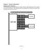
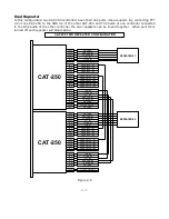
Page 49: ...9 1 Chapter 9 Drawings CAT 250 Repeater Controller Figure 9 1 ...

Page 50: ...10 1 Chapter 10 Schematic Controller Board CAT 250 Sheet 1 of 3 Controller Board CAT 250 Sheet 2 of 3 Controller Board CAT 250 Sheet 3 of 3 ...

Page 51: ...10 2 ...

Page 52: ...10 3 ...

Page 53: ...10 1 ...

Page 54: ... Power J3 1 Connector Header 1X3 J5 2 Connector Header 1X5 J6 J7 1 Crystal 3 58 MHz Y2 1 Fuse 0 5 Amp Fast F1 1 I C 25C640 U9 1 I C 89C668HBA U10 1 I C ATF1502ASL U8 1 I C LM340 05 U1 2 I C LM348 U6 U13 1 I C MAX335 U5 1 I C MAX232 U7 1 I C MCP101 U14 1 I C MSP53C391 U2 2 I C MT8870D U3 U11 1 I C TPIC6C595 U4 1 I C ULN2804 U12 3 Resistor 100 Ohm R14 R27 R28 2 Resistor 620 Ohm R12 R13 2 Resistor 5K...

Page 55: ...R32 R33 4 Resistor 100K R2 R3 R6 R7 2 Resistor 560K R4 R8 R11 2 Resistor User Option R10 R11 1 Resonator 12 MHz Y1 1 Switch DIP SW 8 SW1 1 Switch Push Button SW2 6 Test Points TP1 TP2 TP3 TP4 TP5 TP6 1 Transorb 1N6278A CR1 ...

Reviews: