background image


SBC Series 


Full Size 11-slots Chassis 

FA-UNIT-F11BE 

Full Size MicroATX Chassis 

FA-UNIT-F11ME 

User’s Manual 


CONTEC CO.,LTD.


Summary of Contents for FA-UNIT-F11BE

Page 1: ...SBC Series Full Size 11 slots Chassis FA UNIT F11BE Full Size MicroATX Chassis FA UNIT F11ME User s Manual CONTEC CO LTD ...

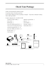
Page 2: ...ber pads 4 User s Manual 1 Screws for Rubber pads M4 x 8 6 Warranty Certificate 1 Screws used for expansion bay fixing Serial number label 1 and board installation M3 x 6 32 Screws for HDD 6 32UNC x 5 8 Hexagon spacer 13 Plastic Spacers 5 x 11 Slot cover Power cable x 6 Screws for Rubber pads Screws used for expansion bay fixing and board installation x 32 x 8 Screws for HDD x 13 Hexagon spacer Ch...

Page 3: ...XXXXXXXXX XXXXXXXXXXXXX Serial number label Warranty Certificate Copyright Copyright 2013 CONTEC CO LTD ALL RIGHTS RESERVED No part of this document may be copied or reproduced in any form by any means without prior written consent of CONTEC CO LTD CONTEC CO LTD makes no commitment to update or keep current the information contained in this document The information in this document is subject to c...

Page 4: ...in Service 3 Liability 3 Safety Precautions 4 Safety Information 4 Handling Precautions 5 Environment 6 Inspection 6 Storage 6 Disposal 6 2 NAME OF EACH PART AND DIMENSIONS DIAGRAM 7 Parts of the Chassis 7 Front Side View 7 Rear Side View 7 Dimensions 8 FA UNIT F11BE 8 FA UNIT F11ME 10 Positions of backplane or motherboard installation holes 12 3 INSTALLING THE MOTHERBOARD 13 Installing the backpl...

Page 5: ...ives 17 Preparation 17 Installing Disk Drives 17 Installing Removing a fan and filter 18 Installation conditions 19 Installing the wall mount bracket 20 4 CONNECTORS 21 Power Supply 21 Backplane or motherboard power supply connectors 21 HDD FDD power supply connectors 21 Switches and LEDs 22 USB Connector 23 5 SYSTEM REFERENCE 25 Specification 25 ...

Page 6: ... filter and cooling fan can be replaced externally These fans can easily be replaced externally without removing the top cover A chassis fixing bracket is attached as standard Configuration Backplanes and mother boards are sold separately You need prepare a CONTEC backplane corresponding to this product separately For more details of the corresponding backplanes see Option When using a third party...

Page 7: ... x 8 ISA x 1 BPC 1111 PCI Backplane with 10 Slots PCI x 10 Other FA CLAMP 01 Clamp for PCI ISA board 5 pcs Check the CONTEC s Web site for more information on these options Available Replaceable Parts for Maintenance POW300X 300W ATX Power Supply FAN1225S Fan 120 x 25 with Sensor FAN0825S Fan 80 x 25 with Sensor FLT121 Fan Filter 127 x 127 ...

Page 8: ...ge only when this device is returned freight prepaid with a copy of the original invoice and a Return Merchandise Authorization to the distributor or the CONTEC group office from which it was purchased This warranty is not applicable for scratches or normal wear but only for the electronic circuitry and original products The warranty is not applicable if the device has been tampered with or damage...

Page 9: ...icates a potentially hazardous situation which if not avoided may result in minor or moderate injury or in property damage FCC PART 15 Class A Notice This equipment has been tested and found to comply with the limits for a Class A digital device pursuant to part 15 of the FCC Rules These limits are designed to provide reasonable protection against harmful interference when the equipment is operate...

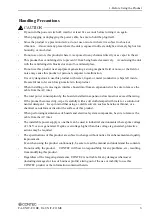
Page 10: ...n expansion slot be sure to remove the cable from the AC inlet The total power consumption by the boards installed in expansion slots must not exceed the rating If the product becomes dirty wipe it carefully with a soft cloth damped with water or a solution of neutral detergent Keep in mind that using a volatile solvent such as benzine or thinner or a chemical can deform or discolor the surface of...

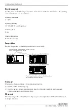
Page 11: ...entilating slits must neither be blocked nor have dust or foreign matters adhering Front side view Rear side view FA UNIT F11BE Rear side view FA UNIT F11ME Ventilating slits must neither be blocked nor have dust or foreign matters adhering RESET Storage When storing this product keep it in its original packing form 1 Put this product in the storage bag 2 Store the package at room temperature at a...

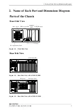
Page 12: ...ons Diagram Parts of the Chassis Front Side View USB port Fan replacement hatch Reset switch HDD access LED POWER LED POWER Switch RESET Figure 2 1 Front Side View Rear Side View Connector plate Figure 2 2 Rear Side View of FA UNIT F11BE Connector plate FAN cover Figure 2 3 Rear Side View of FA UNIT F11ME ...

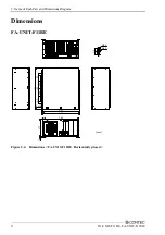
Page 13: ...Each Part and Dimensions Diagram 8 FA UNIT F11BE FA UNIT F11ME Dimensions FA UNIT F11BE 8 φ5 420 RESET 177 364 10 380 396 80 80 160 130 130 15 R4 5 R2 5 mm Figure 2 4 Dimensions FA UNIT F11BE Horizontally placed ...

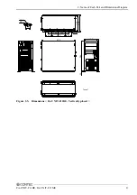
Page 14: ...2 Name of Each Part and Dimensions Diagram FA UNIT F11BE FA UNIT F11ME 9 RESET 8 φ5 177 420 364 10 193 209 80 80 160 130 130 mm 15 R2 5 R4 5 Figure 2 5 Dimensions FA UNIT F11BE Vertically placed ...

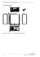
Page 15: ... of Each Part and Dimensions Diagram 10 FA UNIT F11BE FA UNIT F11ME FA UNIT F11ME RESET 8 φ5 177 420 364 10 380 396 80 80 160 130 130 16 15 R4 5 R2 5 mm Figure 2 6 Dimensions FA UNIT F11ME Horizontally placed ...

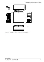
Page 16: ...2 Name of Each Part and Dimensions Diagram FA UNIT F11BE FA UNIT F11ME 11 RESET 8 φ5 177 420 364 16 10 193 209 80 80 160 130 130 mm 15 R2 5 R4 5 Figure 2 7 Dimensions FA UNIT F11ME Vertically placed ...

Page 17: ... 2 5 R 2 10 12 7 91 44 137 16 208 15 24 139 7 45 26 228 9 18 38 7 62 176 53 212 09 20 62 15 875 30 48 76 2 213 36 233 68 246 38 116 88 179 54 mm Max Max Figure 2 8 Positions of backplane installation holes If a backplane or motherboard whose shaded area is not cut off is installed then a 3 5 inch or 5 inch drive may not be installed properly depending on the height of the installed parts etc ...

Page 18: ... the backplane motherboard 1 Remove the screws fastening the top cover then remove the cover When loosening the screws use the appropriate type of screwdriver that fits the screw head 2 First remove the fall off prevention bar from the expansion board Next fix the attached hexagon spacers or plastic spacers to the holes in the main unit and place the backplane motherboard on it and fix it with scr...

Page 19: ...installed following the same procedures Preparation 1 Turn the power switch off 2 Pull the power plug of the unit from the wall outlet Insertion of expansion board 1 Remove the screws fastening the top cover then remove the cover When loosening the screws use the appropriate type of screwdriver that fits the screw head 2 Remove the fall off prevention bar from the expansion board ...

Page 20: ...oard follow the steps below in the reverse order of plugging it 1 Before starting removing the expansion board pull the power plug of the unit from the wall outlet 2 Following the same procedures as for insertion remove the bracket fixing screws of the slot from which you want to remove the board 3 Remove the board by pulling it at a right angle to the expansion slot 4 Use the screw to fasten the ...

Page 21: ...E FA UNIT F11ME Replacing the connector plate The supplied connector plate has holes for accepting connectors If necessary the supplied connector plate can be replaced with another plate of different shape Figure 3 1 Replacing the connector plate ...

Page 22: ... drives built in it Preparation 1 Turn the power switch off 2 Pull the power plug of the unit from the wall outlet Installing Disk Drives 1 Remove the screws fastening the top cover then remove the cover When loosening the screws use the appropriate type of screwdriver that fits the screw head 2 Remove the fall off prevention bar from the expansion board ...

Page 23: ...sis 4 Return the fall off prevention bar and cover to their original positions and fix them with screws Installing Removing a fan and filter You can install remove a fan and filter without removing the top cover Filter FAN Finger guard FAN cover Relay connector The installation of the fan is obtained in the reverse order of detaching Figure 3 2 Installing Removing a fan and filter ...

Page 24: ...ME 19 Installation conditions To prevent a temperature rise install this chassis at a distance of at least 50mm from obstacles such as walls 50 Front Side View Rear Side View mm 50 50 50 50 Front Side View Rear Side View Figure 3 3 Installation conditions ...

Page 25: ...ll mount bracket Installing the attached bracket enables wall mount The bracket can be installed in two ways Install the bracket using an appropriate method in accordance with the use environment Horizontally Placed Vertically Placed Figure 3 4 Installing the wall mount bracket ...

Page 26: ... motherboard power supply connectors It connects it with Backplane or the motherboard Pin No Function Pin No Function 1 3 3V 11 3 3V 2 3 3V 12 12V 3 COM 13 COM 4 5V 14 ON OFF 5 COM 15 COM 6 5V 16 COM 7 COM 17 COM 8 P G 18 5V 9 5VS 19 5V 10 12V 20 5V Figure 4 1 Backplane or motherboard power supply connectors HDD FDD power supply connectors 1 12V 2 GND 3 GND 4 5V YELLOW BLACK BLACK RED To HDD or CD...

Page 27: ...n when you turn the power on The second switch is the reset switch for rebooting the system The red LED HDD indicates the access status of the hard disk drive These switches and LEDs operate with their respective connector cables connected to the corresponding connectors on the SBC CPU board Yellow Black 4 Reset SW Black Red 3 HDD LED White Black 1 Power SW 2 Power LED Black Green Figure 4 3 Switc...

Page 28: ... connection connectors The USB connector operates when a cable is connected to the relevant connector on SBC CPU board with a USB internal connection connector Pin 2 Pin 4 Pin 6 Pin 8 Pin 10 Pin 1 Pin 3 Pin 5 Pin 7 Pin 9 VCC1 USBP1 USBP1 GND N C VCC2 USBP2 USBP2 GND CHASSIS GND Figure 4 4 USB Connector Cable ...

Page 29: ...4 Connectors 24 FA UNIT F11BE FA UNIT F11ME ...

Page 30: ...Backplane dimensions mm 246 4 W x 264 2 D Max For details see Figure 2 8 BPM 1111 BPI 1111 BPC 1111 None Installable motherboard dimensions mm None Micro ATX size 246 4 W x 264 2 D Max For details see Figure 2 8 Dimensions mm 364 W x 177 H x 420 D Excluding raised parts Weight About 11kg Excluding backplane motherboard drives etc Table 5 2 Power supply specifications Item Specification Power capac...

Page 31: ...o the figures do not necessarily represent the tolerances for every operating condition Dimensions of installable board Max 340 5 220 0 L 122 0 H mm is a alf size case CAUTION The internal power supply and cooling fan fan filter are consumables requiring replacement after use for a certain period of time Although the standards are given below their lives may be shortened depending on the operating...

Page 32: ...ku Osaka 555 0025 Japan Japanese http www contec co jp English http www contec com Chinese http www contec com cn No part of this document may be copied or reproduced in any form by any means without prior written consent of CONTEC CO LTD 02152013 09012005 Management No A 51 066 02152013_rev6 Parts No LYFB624 ...

Reviews: