background image

1

Form No. 256827   Rev. 11/08

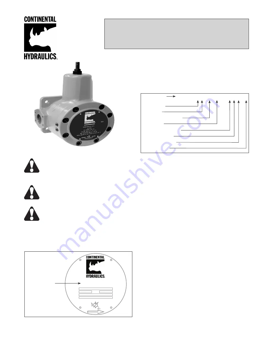
SERVICE MANUAL

PVR50 Flanged Series Pump

Installation, Startup, Operating Instructions, Parts Pages, Repair Procedures

“L” Design Series

Basic Pump

Pump Size
Pressure
Rotation & Mounting
Seal Type
Mechanical Options 
Control Options 
Integral Operator  


Design Letter

PVR50 - _ _ - _ - _ - 5  _ _ _ - L

Figure 1

Figure 2

PVR50-

RATINGS

S.U.S 200-250 @  100°F./C.S.T. 21-30 @  49°C.

r

rpm

v

IN

3

/r

p

psi

p

bar

m

l

/r

Model Code

50B15-RF-0-521-L


CAUTION


-

 Before performing any service  

  operation on any pump, be sure that all  

  pressure has been relieved from BOTH  

  SIDES of the system.


CAUTION


-

 Before performing any service  

  operation on any pump, disconnect or lock  

  off power supply.

  CAUTION -

 Before starting pump, be sure  

  that any resulting machine function will not  

  endanger persons or equipment.

PRODUCT IDENTIFICATION

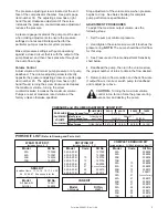
Each pump has an Ordering Code stamped on its 

nameplate.  See Figure 1 for the location of the 

Ordering Code.

This service manual applies to products with Ordering 

Codes like the sample in Figure 2.

INSTALLATION

PUMP DRIVE AND MOUNTING

When mounting the pump and motor, care must be 

taken to align the pump and motor shafts within .003 

T.I.R.  Direct inline through a jaw type/flexible web 

coupling is recommended for all Continental pumps.  

Tire-type flexing elements and chain-type drives are 

not recommended.  With belt drives, please consult 

factory.

To avoid axial and radial end loading of the pump 

shaft, do not couple the pump and motor shafts 

rigidly.  Allow freedom at the coupling for the two 

shafts to ride independently.

To prevent end loading, the space between the pump 

and motor shaft ends should be 3/4 inch (19.1 mm) 

for PVR50 pumps, or as the coupling manufacturer 

specifies.

PIPING AND RESERVOIR

The pump should be mounted with a minimum 

number of elbows or fittings.  The pump suction 

should be at least two (2) inch (50.8 mm) tube/pipe 

for PVR50 pumps and 2-1/2 inch (63.5 mm) tube/pipe 

for PVR50-70B pumps.

Summary of Contents for PVR50 Flanged Series

Page 1: ...nameplate See Figure 1 for the location of the Ordering Code This service manual applies to products with Ordering Codes like the sample in Figure 2 INSTALLATION PUMP DRIVE AND MOUNTING When mounting the pump and motor care must be taken to align the pump and motor shafts within 003 T I R Direct inline through a jaw type flexible web coupling is recommended for all Continental pumps Tire type flex...

Page 2: ...corresponding to the case drain in the pump or manifold If connected to a heat exchanger the case drain line should be protected with a 10 psi 7 bar maximum relief valve in parallel with the heat exchanger No other return lines should be connected in common with the case drain return 5 Rotate pump and motor by hand to insure free rotation 6 Set the machine controls to open the circuit and allow fr...

Page 3: ...low for this step 3 See Pressure and Volume Adjustment Sensitivity chart below 4 Deadhead the pump then turn the volume screw the proper number of turns to obtain the flow desired 5 Return pump to flow condition and check flow rate If output flow is incorrect switch pump to deadhead and readjust per above CAUTION Turning the maximum volume control in too far can force the pressure ring over center...

Page 4: ...ns Mechanical Options PVR50 PARTS DRAWINGS 14 12 358 7 22 88 89 66 67 56 57 58 24 2 3 Code LF Only INTERNAL SPLINE 66 67 86 or 87 2 3 Code 21 Tandem Pump Mounting 9 Tooth Spline A Mounting Code 22 Tandem Pump Mounting 13 Tooth Spline B Mounting Code 23 Tandem Pump Mounting 14 Tooth Spline C Mounting Code 31 Tandem Pump Mounting 13 Tooth Spline A Mounting Code 13 Double End Drive Shaft Code LF Left...

Page 5: ...ip Seal 2 25 153111 O Ring 1 25 Viton 162100 O Ring 1 26 70B 123328 Pipe Plug 2 27 250368 Thrust Screw Plug 1 29 256486 Volume Adj Screw Ass y 1 ITEM CODE PART DESCRIPTION QTY NO NO REQ D 30 250240 Pressure Adj Screw Ass y 1 31 8 9 256509 O Ring Union 1 32 8 9 256508 Flow Control Valve 1 33 2400 24 2500 350945 PMA 24B A 1 25 34 18 24 25 256510 Flare Connector 2 37 24 256889 Hydraulic Hose 20 1 39 ...

Page 6: ...ral Valve 32A 42A and 50B Only Code 25 Dual Pressure Volume Control With Integral Valve Code 8 Rate Control Valve for Dual Pressure Code 9 Rate Control Valve for Dual Volume PVR50 PARTS DRAWINGS Control Options 9 40 238 8 MAX 21 31 541 3 MAX VOLUME RATE CONTROL VALVE CODE 9 ONLY 37 33 50 83 84 34 34 23 90 607 1 MAX 37 33 50 83 84 34 53 34 52 51 48 14 50 368 3 MAX PRESSURE RATE CONTROL VALVE CODE 8...

Page 7: ...he housing should be pressed out from the front The cover bearing should be pulled out using an expanding type puller The bearings should not be reused once they have been removed 11 It is unlikely that further disassembly will be necessary in order to perform routine maintenance on the pump REASSEMBLY PROCEDURE 1 Clean and inspect parts to determine which parts are worn enough to require replacem...

Page 8: ...e bore in the thrust plate is concentric to the bearing bore in the cover If the bores are not concentric the thrust plate must be rotated 180 on the locating pins 11 Assemble the cover 2 and thrust plate 5 onto the housing 1 and align the bolt holes Rotate the shaft as the cover bolts 18 are tightened to assure that the vanes are not cocked 12 Torque the cover bolts to 100 lbs ft The shaft should...

Reviews: