pag. 1 / 4
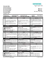
MANUALE ISTRUZIONI / INSTRUCTION MANUAL
IM260-IU v0.8
ELR-D2-V
ELR-D2-V
Relè differenziale di terra
Earth leakage relay
ATTENZIONE!!!
•
Leggere attentamente il manuale prima dell’utilizzo e l’installazione.
•
Questi strumenti devono essere installati da personale qualificato, nel
rispetto delle vigenti normative impiantistiche, allo scopo di evitare danni a
persone o cose.
•
Prima di qualsiasi intervento sullo strumento, togliere tensione dagli ingressi
di alimentazione e dalle uscite relè dove presenti.
•
Il costruttore non si assume responsabilità in merito alla sicurezza elettrica
in caso di utilizzo improprio del dispositivo.
•
I prodotti descritti in questo documento sono suscettibili in qualsiasi
momento di evoluzioni o di modifiche
WARNING!
•
Carefully read the manual before the installation or use.
•
This device is to be installed by qualified personnel, complying to current
standards, to avoid damages.
•
Before any maintenance operation on the device, remove supply inputs.
•
The manufacturer cannot be held responsible for electrical safety in case of
improper use of the equipment.
•
Products illustrated herein are subject to alteration and changes without
prior notice.
Descrizione
•
Relè differenziale di terra tipo A
•
Misure in vero valore efficace (TRMS)
•
Esecuzione modulare, 2 moduli per guida DIN
•
LED verde di segnalazione alimentazione (ON)
•
Toroide esterno
•
Funzionamento con sicurezza positiva impostabile
•
Visualizzazione della corrente differenziale
•
Display LCD retroilluminato
•
Pulsanti TEST e RESET sul fronte
•
Interfaccia di comunicazione RS485 integrata (Modbus RTU)
Description
•
Earth leakage relay type A
•
True RMS
•
Modular DIN-rail housing, 2 modules
•
Green power LED indicator (ON)
•
External residual current transformer
•
Fail safe function (settable)
•
Visualization of the differential current
•
Backlighted LCD display
•
On the front panel, TEST and RESET button
•
Built-in RS485 interface (Modbus RTU)
Funzioni display
•
Grazie al display LCD, l'utente può visualizzare rapidamente le misure, gli
allarmi e accedere a tutte le impostazioni
•
Verde: corrente rilevata inferiore alla soglia impostata
•
Giallo: rilevata corrente superiore alla soglia di WARNING ma inferiore alla
soglia ALARM
•
Lampeggio giallo: cortocircuito sul toroide esterno
•
Rosso: l’accen
s
ione indica l’intervento del relè di T
RIP per il superamento
della
I∆n
impostata
•
Lampeggio rosso: circuito aperto del toroide esterno (o non collegato)
•
Blu: accesso al menu impostazioni
Display functions
•
Thanks to LCD display, the user can view very quickly the measurements,
the alarms and can access to all settings
•
Green: detected current lower than set threshold
•
Yellow: detected current higher than WARNING threshold but lower than
ALARM threshold
•
Flashing yellow: short circuit on residual current transformer
•
Red: detected current higher than ALARM threshold and relay activation
•
Flashing red: open residual current transformer circuit (or not connected)
•
Blue: device setting menu
Funzione dei tasti frontali
Tasto
RESET
–
Per il ripristino del relè dopo l’intervento
Tasto
TEST
–
Provoca l’intervento del relè
Tasto
RESET
per 2 secondi
–
Serve per entrare nel menu di impostazione
Tasto
RESET
(nel menu di impostazione
)
–
Serve per lo scorrimento
Tasto
TEST
(nel menu di impostazione)
–
Serve per la selezione tra le
possibili scelte e per la modifica delle impostazioni (incremento/decremento)
Front keyboard
RESET
key
–
To reset the relay after tripping
TEST
key
–
Causes tripping of the relay
Press
RESET
key at least 2 seconds
–
Used to enter settings menu
RESET
key (into menu setting)
–
Used to scroll menu pages
TEST
key (into menu setting)
–
Used to select among possible choices and to
modify settings (increment/decrement)


