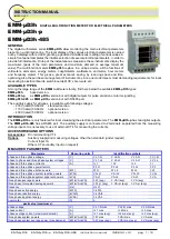
EMM-µD3h EMM-µD3h-p EMM-µD3h-485 instruction manual
IM380-U v3.1
pag. 1 / 12
INSTRUCTION MANUAL
IM380-U v3.1
EMM-µD3h
DIGITAL MULTIFUNCTION METER FOR ELECTRICAL PARAMETERS
EMM-µD3h-p
EMM-µD3h-485
GENERAL
The
digital
multimeters
series
EMM-µD3h
allow
monitoring
the
main
electrical
parameters
present
on
a
distribution
line.
The
local
display
of
the
various
electrical
parameters
is
carried
out
by
3
displays
with
red
LED,
granting
a
good
and
simultaneous
reading
of
various
values.
A
simple
front
panel
completes
the
intuitive
selection
of
several
electrical
parameters,
in
order
to
provide
full
information.On
top
of
the
instantaneous
measures,
these
instruments
display
the
maximums
(peak
of
the
main
parameters
and
maximum
demand
or
average
maximum
value).The
multifunction
meters
EMM-µD3h
replace
in
a
unique
device,
all
the
functions
of
voltmeters,
ammeters,
energy
meters,
cosphimeters,
wattmeter’s,
varmeters,
hour
meters
and
frequency
meters.
This
gives
a
great
economic
saving,
by
reducing
space
and
time,
optimising
also
the
purchase
management
of
instruments,
since
one
model
meets
most
demanding
requirements
for
local
measuring
in
electrical
boards,
switch-boards,
MCC’s,
Gen-sets,
etc.
AVAILABLE TYPES
Among the large range of the
EMM
multimeters family, find here below the available
EMM-µD3h
types:
EMM-µD3h
based version.
EMM-µD3h-p
as
EMM-µD3h
version but with digital outputs for pulse emission or alarm signalling.
EMM-µD3h-485
as
EMM-µD3h
version but with RS485 port.
The auxiliary supply for all types, is available with following voltages:
- 230V (rated) 50-60Hz
standard version
- 110V (rated) 50-60Hz
optional version
- 400V (rated) 50-60Hz
optional version
INTRODUCTION
The
EMM-µD3h
are only featured for local visualising the electrical parameters. The
EMM-µD3h-p
has two digital outputs.
The
EMM-µD3h-485
has a RS485 port. The auxiliary supply is connected to 2 terminals, separated from the measuring
voltage inputs. It is necessary to use of external CT’s for measuring the currents.
ACCESSORIES AND OPTIONS
Accessories
:
Din rail mounting CT’s
Options
:
Auxiliary supply and measuring voltages, other than standard (under request)
Current Input 1A
Others CT secondary input (on request)
MEASURED PARAMETERS
Parameters
Measuring units
Identification symbols
phase and three phase voltage
[V]
V L1-N
V L2-N
V L3-N
V L-N
phase to phase and three phase system voltages
[V]
V L1-L2
V L2-L3
V L3-L1
V L-L
phase and three phase currents
[A]
I L1
I L2
I L3
I
phase and three phase power factors
PF L1
PF L2
PF L3
PF
phase and three phase active powers
[kW]
W L1
W L2
W L3
W
phase and three phase system reactive powers
[kVAr]
VAr L1
VAr L2
VAr L3
VAr
phase and three-phase system apparent powers
[kVA]
VA L1
VA L2
VA L3
VA
three phase average powers
[kW-kVAr-kVA]
W (avg)
VAr (avg)
VA (avg)
three phase forecasted average powers
[kW-kVAr-kVA]
W pr (avg)
VAr pr (avg)
VA pr (avg)
frequency
[Hz]
Hz L1
three phase active energy
[kWh]
kWh
three phase reactive energy
[kVArh]
kVArh
three phase apparent energy
[kVAh]
kVAh
hour meter
[h]
h
peak value (maximums):
phase voltage
[V]
V L1-N max
V L2-N max
V L3-N max
phase current
[A]
I L1 max
I L2 max
I L3 max
phase average current (maximum demand)
[A]
I L1 max (avg)
I L2 max (avg)
I L3 max (avg)
three phase system powers
[kW-kVAr-kVA]
W max
VAr max
VA max
three phase system average power (max demand)
[kW-kVAr-kVA]
W max (avg)
VAr max (avg)
VA max (avg)


