background image

Cod. 4-329710E del 10/2014

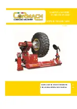
MONSTER AGTT

Italiano 

Manuale d’uso 

3

English 

Operator’s manual 

39

Français 

Manuel d’utilisation 

75

Deutsch Betriebsanleitung 

111

Español 

Manual de uso 

147

Summary of Contents for MONSTER AGTT

Page 1: ...Cod 4 329710E del 10 2014 MONSTER AGTT Italiano Manuale d uso 3 English Operator s manual 39 Français Manuel d utilisation 75 Deutsch Betriebsanleitung 111 Español Manual de uso 147 ...

Page 2: ...onique de reproduction et d adaptation totale ou partielle par n importe quel moyen y compris microfilms et copies photostatiques sont réservés Les informations contenues dans ce manuel sont sujettes à des variations sans préavis Alle Rechte der Übersetzung elektronischen Speicherung Vervielfältigung und Teil oder Gesamtanpassung unter VerwendungvonMittelnjedwederArt einschließlichMikrofilm und fo...

Page 3: ...E DEI PNEUMATICI 19 BLOCCAGGIO DELLE RUOTE 19 SMONTAGGIO RUOTE AGRICOLE 19 MONTAGGIO RUOTE AGRICOLE 21 SMONTAGGIO RUOTE TUBELESS E SUPERSINGLE 21 MONTAGGIO RUOTE TUBELESS E SUPERSINGLE 22 SMONTAGGIO RUOTE PER MOVIMENTO TERRA CON CERCHIETTO 22 MONTAGGIO RUOTE PER MOVIMENTO TERRA CON CERCHIETTO 23 RIGATURA DELLE COPERTURE 23 COMANDO DI ARRESTO E PROCEDURA DI EMERGENZA 23 MODI DI FUNZIONAMENTO 24 TAB...

Page 4: ...vo fornito assieme all apparecchiatura inunacartellinavicinoallamacchina peragevolarnelaconsultazione da parte degli operatori La documentazione tecnica fornita è parte integrante della macchina pertanto in caso di vendita dell apparecchiatura tutta la documentazione dovrà esservi allegata Il manuale è da ritenersi valido esclusivamente per il modello e la matricola macchina rilevabili dalla targh...

Page 5: ...ntazione descritte L inosservanza di tali raccomandazioni può provocare danneggiamenti alla macchina e pregiudicare la sicurezza dell operatore ATTENZIONE Prima di movimentare la macchina confrontare baricentro e peso della stessa con le capacità del sollevatore scelto Per lo spostamento della macchina imballata infilare le forche di un muletto negli appositi scassi posti sul basamento dell imball...

Page 6: ... e del carico massimo ammesso tenendo conto della base di appoggio al pavimento e degli eventuali mezzi di fissaggio previsti Posizionare la macchina in modo da garantire l accessibilità su tutti e quattro i lati In particolare verificare gli spazi minimi richiesti per il lavoro indicati in fig 6 anteriormente per il carico e lo scarico della ruota posteriormente per una buona visuale di lavoro IM...

Page 7: ...cavo di alimentazione una spina conforme alle normative vigenti collegare la macchina ad una propria connessione elettrica dotata di un apposito interruttore automatico differenziale con soglia di intervento di 100mA e di un inter ruttore automatico magnetotermico da 32A con curva di intervento di tipo D montare dei fusibili di protezione della linea di alimentazione dimensionati secon do le indic...

Page 8: ...esappianoutilizzare l apparecchiatura in modo corretto e sicuro e che vi sia un adeguata supervisione non toccare linee e parti interne di motori o apparecchiature elettriche senza prima assicurarsi che sia stata tolta tensione leggere con attenzione questo libretto e imparare ad usare la macchina correttamente e in sicurezza tenere sempre disponibile in luogo facilmente accessibile questo manuale...

Page 9: ... DATI TECNICI Larghezza massima 3065 mm Profondità massima 2600 mm Altezza massima 2150 mm Motore riduttore 2 2 kW Motore pompa idraulica 3 3 4 kW Peso macchina 1350 kg Dimensioni cerchio da 14 a 58 Diametro massimo ruote 2500 mm Peso massimo ruota 1700 kg Larghezza massima ruote 1600 mm capacità serbatoio olio 15 l Tipo di olio idraulico API CIS 32 AGIP OSO 32 Livello di rumorosità Livello di pre...

Page 10: ...in movimento della macchina ACCESSORI A RICHIESTA Si faccia riferimento all apposito catalogo accessori CONDIZIONI DI UTILIZZO PREVISTE Lo smontagomme è stato progettato esclusivamente per montare e smontare pneuma tici ATTENZIONE Ogni altro utilizzo diverso da quello descritto è da considerarsi improprio ed irragio nevole PERICOLO Non è prevista dal costruttore l operazione di gonfiaggio sulla ma...

Page 11: ...manutenzione A Interruttore generale B Manipolatore C Manometro D Punto per sollevamento E Centralina elettro idraulica F Autocentrante G Disco stallonatore H Utensile I Braccio utensili L Display M Side To Side N Potenziometro Avviare la macchina mediante l interruttore generale A fig 11 ed accertarsi che la rota zione del motore della centralina idraulica avvenga nella direzione indicata dalla f...

Page 12: ...icinarsi mentre vengono azionati i comandi relativi ai movimenti degli utensili ATTENZIONE Per evitare incidenti nell uso degli accessori in dotazione o a richiesta assicurarsi che le parti meccaniche applicate siano montate correttamente e ben fissate ai par ticolari Durante il lavoro impugnare con forza gli accessori manuali NOTA La macchina può essere utilizzata anche per la rigatura dei pneuma...

Page 13: ... tra gruppo utensili e cerchione o ruota bloccati sul mandrino auto centrante Mantenere la distanza di sicurezza durante il ribaltamento del gruppo utensili per evitare schiacciamenti Prima di compiere una qualsiasi operazione con gli utensili assicurarsi che i perni siano completamente a fine corsa nelle proprie sedi Controllare visivamente tramite le asole che i perni siano contro la parete Fig ...

Page 14: ...mittente all unita ricevente in seguito all azionamento di uno o più comandi Rimane acceso finché sono azionati dei comandi FUNZIONE DEL LED F Questo led si accende quando si preme il pulsante F e contemporaneamente uno dei tasti dove sono presenti le seconde funzioni In questo modo l operatore ha la conferma che il comando impartito alla macchina è la seconda funzione e non la funzione principale...

Page 15: ...ente nel momento in cui si collega scollega il cavo comandi Sul lato destro del quadro elettrico sono presenti tre led di colore verde bianco e rosso Il led verde LED PRESENZA CAVO si accende ogni volta che viene inserito il cavo co mandi e indica che la trasmissione avviene via cavo e non via radio Quando si scollega il cavo comandi il led si spegne e la macchina commuta automaticamente in ricezi...

Page 16: ...genza utensile 11 Pulsante di reset funzione 12 Pulsanti di impostazione diametro del cerchio 12a decrementa i valori 12b incrementa i valori 13 Pulsante di funzione da premere con pulsante 12a per memorizzare una posizione diversa da quelle pre impostate degli utensili pulsante 12b per commutare la dimensioni da pollici a millimetri e viceversa pulsante 14 15 per eseguire il comando side to side ...

Page 17: ...tare la rotazione del cerchio sulle griffe è indispensabile inserire il perno per ruote in lega in uno dei fori di fissaggio del cerchione A fig 17 ATTENZIONE Nel caso la macchina si comporti in modo anomalo portarsi a distanza di sicurezza e portare l interruttore generale della macchina A fig 18 in posizione 0 ATTENZIONE Assicurarsi che il bloccaggio del cerchione venga eseguito correttamente in...

Page 18: ...operative PERICOLO Quando si lavora con ruote aventi un diametro maggiore di 1500 mm oppure un peso maggiore di 200 kg durante la fase di caricamento bloccaggio ruota sull autocen trante è indispensabile operare in condizioni di sicurezza seguendo le indicazioni sotto riportate Ribaltare all indietro il braccio portautensili Montare la protezione anti ribaltamento ruote A fig 22 nell apposito allo...

Page 19: ... dimensione è già inserita basterà agire sul pulsante tangenza disco per portare in posizione la ruota rispetto al disco stallonatore fig 23 Se necessario è possibile avvicinare allontanare manualmente la ruota dal disco stal lonatore SMONTAGGIO RUOTE AGRICOLE STALLONATURA A pneumatico sgonfio far girare l autocentrante in continuazione facendolo avanzare a piccoli tratti mediante l apposito coman...

Page 20: ...à nella posizione originale e l utensile orizzontale Se presente la camera d aria appoggiare la ruota sul pavimento e far arretrare il cerchio ottenendo così lo spazio necessario per estrarla fig 31 SMONTAGGIO TALLONE POSTERIORE Agire sul comando S T S per portare il gruppo utensili dall altro lato della ruota A questo punto ruotare l autocentrante Portare il disco stallonatore nelle vicinanze del...

Page 21: ...i cerchi a doppio canale è consigliato l utilizzo dell accessorio DV120 fig 37 Neicerchiskidderèconsigliatol utilizzodelDV120assiemealmorsettoskidder entrambi accessori a richiesta SMONTAGGIO RUOTE TUBELESS E SUPERSINGLE Stallonare la parte anteriore del pneumatico e tenendo spinto il tallone nel canale lubrificare con il grasso la balconata del cerchio e il tallone fig 38 Ripetere la stallonatura...

Page 22: ...do il pneumatico in rotazione premere sul tallone anteriore fino a liberare il cer chietto e l anello di serraggio fig 42 se necessario posizionare il disco sul cerchietto e spingerlo verso il pneumatico fig 43 Tale operazione può essere agevolata grazie al movimentoidraulicodeldiscostallonatorechegarantiscesemprelaperfettainclinazione di stallonatura fig 44 L anello si libererà dal cerchietto e v...

Page 23: ...ieneruotandol interruttore generale fig 18 posto sulla scatola impianto elettrico in posizione zero Agendo sul pulsante di arresto si ottiene uno stop TEMPORANEO 20 secondi di tutti i comandi Sul display apparirà la scritta STOP Al termine dei 20 secondi la macchina ritornerà nella posizione di Stand By se invece vi sono comandi premuti continuerà a visualizzare la scritta Stop lampeggiante fino a...

Page 24: ...ei comandi Acceso fisso se cavo collegato spento altrimenti Messaggi variabili UTENTE FINALE In mancanza dei dati di calibrazione non sono utilizzabili gli automatismi ma solo i comandi manuali Lampeggio molto lento il ciclo on off dura 2 s Spento Acceso fisso se cavo collegato spento altrimenti Messaggi variabili oppure spento UTENTE FINALE Questa segna lazione può avvenire solamente all accensio...

Page 25: ...i errori impediscono di utilizzare gli automatismi della macchina ad es gli errori E00 ed E01 oppure ne causano la fine anticipata ad es l errore E11 Premendo il tasto Clear sul pannello comandi si cancella sul display il codice di errore ma non viene rimossa la causa dell errore per cui se si ripete il comando che lo ha generato il messaggio riapparirà ERRORE SIGNIFICATO AZIONE E00 Mancanza dei d...

Page 26: ...alida per tutti i modi di funzionamento vale quanto segue quando le cifre e o le scritte lampeggiano significa che il valore visualizzato deve essere confermato dall operatore o comunque che è attesa una azione da parte dell operato re SEGNALAZIONI ACUSTICHE In tutti i modi di funzionamento il display emette le segnalazioni acustiche indicate in tabella 3 Segnale acustico Significato Azione 1 bip ...

Page 27: ...che causano l attivazione del segnalatore acustico luminoso sono i seguenti Apertura chiusura autocentrante Sollevamento abbassamento autocentrante Sollevamento abbassamento braccio utensile disco stallonatore Tangenza disco stallonatore Tangenza utensile Side to Side RICERCA GUASTI La macchina non parte Mancanza di corrente Controllare il senso di rotazione del motore centralina idrulica Mancanza...

Page 28: ...a Il manipolatore non aziona la macchina Chiamare l Assistenza Tecnica Batterie scariche led giallo acceso Caricare batterie Chiamare l Assistenza Tecnica Assenza di pressione idraulica Pompa rotta Sostituire pompa Eccessivo rumore della centralina Giunto di collegamento usurato Sostituire giunto Funzionamento a scatti dei movimentI Mancanza di olio Portare a livello l olio Interruttore difettoso ...

Page 29: ...ella macchina fredda la traslazione veloce non è performante fare scaldare l olio per alcuni minuti tramite movimenti della macchina a velocità normale ATTENZIONE il libretto Pezzi di ricambio non autorizza l utente ad intervenire sulle macchine ad esclusione di quanto esplicitamente descritto nel manuale d uso ma consente all utente di fornire informazioni precise all assistenza tecnica al fine d...

Page 30: ... al tappo plastico devono rimanere 5cm 2inch ed eventualmente rabboccare con olio API CIS 32 AGIP OSO 32 o altro tipo equivalente Il controllo deve essere effettuato a cilindri chiusi appoggiando il tappo sul serbatoio senza avvitarlo Si consiglia comunque di sostituire l olio dopo 1500 ore di lavoro oppure una volta l anno PRODUTTORE TIPO DI OLIO AGIP OSO 32 ARNICA 68 ESSO NUTO H32 INVAROL EP 68 ...

Page 31: ...i materiali contenuti in questi prodotti A tale scopo i produttori e distributori delle apparecchiature elettriche ed elettroniche organizzano opportuni sistemi di raccolta e smaltimento delle apparecchiature stesse Alla fine della vita del prodotto rivolgetevi al vostro distributore per avere informazioni sulle modalità di raccolta Al momento dell acquisto di questo prodotto il vostro distributor...

Page 32: ...a inserite le nuove batterie si richiude il vano batterie e si procede con la carica ATTENZIONE Smaltire le pile usate come da normative vigenti INFORMAZIONI SULLA DEMOLIZIONE In caso di demolizione della macchina separare preventivamente i particolari elettrici elettronici plastici e ferrosi Procedere quindi alla rottamazione diversificata come pre visto dalle norme vigenti INDICAZIONI E AVVERTEN...

Page 33: ...all aria aperta e in seguito al presidio medico Occhi irrigareabbondantementeconacquaerivolgersialpiùprestoalpresidiomedico Pelle lavare con acqua e sapone MEZZI ANTINCENDIO DA UTILIZZARE Per la scelta dell estintore più adatto consultare la seguente tabella Materiali secchi Liquidi infiammabili Apparecchiature elettriche Idrico SI NO NO Schiuma SI SI NO Polvere SI SI SI CO2 SI SI SI ATTENZIONE Le...

Page 34: ... di attrezzature per la stallonatura e lo smontaggio delle coperture Manipolatore Unità di comando a distanza con il quale far compiere alla macchina tutti i movimenti necessari alle varie operazioni Rigatura Operazione di ripristino della scolpitura del battistrada del pneumatico Stallonatura interna esterna Distacco del tallone del pneumatico dal bordo del cerchione Side To Side Automatismo che ...

Page 35: ...Interruttore generale SQ3 Microinterruttore utensile in posizione orizzontale SQ4 Microinterruttore albero utensile ruotato a SX SQ5 Proximity switch passo catena TC1 Trasformatore YV1 Elettrovalvola bypass YV2 Elettrovalvola spostamento radiale autocentrante SU YV3 Elettrovalvola spostamento radiale autocentrante GIU YV4 Elettrovalvola traslazione SX braccio YV5 Elettrovalvola traslazione DX brac...

Page 36: ...ili GIU SA10 Contatto joystick rotazione SX braccio gruppo utensili SA11 Contatto joystick rotazione DX braccio gruppo utensili SA12 Contatto joystick disco stallonatore SU SA13 Contatto joystick disco stallonatore GIU SA14 Contatto joystick utensile GIU SA15 Contatto joystick utensile SU SA16 Deviatore tre posizioni selezione velocità motore rotazione autocentrante SB1 Pulsante di arresto SB2 Pul...

Page 37: ...Manuale d uso MONSTER AGTT 37 I Note ...

Page 38: ...38 Manuale d uso MONSTER AGTT Note ...

Page 39: ...NS 53 LUBRICATING TYRES 55 WHEEL LOCKING 55 DEMOUNTING AGRICULTURE WHEELS 55 MOUNTING AGRICULTURE WHEELS 57 DEMOUNTING TUBELESS AND SUPERSINGLE TYRES 57 MOUNTING TUBELESS AND SUPERSINGLE TYRES 58 DEMOUNTING WHEELS FOR EARTHMOVING MACHINES WITH A SIDE RING 58 MOUNTING WHEELS FOR EARTHMOVING MACHINES WITH A SIDE RING 59 TYRE GROOVING 59 STOP COMMAND AND EMERGENCY PROCEDURE 59 OPERATING MODES 60 DISP...

Page 40: ... changer where it is readily accessible for consultation by the machine operator The technical documentation supplied is considered an integral part of the machine and must always accompany the equipment if it is sold or transferred to a new owner The manual is only to be considered valid for the machine of the model and serial number indicated on the nameplate applied to it WARNING Comply with th...

Page 41: ...ling operations described Failure to comply with these instruction may damage the machine and risk the operator s safety WARNING Before handling the machine compare its barycentre and weight with the capacity of the lifter you have chosen To move the packaged machine insert the tines of a fork lift truck into the slots on the base of the packaging itself pallet Fig 2 WARNING The packaged machine m...

Page 42: ...quip ment plus the maximum load allowed taking into consideration also the resting base and any fixing means envisaged Position the machine in a manner that guarantees access to all four sides In particular check the minimum space required for the work indicated in Fig 6 at the front for wheel loading and unloading at the rear to be able to view the work being performed IMPORTANT for correct safe ...

Page 43: ...al safety standards connect the machine to its own electrical connection fitted with a suitable differential circuit breaker with an intervention threshold of 100mA and a 32A automatic thermal magnetic switch with a D type intervention curve mount power line protection fuses suitably sized according to the specifications indicated on the main wiring diagram contained in this manual install an effi...

Page 44: ...y trained that they are capable of using the machine correctly and safely and that they are adequately supervised during work do not touch power lines or the inside of electric motors or other electrical equipment before making sure that they have been powered off read this booklet carefully and learn how to use the machine correctly and safely always keep this operator manual in a place where it ...

Page 45: ...mum depth 2600 mm Maximum height 2150 mm Gear unit motor 2 2 kW Hydraulic pump motor 3 3 4 kW Machine weight 1350 kg Rim dimensions from 14 to 58 Maximum wheel diameter 2500 mm Maximum wheel weight 1700 kg Maximum wheel width 1600 mm Oil tank capacity 15 l Type of hydraulic oil API CIS 32 AGIP OSO 32 Noise level A weighted sound pressure level Lpa at the working position 70 dB A The noise levels i...

Page 46: ...rts OPTIONAL ACCESSORIES SUPPLIED ON REQUEST Please refer to the relevant accessories catalogue SPECIFIED CONDITIONS OF USE The tyre changer was designed exclusively for tyre mounting and demounting WARNING Any use other than those described in this manual is to be considered improper and unreasonable DANGER The manufacturer does not intend the machine to be used for inflation operations If the op...

Page 47: ...in switch B Control lever C Pressure gauge D Lifting point E Electrohydraulic power unit F Turntable G Bead breaker disc H Tool I Tool arm L Display M Side To Side N Potentiometer Start the machine with the main switch A Fig 11 and make sure that the hydraulic power unit motor is rotating in the direction indicated by the arrow A Fig 12 which can be seen on the motor cap Otherwise the rotation dir...

Page 48: ...proach the machine when the tool move ment commands are activated WARNING To prevent accidents when using the included or optional accessories make sure that the mechanical parts have been correctly installed and well fixed to the parts When working firmly grip the manual accessories NOTE The machine may also be used for tyre grooving For this operation the low speed should be selected WARNING Alw...

Page 49: ...ance to prevent crushing NEVER come between the tool unit and the rim or locked wheel on the turntable Keep a safe distance when the tool unit is tilting to prevent crushing Beforeperforminganyoperationwiththetools makesurethatthepinsarefullyinsertedin their seats Visually check through the slots that the pins are against the wall Fig 12 For safety reasons never leave the wheel locked on the turnt...

Page 50: ...lowing the activation of one or more commands It will remain on as long as the commands are activated FUNCTION OF THE F LED This LED turns on when the F key is pressed together with one of the keys that has a second function In this way the operator has the confirmation that the command given to the machine is the second function and not the main key function FUNCTION OF THE LOW BATT LED This LED ...

Page 51: ...s connected disconnected Three LEDS green white and red are located on the right side of the electrical board ThegreenLED CABLEPRESENCELED turnsoneachtimethecontrolcableisconnected and indicates that the transmission is taking place via cable and not via radio When the control cable is disconnected the LED turns off and the machine switches automatically to reception via radio The white LED RX ON ...

Page 52: ... Tool tangency dead man switch 11 Function reset button 12 Rim diameter setting buttons 12a decreases the values 12b increases the values 13 Function button to press with button 12a to store a position other than those preset for the tools button 12b to toggle between dimensions in inches and millimetres button 14 15 to perform the side to side command with tool unit rotation 14 Button to control ...

Page 53: ... on the clamps a pin for alloy wheels must be inserted in one of the rim fixing holes A fig 17 WARNING If the machine malfunctions retreat to a safe distance and turn the machine s main switch A Fig 18 to 0 WARNING Make sure that the rim is correctly and firmly locked on every gripping point of the turntable clamp WARNING Any operation intended to increase the maximum pressure setting value of the...

Page 54: ... mm or with a weight higher than 200 kg during the phase of loading locking the wheel on the turntable it is mandatory that you work in safe conditions following the instructions provided below Tip the tool holder arm backward Install the wheel anti tipping guard A Fig 22 in its housing Place the wheel in a vertical position Fig 22 so that its external side is next to the guard Activate the turnta...

Page 55: ...r disc If the dimension is already entered simply press the disc tangency button to position the wheel to the bead breaker disc fig 23 If necessary the wheel can be moved manually towards away from the bead breaker disc DEMOUNTING AGRICULTURE WHEELS BEAD BREAKING When the tyre is deflated turn the turntable in continuation moving it a little at a time using the specific control To make the bead br...

Page 56: ...n the rim will return to the original position and the tool will return horizontal If there is an inner tube place the wheel on the floor and move back the rim to create the space necessary to remove it Fig 31 REAR BEAD DEMOUNTING Use the S T S command to move the tool unit from the other side of the wheel At this point turn the turntable Move the bead breaker disc near the bead and start to push ...

Page 57: ...accessory DV120 fig 37 is recommended With skidder rims the use of DV120 is recommended together with the skidder terminal both of which are optional accessories DEMOUNTING TUBELESS AND SUPERSINGLE TYRES Break the front part of the tyre keeping the bead pushed in the well lubricate the shoul der of the rim and the bead with grease fig 38 Repeat the bead breaking operation in the rear Fig 39 To dem...

Page 58: ... ring and the lock ring fig 42 If necessary position the disc on the side ring and push it towards the tyre fig 43 This operation can be made easier thanks to the hydraulic movement of the bead breaker disc which always guarantees perfect bead breaking inclination fig 44 The ring will be freed from the side ring and will be extracted using the specific lever fig 45 Repeatthebeadbreakingoperationon...

Page 59: ...y turning the main switch Fig 18 located on the electric system box to zero Pressing the stop button makes all controls stop TEMPORARILY 20 seconds STOP will appear on the display After 20 seconds the machine will return to the Stand By position if commands are pressed Stop will remain displayed flashing until they are released All the commands located on the control lever are interrupted by relea...

Page 60: ...shes upon arrival of the com mands On steady if the cable is con nected otherwise off Variable messages FINAL USER If there is no cali bration data the automatisms cannot be used but only the manual com mands Flashes very slowly the on off cycle lasts 2 s Off On steady if the cable is con nected otherwise off Variable messages or off FINAL USER This signal will appear only upon start up and indica...

Page 61: ...ly i e error E11 Pressing the Clear key on the control panel cancels the error code on the display but if the cause of the error is not removed and the command that generated it is repeated the message will reappear ERROR MEANING ACTION E00 No calibration data Calibrate the machine If the error remains replace the board CPU RX2 This signal appears also when a new board is installed E01 No signal o...

Page 62: ...ired ACOUSTIC SIGNALS In all operating modes the display emits the acoustic signals specified in table 3 Acoustic signal Meaning Action 1 short bip Button pressed confirmation for memory setting deleting inch mm selection None 2 short bips Not used None 1 short bip 1 long bip Confirmation The action was completed successfully None 3 short bips Failed The action was not completed successfully or th...

Page 63: ...ble lifting lowering Tool arm bead breaker disc lifting lowering Bead breaker disc tangency Tool tangency Side To Side TROUBLE SHOOTING The machine does not start No current Check the rotation direction of the hydraulic power unit motor No current provide power The overload cut motor protector s is are not active Activate the overload cut motor protector s Transformer fuse burnt out Replace the fu...

Page 64: ... control lever does not operate the machine Contact Technical Assistance Batteries run down yellow LED on Charge the batteries Contact Technical Assistance No hydraulic pressure Pump broken Replace the pump Excessive control unit noise Worn connection joint Replace the joint Jerky movements Not enough oil Top up the oil Switch on control lever defective Replace the switch Presence of radio interfe...

Page 65: ...ance When turning on the cold machine quick translation does not work well heat up the oil for a few minutes by moving the machine at a normal speed WARNING The Spare parts handbook does not authorise users to carry out work on the machine with the exception of those operations expressly described in the user manual It only enables users to provide the technical assistance service with precise inf...

Page 66: ...o the plastic cap there must be 5cm 2 inch Top up with API CIS 32 AGIP OSO 32 oil or another equivalent type if necessary The check must be performed with the cylinders closed placing the cap on the tank without tightening it It is recommended to replace the oil in any case after 1500 hours of operation or once a year MANUFACTURER TYPE OF OIL AGIP OSO 32 ARNICA 68 ESSO NUTO H32 INVAROL EP 68 FINA ...

Page 67: ...ecover recycle and reuse many of the materials contained in these products Electrical and electronic manufacturers and distributors set up proper collection and treatment systems for these products for this purpose At the end of the product s working life contact your supplier for information about disposal procedures When you purchase this product your supplier will also inform you that you may r...

Page 68: ...he new batteries close the battery compartment and charge IMPORTANT Dispose of used batteries in accordance with applicable legislation INFORMATION ABOUT DEMOLITION If the machine is to be scrapped remove all electrical electronic plastic and metal parts and dispose of them separately in accordance with current provisions as prescribed by law INFORMATION AND WARNINGS ABOUT HYDRAULIC FLUID Disposin...

Page 69: ...Swallowing go to Casualty with the characteristics of the type of oil swallowed Inhalation in case of exposure to strong concentration of vapours or mists take the affected person out into the open air and then to Casualty Eyes rinse with plenty of water and go to Casualty as soon as possible Skin wash with soap and water RECOMMENDED FIRE EXTINGUISHING EQUIPMENT For the choice of the most suitable...

Page 70: ...ly consisting of an electric motor and a hydraulic pump Tool unit Group of equipment for tyre bead breaking and demounting Control lever Remote control unit used to make the machine perform all the movements necessary for the various operations Grooving Operation for restoring the groves in the tyre tread Inner outer bead breaking Separation of the tyre bead from the rim edge Side To Side Automati...

Page 71: ...e clamp motor QS1 Main switch SQ3 Tool micro switch in a horizontal position SQ4 Tool shaft micro switch turned to the left SQ5 Proximity switch chain pitch TC1 Transformer YV1 Bypass solenoid valve YV2 Turntable UP radial movement solenoid valve YV3 Turntable DOWN radial movement solenoid valve YV4 LH arm translation solenoid valve YV5 RH arm translation solenoid valve YV6 Lift wheel solenoid val...

Page 72: ...oystick contact SA10 Tool unit arm LH translation joystick contact SA10 Tool unit arm RH translation joystick contact SA12 Bead breaker disc UP joystick contact SA13 Bead breaker disc DOWN joystick contact SA14 Tool DOWN joystick contact SA15 Tool UP joystick contact SA16 Three way turntable rotation motor speed selection switch SB1 Stop button SB2 Turntable tool holder arm second translation spee...

Page 73: ...Operator s manual MONSTER AGTT 73 UK Notes ...

Page 74: ...74 Operator s manual MONSTER AGTT Notes ...

Page 75: ... ROUES 91 DEMONTAGE ROUES AGRICOLES 91 MONTAGE DES ROUES AGRICOLES 93 DEMONTAGE DES ROUES TUBELESS ET SUPERSINGLE 93 MONTAGE DES ROUES TUBELESS ET SUPERSINGLE 94 DEMONTAGE DES ROUES POUR VEHICULES DE CHANTIER AVEC TRINGLE 94 MONTAGE DES ROUES POUR VEHICULES DE CHANTIER AVEC TRINGLE 95 RAINURAGE DES PNEUS 95 COMMANDE D ARRET ET PROCEDURE D URGENCE 95 MODES DE FONCTIONNEMENT 96 TABLEAU DES ALARMES E...

Page 76: ...ion fournie avec la machine dans une pochette près de la machine afin que les opérateurs puissent facilement le consulter à tout moment Ce manuel et toute la documentation technique jointe font partie intégrante de la ma chine par conséquent ils doivent toujours l accompagner même en cas de changement de propriétaire Ce manuel n est valable que pour le modèle et le numéro série de la machine repor...

Page 77: ...près Le non respect de ces instructions peut provoquer des dommages à la machine et compromettre la sécurité de l opérateur ATTENTION Avant de déplacer la machine comparer le barycentre et le poids de celle ci avec la capacité de l élévateur choisi Pour le déplacement de l emballage enfiler les fourches d un gerbeur dans les trous respectifs situés à la base de l emballage palette fig 2 ATTENTION ...

Page 78: ...labased appui au sol et des éventuels dispositifs de fixation prévus Positionner la machine de façon à en garantir l accessibilité aux quatre cotés de celle ci Vérifier en particulier les espaces minimums requis pour le travail indiqués dans la fig 6 à l avant pour le chargement et le déchargement de la roue à l arrière pour une bonne vision de travail IMPORTANT Pour une utilisation en toute sécur...

Page 79: ...x réglementations en vigueur brancher la machine à une prise équipée d un disjoncteur différentiel ayant un seuil de déclenchement de 100mA et d un interrupteur magnéto thermique de 32A ayant une courbe de déclenchement de type D monterdesfusiblesdeprotectionàlaligned alimentation enrespectantlesintensités indiquées sur le schéma électrique général contenu dans le présent manuel disposer d une ins...

Page 80: ... il y ait une supervision adéquate nepastoucherleslignesetlespartiesinternesdemoteursoud instrumentsélectriques sans s assurer préalablement que le courant ait été coupé lireattentivementetassimilerlecontenudecemanueletsefamiliariseraveclamachine de façon à l utiliser correctement et en toute sécurité toujours garder ce Manuel d utilisation dans un endroit facilement accessible et ne pas hésiter à...

Page 81: ... maximum 2 150 mm Moteur réducteur 2 2 kW Moteur pompe hydraulique 3 3 4 kW Poids machine 1 350 kg Dimensions de la jante de 14 à 58 Diamètre maximum roues 2 500 mm Poids maximum roue 1700 kg Largeur maximum roues 1600 mm Capacité du réservoir d huile 15 l Type d huile hydraulique API CIS 32 AGIP OSO 32 Niveau de bruit Niveau de pression sonore pondéré A Lpa sur le lieu de travail 70 dB A Les vale...

Page 82: ...toutes les parties en mouvement de la machine EQUIPEMENT SUR DEMANDE Se reporter au catalogue spécial des accessoires USAGE PREVU Le démonte pneus a été conçu uniquement pour monter et démonter des pneus ATTENTION Toute autre usage est à considérer comme impropre et déraisonnable DANGER L opération de gonflage sur la machine n est pas prévue par le fabricant Si l opérateur décide avec son propre é...

Page 83: ...soumis à un entretien périodique A Interrupteur principal B Manipulateur C Manomètre D Point de levage E Centrale électro hydraulique F Autocentreur G Disque détalonneur H Outil I Bras d outils L Afficheur M Side To Side N Potentiomètre Démarrer la machine au moyen de l interrupteur général A fig 11 et s assurer que le moteur de la centrale hydraulique tourne dans la direction indiquée par la flèc...

Page 84: ...ocher quand les com mandes relatives aux mouvements des outils sont actionnées ATTENTION Pour éviter d éventuels accidents lors de l utilisation de l équipement de série ou en option s assurer que les parties mécaniques ajoutées soient correctement montées et bien fixées à la structure Pendant le travail empoigner avec force les accessoires manuels REMARQUE La machine peut également être utilisée ...

Page 85: ...erposer entre le groupe des outils et la jante ou la roue bloquée sur le mandrin autocentreur Garder toujours la distance de sécurité pendant le basculement du groupe des outils pour éviter l écrasement Avant d effectuer n importe quelle opération avec les outils contrôler si les pivots sont bien en fin de course dans leurs sièges Contrôler visuellement par les fentes si les pivots sont bien contr...

Page 86: ...ement d une ou plusieurs commandes Elle reste allumée tant que des commandes sont actionnées FONCTION DE LA DEL F Cette DEL s allume à l actionnement simultané du bouton F et de l une des touches des deuxièmes fonctions De cette manière l opérateur est sûr que la commande donnée à la machine est la deuxième fonction et non pas la fonction principale de la touche FONCTION DE LA DEL LOW BATT Cette D...

Page 87: ...e côté droit du tableau électrique La DEL verte DEL PRESENCE CABLE s allume à chaque connexion du câble des commandes et signale que la transmission s effectue via câble et pas via radio Lors du débranchement du câble des commandes la DEL s éteint et la machine commute automatiquement en réception via radio La DEL blanche DEL RX ON se met à clignoter lorsque l unité RX reçoit les commandes via câb...

Page 88: ... Bouton homme mort position tangente outil 11 Bouton de reset fonction 12 Boutons de mise au point du Ø de la jante 12a diminue les paramètres 12b augmente les paramètres 13 Bouton de fonction à appuyer en même temps que bouton 12a pour enregistrer une position des outils différente de celles prédéfinies bouton 12b pour commuter l unité de mesure pouces millimètres bouton 14 15 pour actionner la c...

Page 89: ...t une jante REMARQUE Si on travaille sur des jantes en alliage léger nous conseillons d utiliser les griffes ou les anneaux prévus à cet effet pouvant être fournis en option fig 16 afin d éviter des rayures ou des éraflures sur la jante même Pour éviter la rotation de la jante sur les griffes il faut absolument positionner le pivot pour jantes en alliage dans l un des trous de fixation de la jante...

Page 90: ...oids supérieur à 500 kg il est conseillé d utiliser un chariot élévateur ou une grue Ne pas laisser la roue bloquée sur l autocentreur pour des pauses plus longues que celles nécessaires aux opérations DANGER Lorsque on travaille avec des roues ayant un diamètre supérieur à 1 500 mm ou bien un poids supérieur à 200 kg pendant la phase de chargement blocage de la roue sur l autocentreur il est indi...

Page 91: ... sur la touche tangence disque pour positionner la route par rapport au disque détalonneur fig 23 En cas de besoin il est possible d approcher ou d éloigner manuellement la roue du disque détalonneur DEMONTAGE ROUES AGRICOLES DETALONNAGE Lorsque le pneu est dégonflé faire tourner l autocentreur en continuation en le faisant avancer par petits à coups à l aide de la commande prévue à cet effet Pour...

Page 92: ...position d origine et l outil horizontal S il y a la chambre à air appuyer la roue au sol et faire reculer la jante de façon à obtenir l espace nécessaire pour extraire facilement celle ci fig 31 DEMONTAGE TALON ARRIERE Actionner la commande S T S pour amener le groupe outils de l autre côté de la roue A ce point faire tourner l autocentreur Porter le disque détalonneur près du talon et commencer ...

Page 93: ...ARQUE Avec les jantes à double creux se servir de l accessoire DV120 fig 37 Dans les jantes skidder il est conseillé d utiliser l outil DV120 en même temps que l étau skidder il s agit d équipement en option DEMONTAGE DES ROUES TUBELESS ET SUPERSINGLE Détalonner la partie avant du pneu tout en tenant enfoncé le talon dans le creux de la jante graisser avec un lubrifiant le rebord de la jante fig 3...

Page 94: ...ur En gardant le pneu en rotation appuyer sur le talon avant jusqu à dégager la tringle et l anneau de serrage fig 42 si nécessaire mettre le disque sur la tringle et le pousser vers le pneu fig 43 Cette opération peut être facilitée grâce au mouvement hydraulique du disque détalonneur qui garantit toujours la bonne inclinaison de détalonnage fig 44 L anneau se dégagera de la tringle et sera extra...

Page 95: ...général fig 18 se trouvant sur la boîte du circuit électrique sur la position zéro L actionnementduboutond arrêtprovoquel arrêtTEMPORAIRE 20secondes detoutes lescommandes L indication STOP s afficheàl écran Auboutdes20secondes lamachine revient en position de stand by En revanche si des boutons sont actionnés l indication Stop continuera à clignoter jusqu à ce que lesdits boutons seront relâchés T...

Page 96: ...écep tion des commandes Allumée fixe si le câble est branché Sinon éteinte Messages variables UTILI SATEUR FINAL En absence des données d étalon nage les automa tismes ne sont pas disponibles mais seulement les com mandes manuelles Clignote ment très lent le cycle ON OFF dure 2 secondes Eteinte Allumée fixe si le câble est branché Sinon éteinte Messages varia bles ou éteinte UTILI SATEUR FINAL Cet...

Page 97: ... la fin ex l alarme E11 La pression de la touche Clear sur le tableau de commandes efface le code de l alarme à l écran mais n en élimine pas la cause Par conséquent si la commande ayant provoqué l affichage de l alarme est réactionnée le message s affichera à nouveau ALARME SIGNIFICATION ACTION E00 Absence des données d étalonnage Etalonner la machine Si l alarme persiste changer la carte CPU RX2...

Page 98: ... tous les modes de fonctionnement l afficheur émet des avertissements sonores décrits dans le tableau 3 Avertissement sonore SIGNIFICATION ACTION 1 bip bref Confirme la pression des boutons de paramétrage effacement mémoire sélection pouces mm Aucune 2 bips brefs Inutilisé Aucune 1 bip bref 1 bip long Confirmation L action effectuée a abouti Aucune 3 bips brefs Refus L action effectuée n a pas abo...

Page 99: ...sement de l autocentreur Soulèvement Abaissement du bras outil disque détalonneur Tangence disque détalonneur Tangence outil Side to Side RECHERCHE DES PANNES La machine ne démarre pas Courant manquant Vérifier le sens de rotation du moteur de la centrale hydraulique Absence d alimentation alimenter Le s disjoncteur s de protection du moteur ne fonctionnent pas Réenclencher le ou les disjoncteurs ...

Page 100: ...de l électrovanne Le manipulateur n actionne pas la machine Contacter le centre SAV le plus proche Batterie déchargée DEL jaune allumée Recharger la batterie Contacter le centre SAV le plus proche Absence de pression hydraulique Pompe défectueuse Remplacer la pompe Bruit excessif de la centrale Joint de branchement usé Remplacer le joint Fonctionnement saccadé des mouvements Manque d huile Porter ...

Page 101: ...achine travaille à froid faire chauffer l huile pendant quelques minutes en utilisant les mouvements de la machine à vitesse normale ATTENTION Le livret Pièces détachées n autorise pas l utilisateur à intervenir sur les machines sauf pour ce qui est explicitement décrit dans le manuel d utilisation mais elle lui permet de fournir des informations précises au SAV afin de réduire les temps d in terv...

Page 102: ...e fig 53 de la jauge mouillée au bouchon en plastique il ne doit rester que 5 cm 2 inch faire éventuellement l appoint avec de l huile API CIS 32 AGIP OSO 32 ou de marque équivalente Le contrôle doit être effectué avec les cylindres fermés en posant le bouchon sur le réservoir sans le visser On conseille cependant de remplacer l huile après 1 500 heures de travail ou bien une fois par an PRODUCTEU...

Page 103: ...nt et la santé humaine Une gestion correcte du produit en fin de vie permet de participer à la récupération au recyclage et à la réutilisation de la plupart des matériaux entrant dans sa composition Danscetteoptique lesfabricantsetlesvendeursd appareillagesélectriquesetélectroni ques ont mis en place des systèmes de collecte et de retraitement desdits appareils S adresser donc à son propre vendeur...

Page 104: ...onafind opérerpluscommodémentetdansunezone éclairée Après avoir introduit les piles neuves refermer le logement et procéder à la charge ATTENTION Les piles usées doivent être traitées confor mément à la législation locale en vigueur en la matière INFORMATIONS CONCERNANT LA DEMOLITION En cas de démolition de la machine séparer les pièces électriques électroniques en plastique et en fer Mettre au re...

Page 105: ... mettre des tabliers résistants aux huiles minérales installer des écrans de protection en cas d éclaboussures Huile minérale premiers secours Huile minérale premiers secours Ingestion contacter le service médical d urgence en lui fournissant toutes les informa tions sur le type d huile ingéré Inhalation en cas d exposition à de fortes concentrations de vapeurs ou de brouillard huileux placer le b...

Page 106: ...Elément mécanique crocheté pour maintenir ou transporter Groupe Pompe Ensemble composé d un moteur électrique et d une pompe hydraulique Groupe outils Ensemble d équipements servant au détalonnage et au démontage des pneus Manipulateur Unité de commande à distance grâce à laquelle il est possible de faire faire à la machine tous les mouvements nécessaires pour les différentes opérations Rainurage ...

Page 107: ...e hydraulique M2 Moteur étau autocentreur QS1 Disjoncteur général SQ3 Microinterrupteur outil en position horizontal SQ4 Microinterrupteur arbre outil tourné à gauche SQ5 Capteur proximité pas chaîne TC1 Transformateur YV1 Electrovanne by pass YV2 Electrovanne déplacement radial autocentreur EN HAUT YV3 Electrovanne déplacement radial autocentreur EN BAS YV4 Electrovanne mouvement G bras YV5 Elect...

Page 108: ...tils BAS SA10 Contact joystick rotation GAUCHE bras groupe outils SA11 Contact joystick rotation DROITE bras groupe outils SA12 Contact joystick disque détalonneur EN HAUT SA13 Contact joystick disque détalonneur EN BAS SA14 Contact joystick outil BAS SA15 Contact joystick outil HAUT SA16 Commutateur trois positions sélection vitesse moteur rotation autocentreur SB1 Bouton d arrêt SB2 Bouton deuxi...

Page 109: ...Manuel d utilisation MONSTER AGTT 109 F Remarques ...

Page 110: ...110 Manuel d utilisation MONSTER AGTT Remarques ...

Page 111: ...REIFEN 127 EINSPANNEN DER RÄDER 127 DEMONTAGE RÄDER LANDWIRTSCHAFTLICHER FAHRZEUGE 127 MONTAGE RÄDER LANDWIRTSCHAFTLICHER FAHRZEUGE 129 DEMONTAGE SCHLAUCHLOSE UND SUPERSINGLE REIFEN 129 MONTAGE SCHLAUCHLOSE UND SUPERSINGLE REIFEN 130 DEMONTAGE DER RÄDER FÜR ERDBEWEGUNGSMASCHINEN MIT SPRENGRING 130 MONTAGE DER RÄDER FÜR ERDBEWEGUNGSMASCHINEN MIT SPRENGRING 131 PROFILIERUNG DER REIFEN 131 ANHALTEBEF...

Page 112: ... Das Handbuch mitsamt dem beigepackten Bildmaterial ist in einer Dokumen tentasche griffbereit an der Maschine aufzubewahren um den Bedienern die Einsicht zu erleichtern Die mitgelieferte technische Dokumentation ist integrierender Bestandteil der Maschine und muss dieser bei Verkauf beigefügt werden Das Handbuch hat nur für das Modell und die Seriennummer die auf dem daran ange brachten Schild st...

Page 113: ...n Die Nicht beachtung dieser Empfehlungen kann zu schweren Schäden an der Maschine führen und die Sicherheit des Bedieners beeinträchtigen ACHTUNG Bevor die Maschine bewegt wird ihren Schwerpunkt und das Gewicht mit der Trag fähigkeit der gewählten Hebevorrichtung vergleichen Für den Transport der verpackten Maschine die Gabeln eines Gabelstaplers in die Gabeltaschen im unteren Bereich der Verpack...

Page 114: ... Summe des Eigengewichts des Geräts und der maximal zulässigen Last entsprechen Dabei müssen die Auflagefläche am Boden und die eventuell vorgesehenen Befestigungsmittel mit berücksichtigt werden DieMaschinesoaufstellen dasssievonallenvierSeitenauszugänglichist Insbesonderediefür die Arbeit erforderlichen Mindestfreiräume beachten die auf Abb 6 angegeben werden vorne für das Auf und Abladen des Ra...

Page 115: ...rmgerechter Stecker anzubringen DieMaschineaneineneigenenelektrischenAnschlussmit Fehlerstromschutzschalter mit Auslöseschwelle von 100mA und Leitungsschutzschalter 32A mit Auslösecharak teristik vom Typ D anschließen Die Schutzsicherungen der Stromleitung montieren die entsprechend der Angaben auf dem in diesem Handbuch enthaltenen elektrischen Schaltplan bemessen sein müssen Die Elektroanlage de...

Page 116: ...ngen installiert wurde Sicherzustellen dass alle Maschinenbediener für eine korrekte und sichere Bedienung der Maschine ausreichend ausgebildet sind und hierüber Aufsicht geführt wird keine Leitungen und Innenteile von elektrischen Motoren oder elektrischen Geräten zu berühren ohne sich vorher davon überzeugt zu haben dass der Strom abgeschaltet ist das vorliegende Handbuch aufmerksam durchzulesen...

Page 117: ...mit dem Rad in senkrechter Position und wird vom Bediener mit Hilfe der mobilen Steuereinheit bedient TECHNISCHE DATEN Maximale Breite 3065 mm Maximale Tiefe 2600 mm Maximale Höhe 2150 mm Getriebemotor 2 2 kW Motor der Hydraulikpumpe 3 3 4 kW Maschinengewicht 1350 kg Felgengrößen von 14 bis 58 Maximaler Raddurchmesser 2500 mm Max Radgewicht 1700 Kg Maximale Radbreite 1600 mm Fassungsvermögen Ölbeh...

Page 118: ...hinen die solche verwenden Artikelnr 435443 Schmierpresse Die Schmierpresse dient zur Schmierung der sich in Bewegung befindlichen Maschi nenteile die einmal monatlich empfohlen wird OPTIONALE ZUBEHÖRTEILE Bitte auf den entsprechenden Zubehörkatalog Bezug nehmen VORGESEHENER GEBRAUCH Die Reifenmontiermaschine wurde ausschließlich für die Montage und Demontage von Reifen entwickelt ACHTUNG Jeder an...

Page 119: ...llen und Verletzungen muss die Maschine zweckgerecht installiert ordnungsgemäß eingesetzt und planmäßig gewartet werden A Hauptschalter B Bedienpult C Manometer D Anhebepunkt E Elektrohydraulisches Aggregat F Spannteller G Abdrückscheibe H Werkzeug I Werkzeugarm L Display M Side To Side N Potentiometer Die Maschine mit Hilfe des Hauptschalters A Abb 11 starten und sicherstellen dass sich der Motor...

Page 120: ...verhindern Das Annähern während der Steuerung der Werkzeugbewegungen ist verboten ACHTUNG Um Unfälle bei der Benutzung des mitgelieferten oder optionalen Zubehörs zu ver meiden sicherstellen dass die angewandten mechanischen Teile korrekt montiert und fest an den Einzelteilen verankert sind Die manuellen Zubehörteile während der Arbeit gut festhalten HINWEIS Die Maschine kann auch für die Profilie...

Page 121: ... und der am Spannteller einge spannten Felge oder dem am Spannteller eingespannten Rad stellen Zur Vermeidung einer möglichen Einklemmgefahr den Sicherheitsabstand während des Kippens der Werkzeuggruppe beibehalten Bevor der Bediener eine Arbeit mit Werkzeugen ausführt muss er sicherstellen dass sich die Bolzen bis zum Anschlag in ihren Sitzen befinden Eine Sichtkontrolle über die Schlitze durchfü...

Page 122: ...ss eine Datenübertragung von der Sendeeinheit zur Emp fangseinheit in Folge der Betätigung einer oder mehrerer Steuerungen läuft Sie leuchtet so lange so lange Steuerungen betätigt werden FUNKTION DER LED F Diese Led leuchtet auf wenn gleichzeitig die Taste F und eine der Tasten mit zweiter Funktion gedrückt werden So wird dem Bediener bestätigt dass der erteilte Befehl die zweite Funktion und nic...

Page 123: ...els Auf der rechten Seite des Schaltschranks befinden sich eine grüne eine weiße und eine rote Led Die grüne Led LED KABELPRÄSENZ leuchtet jedes Mal auf wenn das Steuerkabel angeschlossen wird und zeigt an dass die Übertragung per Kabel und nicht per Funk erfolgt WenndasSteuerkabelabgetrenntwird schaltetsichdieLedausunddieMaschine schaltet automatisch auf Funkempfang um Die weiße Led LED RX ON bli...

Page 124: ... Taste für die Abdrückscheibenannäherung 10 Totmann Taste für die Werkzeugannäherung 11 Taste zur Rücksetzung der Funktion 12 Tasten zur Einstellung des Felgendurchmessers 12a verringert die Werte 12b erhöht die Werte 13 Funktionstaste zu drücken mit Taste 12a zur Speicherung einer nicht voreingestellten Position der Werkzeuge Taste 12b zum Umschalten der Abmessungen zwischen Zoll und Millimeter T...

Page 125: ...chtmetallfelgen müssen die vorgesehenen Spannklauen benutzt werden die auf Anfrage geliefert werden Abb 16 um Kratzer und Beulen an der Felge zu vermeiden Um das Drehen der Felge auf den Spannklauen zu vermeiden muss unbedingt der Bol zen für Leichtmetallfelgenräder in eine der Befestigungsbohrungen der Felge gesteckt werden A Abb 17 ACHTUNG Falls die Maschine sich anormal verhält gehen Sie auf Si...

Page 126: ... empfohlen Das Rad nie länger als für die betriebsbedingt unbedingt notwendigen Pausen auf dem Spannteller eingespannt lassen GEFAHR Beim Arbeiten mit Rädern mit einem Durchmesser von über 1500 mm oder einem Gewicht von über 200 kg müssen beim Aufladen und Einspannen des Rads auf dem Spannteller unbedingt die folgenden Anweisungen befolgt werden um sichere Ar beitsbedingungen zu garantieren Den We...

Page 127: ...bdrückscheibe angenähert Wenn der Durchmesser bereits eingegeben wurde reicht es die Taste Scheibenannähe rung zu betätigen um das Rad an der Abdrückscheibe zu positionieren Abb 23 Falls notwendig kann das Rad manuell der Abdrückscheibe angenähert bzw von dieser entfernt werden DEMONTAGE RÄDER LANDWIRTSCHAFTLICHER FAHRZEUGE ABDRÜCKEN Mit luftleerem Reifen den Spannteller fortwährend drehen lassen ...

Page 128: ...e kehrt in die ursprüngliche Postion und das Werkzeug in die Waagrechte zurück BeivorhandenemSchlauchdasRadaufdenBodenlegenunddieFelgezurückschieben um genug Platz zum Herausziehen zu haben Abb 31 DEMONTAGE HINTERER WULST Auf die Steuerung S T S einwirken um die Werkzeuggruppe auf die andere Seite des Rads zu bringen An dieser Stelle den Spannteller drehen DieAbdrückscheibeinWulstnähebringenunddam...

Page 129: ...37 empfohlen Bei Skidder Felgen wird die Verwendung des Zubehörs DV120 gemeinsam mit der Skidder Spannbacke empfohlen beides sind optionale Zubehörteile DEMONTAGE SCHLAUCHLOSE UND SUPERSINGLE REIFEN Den vorderen Teil des Reifens abdrücken und den Wulst in das Felgenbett gedrückt halten das Felgenhorn Abb 38 und den Wulst mit Fett schmieren Auch den hinteren Teil abdrücken Abb 39 Für die Demontage ...

Page 130: ...g und der Anzugsring frei sind Abb 42 gegebenenfalls die Abdrückscheibe am Sprengring posi tionieren und Richtung Reifen drücken Abb 43 Dieser Arbeitsvorgang kann durch die hydraulische Bewegung der Abdrückscheibe erleichtert werden die immer eine perfekte Abdrückneigung garantiert Abb 44 Der Ring löst sich aus dem Sprengring und wird dann mit dem vorgesehenen Hebel herausgezogen Abb 45 Das Abdrüc...

Page 131: ...ellungdesHaupt schalters Abb 18 am Schrank der Elektroanlage in die Nullstellung erreicht Bei Betätigung der Stopptaste erfolgt eine ZEITWEILIGE Unterbrechung 20 Sekunden aller Befehle Auf dem Display wird die Schrift STOP angezeigt Nach Ablauf der 20 Se kunden kehrt die Maschine in die Standby Position zurück wenn hingegen Steuerungen gedrückt sind blinkt die Schrift Stop bis die Steuerungen losg...

Page 132: ...cht benutzt werden es können nur manuelle Steue rungen erfolgen Blinkt schnell bis zur Ausschaltung der Maschine sobald ein automatischer Vorgang abge rufen wird Blinkt beim Eingang der Befehle Leuchtet wenn Kabel angeschlos sen andernfalls ausgeschalten Variable Meldungen ENDBE NUTZER Falls die Kalib rierdaten nicht vorhanden sind können die automati schen Vorgänge nicht benutzt werden es können ...

Page 133: ...dernormalenBetriebsart NORMALMODE könneneinigeFehlereintreten die in der Tabelle 2 beschrieben werden Der Fehlercode wird auf dem Display angezeigt Ei nigeFehlerverhinderndieBenutzungderautomatischenVorgängederMaschine z B die Fehler E00 und E01 oder führen zu deren verfrühter Beendigung z B der Fehler E11 DurchBetätigungderTasteClearaufderBedientafelwirdderFehlercodeaufdemDisplay gelöscht aber di...

Page 134: ...es für alle Betriebsarten Wenn die Ziffern und oder Schriften blinken bedeutet das dass der angezeigte Wert vom Bediener bestätigt werden muss oder in jedem Fall eine Handlung des Bedieners erwartet wird AKUSTIKMELDUNGEN In allen Betriebsarten gibt das Display die in der Tabelle 3 angeführten Akustikmeldun gen Akustisches Signal Bedeutung Abhilfe 1 kurzer Piepton Bestätigung des Tastendrucks für E...

Page 135: ...ie folgenden Befehle führen zum Auslösen des Akustik Leuchtmelders Öffnen Schließen des Spanntellers Anheben Absenken des Spanntellers Anheben Absenken von Werkzeugarm Abdrückscheibe Abdrückscheibenannäherung Werkzeugannäherung Side To Side FEHLERSUCHE Die Maschine startet nicht Kein Strom vorhanden Die Drehrichtung des Motors des Hydraulikaggregats kontrollieren Kein Strom vorhanden Strom zuführe...

Page 136: ...Bedienpult setzt die Maschine nicht in Betrieb Technischen Kundendienst verständigen Batterien leer gelbe Led leuchtet Batterien laden Technischen Kundendienst verständigen Kein Hydraulikdruck Pumpe defekt Pumpe ersetzen Aggregat arbeitet sehr laut Verbindungsstück verschlissen Verbindungsstück ersetzen Ruckartige Bewegungen Zu wenig Öl vorhanden Öl auffüllen Schalter am Bedienpult defekt Schalter...

Page 137: ...Kundendienst verständigen Beim Einschalten der kalten Maschine funktioniert die schnelle Verschiebung nicht Das Öl einige Minuten lang durch Bewegung der Maschine mit normaler Geschwin digkeit erwärmen lassen ACHTUNG Das Ersatzteilbuch berechtigt den Kunden nicht zu Eingriffen an der Maschine ausgeschlossen ist das ausdrücklich in den Gebrauchsanleitungen beschriebene DurchdasErsatzteilbuchkannder...

Page 138: ... eingetauchten Stab bis zum Plastikstopfen müssen 5 cm 2 Zoll bleiben gegebenenfalls mit Öl API CIS 32 AGIP OSO 32 oder mit gleichwertigem Öl auffüllen Die Kontrolle muss bei geschlos senen Zylindern durchgeführt werden den Verschluss am Behälter auflegen ohne ihn festzudrehen Es wird in jedem Fall empfohlen das Öl nach 1500 Betriebsstunden oder einmal pro Jahr zu wechseln HERSTELLER ÖLTYP AGIP OS...

Page 139: ...ng und Wiederaufbereitung der in diesen Produkten enthaltenen Materialien bei Zu diesem Zweck organisieren die Hersteller und Händler von elektrischen und elektro nischen Geräten geeignete Entsorgungssysteme für diese Produkte Am Ende des Einsatzes dieses Produkts wenden Sie sich bitte an Ihren Händler Sie erhalten dort alle Informationen für die korrekte Entsorgung des Geräts Darüber hinaus wird ...

Page 140: ...nn man auch den Batteriehalter von der Bedienstation abnehmen Abb 53c indem man das Netzkabel abtrennt um in einem be quemeren und beleuchteten Bereich arbeiten zu können Nachdem die neuen Batterien eingelegt sind schließt man das Batteriefach wieder und lädt die Batterien auf ACHTUNG Die gebrauchten Batterien vorschriftsmäßig entsorgen INFOS ZUR ENTSORGUNG DER MASCHINE Bei eventueller Verschrottu...

Page 141: ...spritzer bereitlegen mineralölbeständige Schürze bereitlegen Schutzabschirmungen gegen Ölspritzer bereitlegen Mineralöl Hinweise zur Ersten Hilfe Mineralöl Hinweise zur Ersten Hilfe Einnahme Den ärztlichen Bereitschaftsdienst aufsuchen Eigenschaften des betreffen den Öls mitteilen Eintritt in die Atemwege Bei Einatmung stärkerer Ölnebel und Öldampfkonzentrati onen die betroffene Person unverzüglic...

Page 142: ...cken der Reifen Spannklauen Mechanisches Teil mit Klauen um etwas festzuhalten oder mitzuziehen Pumpengruppe Gruppe bestehend aus Elektromotor und Hydraulikpumpe Werkzeuggruppe Gruppe von Werkzeugen für das Abdrücken und die Demontage der Reifen Manipulator Fernsteuereinheit mit der alle Bewegungen der Maschine gesteuert werden die für die verschiedenen Arbeiten notwendig sind Reifenprofilierung W...

Page 143: ...schalter SQ3 Mikroschalter Werkzeug in waagrechter Position SQ4 Mikroschalter Werkzeugwelle nach links gedreht SQ5 Näherungsschalter Kettenteilung TC1 Transformator YV1 Bypass Magnetventil YV2 Magnetventil für radiale Verlagerung des Spanntellers nach OBEN YV3 Magnetventil für radiale Verlagerung des Spanntellers nach UNTEN YV4 Magnetventil für die Verschiebung des Arms nach LINKS YV5 Magnetventil...

Page 144: ...ggruppe nach UNTEN SA10 Joystick Kontakt Drehung des Arms der Werkzeuggruppe nach LINKS SA11 Joystick Kontakt Drehung des Arms der Werkzeuggruppe nach RECHTS SA12 Joystick Kontakt Abdrückscheibe nach OBEN SA13 Joystick Kontakt Abdrückscheibe nach UNTEN SA14 Joystick Kontakt Werkzeug nach UNTEN SA15 Joystick Kontakt Werkzeug nach OBEN SA16 3 Stellungs Wechselschalter zur Auswahl der Geschwindigkeit...

Page 145: ...Bedienungsanleitung MONSTER AGTT 145 D Hinweise ...

Page 146: ...146 Bedienungsanleitung MONSTER AGTT Hinweise ...

Page 147: ...COS 163 BLOQUEO DE LAS RUEDAS 163 DESMONTAJE DE RUEDAS PARA USO AGRÍCOLA 163 MONTAJE DE RUEDAS PARA USO AGRÍCOLA 165 DESMONTAJE DE RUEDAS TUBELESS Y SUPERSINGLE 165 MONTAJE DE RUEDAS TUBELESS Y SUPERSINGLE 166 DESMONTAJE DE RUEDAS CON ANILLO LATERAL PARA MOVIMIENTO DE TIERRAS 166 MONTAJE DE RUEDAS CON ANILLO LATERAL PARA MOVIMIENTO DE TIERRAS 167 DIBUJO DE LAS CUBIERTAS 167 MANDO DE PARADA Y PROCE...

Page 148: ...uministradoconlamáquinaen una carpeta cerca de la misma para facilitar su consulta por parte de los operadores La documentación técnica suministrada es parte integrante de la máquina por lo tanto deberá entregarse con la misma en caso de venta El manual debe considerarse válido exclusivamente para el modelo y la matrícula de la máquina que aparecen indicados en la placa aplicada en la misma ATENCI...

Page 149: ...to descritas La inobservancia de estas instrucciones puede causar daños a la máquina y representar un riesgo para la seguridad del operador ATENCIÓN Antes de mover la máquina controlar que el elevador elegido sea adecuado al peso y al baricentro de la misma Para desplazar la máquina embalada introducir las horquillas de una carretilla en las aberturas correspondientes presentes en la base del emba...

Page 150: ...be poder soportar un peso igual a la suma del peso específico de la máquina más la máxima carga admitida teniendo en cuenta también la base de apoyo en el piso y los eventuales medios de fijación previstos Colocar la máquina de manera que pueda ser accesible desde los cuatro lados Espe cialmente se deben respetar los espacios mínimos requeridos para el trabajo indicados en la fig 6 adelante para c...

Page 151: ... la placa El usuario debe montar en el cable de alimentación un enchufe conforme con las normativas vigentes conectar la máquina a una conexión eléctrica propia provista de un interruptor auto máticodiferencialespecíficoconumbraldeintervenciónde100mAydeuninterruptor automático magnetotérmico de 32A con curva de intervención tipo D montar fusibles de protección de la línea de alimentación cuyas dim...

Page 152: ...e manera correcta y segura y que haya una supervisión adecuada no tocar líneas o partes internas de motores o aparatos eléctricos antes de asegurarse de que se ha interrumpido la alimentación eléctrica leer detenidamente este manual y aprender a utilizar la máquina de manera correcta y segura guardar este Manual de uso en un lugar de fácil acceso y no dejar de consultarlo ATENCIÓN No quitar nunca ...

Page 153: ...l y el operador la acciona mediante el mando móvil especial DATOS TÉCNICOS Ancho máximo 3065 mm Profundidad máxima 2600 mm Altura máxima 2150 mm Motor reductor 2 2 kW Motor bomba hidráulica 3 3 4 kW Peso de la máquina 1350 kg Dimensiones de la llanta entre 14 y 58 Diámetro máximo de las ruedas 2500 mm Peso máximo de la rueda 1700 kg Anchura máxima de las ruedas 1600 mm capacidad del depósito de ac...

Page 154: ...to de tierra que lo requieran Cód 435443 Pistola de engrase La pistola de engrase sirve para el engrasado mensual que se aconseja realizar de todas las piezas móviles de la máquina ACCESORIOS BAJO PEDIDO Consultar el correspondiente catálogo de accesorios CONDICIONES DE USO PREVISTAS La desmontadora de neumáticos ha sido diseñada exclusivamente para montar y des montar neumáticos ATENCIÓN Cualquie...

Page 155: ...ecta y someterse al mantenimiento periódico A Interruptor general B Manipulador C Manómetro D Punto para levantar E Centralita electrohidráulica F Autocentrante G Disco destalonador H Herramienta I Brazo herramientas L Display M Side To Side N Potenciómetro Poner en marcha la máquina conectando el interruptor general A fig 11 y controlar si el motor de la centralita hidráulica gira en la dirección...

Page 156: ... mientras se accionan los mandos correspondientes a los movimientos de las herramientas ATENCIÓN Para evitar accidentes en el uso de los accesorios en dotación o bajo pedido controlar que las partes mecánicas aplicadas estén montadas correctamente y bien sujetas a las piezas Durante el trabajo sujetar con fuerza los accesorios manuales NOTA La máquina también se puede utilizar para realizar el dib...

Page 157: ... herramientas y la llanta o rueda bloqueados en el mandril autocentrante Mantener la distancia de seguridad durante el vuelco del grupo herramientas para evitar aplastamientos Antes de realizar cualquier operación con las herramientas asegurarse de que los pernos se encuentrentotalmenteposicionadosenelfinaldecarreraensuspropiosalojamientos Con trolar visualmente a través de las ranuras que los per...

Page 158: ...a transmisión de datos desde la unidad transmisora a la unidad receptora después del accionamiento de uno o más mandos Permanece encendido hasta que se accionan algunos mandos FUNCIÓN DEL LED F Este led se enciende cuando se presiona el pulsador F contemporáneamente con una de las teclas correspondientes a las segundas funciones De este modo el operador obtiene la confirmación de que el mando impa...

Page 159: ...uando se conecta desconecta el cable de mandos En el lado derecho del cuadro eléctrico hay tres led de color verde blanco y rojo El led verde LED DE PRESENCIA DE CABLE se enciende cada vez que se conecta el cable de mandos e indica que la transmisión se realiza vía cable y no vía radio Cuando se conecta el cable de mandos el led se apaga y la máquina cambia automáticamente a recepción vía radio El...

Page 160: ...e presente de tangencia disco destalonador 10 Pulsador hombre presente de tangencia herramienta 11 Pulsador de reset función 12 Pulsadores de configuración del diámetro de la llanta 12a disminuye los valores 12b incrementa los valores 13 Pulsador de función para presionar con pulsador 12a para memorizar una posición diferente de las configuradas previamente de las herramientas pulsador 12b para ca...

Page 161: ...bierto mandril o bien bloqueando una llanta NOTA Para operar con llantas de aleación ligera se aconseja utilizar las garras específicas o los anillos que se suministran bajo pedido fig 16 para evitar rayones y abolladuras en la llanta Para evitar que la llanta gire en las garras es indispensable insertar el perno para la ruedas de aleación en uno de los orificios de fijación de la llanta A fig 17 ...

Page 162: ...Para desplazar ruedas con peso superior a 500 kg se aconseja utilizar una carretilla elevadora o una grúa No dejar la rueda bloqueada en el autocentrante durante más tiempo del necesario PELIGRO Cuando se trabaja con ruedas cuyo diámetro supera los 1500 mm o con un peso mayor que 200 kg durante la fase de carga bloqueo de la rueda en el autocentran te es indispensable operar en condiciones de segu...

Page 163: ...ará en posición perfectamente tangencial al disco destalonador Si la dimensión ya se encuentra ingresada será suficiente con accionar el pulsador tangencia disco para colocar la rueda en posición con respecto al disco destalonador fig 23 Si es necesario se puede acercar alejar manualmente la rueda del disco destalonador DESMONTAJE DE RUEDAS PARA USO AGRÍCOLA DESTALONADURA Con el neumático desinfla...

Page 164: ...la llanta y accionar la palanca de desmontaje de sentido opuesto la llanta volverá a la posición original y la herramienta permanecerá en posición horizontal Si existe la cámara de aire apoyar la rueda en el suelo y hacer retroceder la llanta obteniendo de esta manera el espacio necesario para extraerla fig 31 DESMONTAJE DEL TALÓN TRASERO Accionar el mando S T S para colocar el grupo herramientas ...

Page 165: ...TA En las llantas con doble canal se aconseja usar el accesorio DV120 fig 37 En las llantas skidder se aconseja usar el DV120 junto con la mordaza skidder ambos accesorios son sólo bajo pedido DESMONTAJE DE RUEDAS TUBELESS Y SUPERSINGLE Destalonarlapartedelanteradelneumáticoy manteniendoempujadoeltalónenelcanal lubricar con grasa el hombro de la llanta y el talón fig 38 Repetir la destalonadura en...

Page 166: ...ico girando presionar el talón delantero hasta liberar el anillo lateral y el anillo de bloqueo fig 42 si es necesario colocar el disco en el anillo lateral y empujarlo hacia el neumático fig 43 Esta operación se puede facilitar gracias al mo vimiento hidráulico del disco destalonador que siempre garantiza la inclinación perfecta de destalonadura fig 44 El anillo se liberará del anillo lateral y l...

Page 167: ...rica en la posición cero se interrumpe la alimentación eléctrica de la máquina Accionando el pulsador de parada se obtiene una detención TEMPORAL 20 segundos de todos los mandos En el display aparecerá la leyenda STOP Después de los 20 segundos la máquina volverá a la posición de Stand By en cambio si hay mandos presionados se continuará visualizando la leyenda Stop parpadeante hasta que se libere...

Page 168: ...s Encendido fijo si el cable está conectado en caso contrario apagado Mensajes variables USUARIO FINAL En caso de falta de datos de calibrado no se pueden utilizar los automatismos sino sólo los mandos manuales Parpadeo muy lento el ciclo on off dura 2 s Apagado Encendido fijo si el cable está conectado en caso contrario apagado Mensajes variables o bien apagado USUARIO FINAL Esta indicación puede...

Page 169: ...n el display Algunos errores impiden utilizar los automatismos de la máquina por ej los errores E00 y E01 o bien provocan el fin anticipado de la vida útil de la misma por ej el error E11 Presionando la tecla Clear en el panel de mandos se borra en el display el código de error pero no se elimina la causa del error por lo tanto si se repite el mando que lo ha generado el mensaje aparecerá nuevamen...

Page 170: ...dalidades de funcionamiento considerar lo siguiente cuando las cifras y o las leyendas parpadean significa que el valor que se visualiza debe ser confirmado por el operador o que de todos modos se espera una acción por parte del operador SEÑALES ACÚSTICAS En todas las modalidades de funcionamiento el display emite las señales acústicas indicadas en la tabla 3 Señal acústica Significado Acción 1 bi...

Page 171: ...jada Los siguientes mandos activan el indicador acústico luminoso Apertura cierre del autocentrante Ascenso descenso del autocentrante Ascenso descenso del brazo herramienta disco destalonador Tangencia disco destalonador Tangencia herramienta Side to Side LOCALIZACIÓN DE DESPERFECTOS La máquina no arranca Falta corriente Controlar el sentido de rotación del motor de la centralita hidráulica Falta...

Page 172: ... máquina Solicitar el Servicio de Asistencia Técnica Baterías descargadas led amarillo encendido Cargar las baterías Solicitar el Servicio de Asistencia Técnica Falta presión hidráulica Bomba rota Sustituir la bomba Ruido excesivo en la centralita Junta de conexión desgastada Sustituir la junta Funcionamiento por impulso de los movimientos Falta aceite Llevar el aceite a su nivel Interruptor defec...

Page 173: ...ndido de la máquina fría la translación rápida no es la esperada dejarcalentarelaceitedurantealgunosminutosmediantemovimientosdelamáquina a velocidad normal ATENCIÓN El manual Piezas de recambio no autoriza al usuario para intervenir en las máqui nas salvo explícitas indicaciones en contrario que aparezcan en el Manual de uso pero le permite proporcionar informaciones precisas a la asistencia técn...

Page 174: ...3 desde la varilla mojada hasta el tapón de plástico debe haber 5 cm 2 inch y eventualmente rellenar con aceite API CIS 32 AGIP OSO 32 u otro tipo equivalente El control debe realizarse con los cilindros cerrados apoyando el tapón en el depósito sin enroscarlo De todos modos se aconseja cambiar el aceite después de 1500 horas de trabajo o bien una vez al año FABRICANTE TIPO DE ACEITE AGIP OSO 32 A...

Page 175: ... muchos materiales pre sentes en estos productos Conestefin losfabricantesydistribuidoresdeequiposeléctricosyelectrónicosorganizan sistemas adecuados de recogida y eliminación de dichos equipos Alfinaldelavidadelproducto dirigirseasudistribuidorparaobtenerinformaciónacerca de las modalidades de recogida En el momento de la adquisición de este producto su distribuidor le informará también acerca de...

Page 176: ...Fig 53c desconectando elcabledealimentaciónparapodertrabajarenunazonamás cómoda e iluminada Una vez introducidas las nuevas pilas se vuelve a cerrar el compartimento de las pilas y se procede con la carga ATENCIÓN Eliminar las pilas usadas según las normativas vigentes INFORMACIÓN SOBRE EL DESGUACE Para desechar la máquina separar previamente los componentes eléctricos electróni cos plásticos y fe...

Page 177: ...ección contra salpicaduras Aceite mineral indicaciones de primeros auxilios Aceite mineral indicaciones de primeros auxilios Ingestión acudir a una guardia médica con el envase del aceite ingerido o una descrip ción exacta del mismo Inhalación en caso de exposición a fuertes concentraciones de vapores o nieblas sacar a la persona afectada al aire libre y a continuación llevarla a la guardia médica...

Page 178: ...sujetar o arrastrar Grupo bomba Conjunto compuesto por motor eléctrico y bomba hidráulica Grupo herramientas Conjunto de herramientas para destalonar y desmontar las cubiertas Manipulador Unidad de mando a distancia que controla todos los movimientos de la máquina nece sarios para las diferentes operaciones Dibujo Operación de restablecimiento de los dibujos de la banda de rodamiento del neumático...

Page 179: ...horizontal SQ4 Microinterruptor del eje herramienta girado a la izq SQ5 Sensor de proximidad del conmutador de paso de cadena TC1 Transformador YV1 Electroválvula By pass YV2 Electroválvula de desplazamiento radial del autocentrante hacia ARRIBA YV3 Electroválvula de desplazamiento radial del autocentrante hacia ABAJO YV4 Electroválvula de traslación del brazo a la IZDA YV5 Electroválvula de trasl...

Page 180: ... joystick de rotación izq del brazo del grupo herramientas SA11 Contacto joystick de rotación dcha del brazo del grupo herramientas SA12 Contacto joystick del disco destalonador hacia ARRIBA SA13 Contacto joystick del disco destalonador hacia ABAJO SA14 Contacto joystick de la herramienta ABAJO SA15 Contacto joystick de la herramienta ARRIBA SA16 Desviador de tres posiciones de selección de la vel...

Page 181: ...Manuale d uso MONSTER AGTT 181 E Notas ...

Page 182: ...182 Manuale d uso MONSTER AGTT Notas ...

Page 183: ...MONSTER AGTT 183 1 B C A 2 D E 3 ...

Page 184: ...184 MONSTER AGTT A 4 5 6 ...

Page 185: ...MONSTER AGTT 185 7 1500 2000 1600 2000 8 9 B C A ...

Page 186: ...186 MONSTER AGTT max 3065 max 2600 max 2150 9a ...

Page 187: ...MONSTER AGTT 187 E B C N D F G H M L I A 10 A 11 12 ...

Page 188: ...188 MONSTER AGTT 13 10 11 12a 12b 13 14 1 3 4 2 6 8 7 9 15 5 ...

Page 189: ...MONSTER AGTT 189 14 15 A 16 ...

Page 190: ...190 MONSTER AGTT 17 A 18 19 ...

Page 191: ...MONSTER AGTT 191 20 ...

Page 192: ...192 MONSTER AGTT 21 22 A 23 ...

Page 193: ...MONSTER AGTT 193 24 25 26 ...

Page 194: ...194 MONSTER AGTT 27 28 29 ...

Page 195: ...MONSTER AGTT 195 30 31 32 ...

Page 196: ...196 MONSTER AGTT 33 34 35 ...

Page 197: ...MONSTER AGTT 197 36 37 38 ...

Page 198: ...198 MONSTER AGTT 38a 39 40 ...

Page 199: ...MONSTER AGTT 199 41 42 43 ...

Page 200: ...200 MONSTER AGTT 44 45 46 ...

Page 201: ...MONSTER AGTT 201 47 48 ...

Page 202: ...202 MONSTER AGTT 49 50 ...

Page 203: ...MONSTER AGTT 203 51 ...

Page 204: ...204 MONSTER AGTT 52 ...

Page 205: ...MONSTER AGTT 205 53 53a 53b 53c ...

Page 206: ...206 MONSTER AGTT 54 ...

Page 207: ...MONSTER AGTT 207 4 108776 ...

Page 208: ...208 MONSTER AGTT 55 ...

Page 209: ...MONSTER AGTT 209 4 108777 ...

Page 210: ...210 MONSTER AGTT 56 ...

Page 211: ...MONSTER AGTT 211 4 108774 ...

Page 212: ...212 MONSTER AGTT 57 ...

Page 213: ...MONSTER AGTT 213 4 108803 ...

Page 214: ...tive 2006 42 CE 2006 95 CE 2004 108 CE 1999 5 CE Valido solo per versione con trasmissione radio Correggio 10 14 CORGHI S p A Direzione Sviluppo Prodotto Ing Claudio Spiritelli IMPORTANTE La presente dichiarazione perde di efficacia nel caso di modifiche del prodotto rispetto alla conformazione in cui è venduto o di modifiche ai suoi componenti non previamente autorizzate dal costruttore come pure...

Page 215: ... in the user manual The model for this declaration complies with what is set forth in EN ISO IEC 17050 1 and EN ISO IEC 17050 2 Déclaration CE de conformité Nous CORGHI SPA Strada Statale 468 n 9 Correggio RE ITALY déclarons que le matériel démonte pneus MONSTER AGTT sur laquelle porte la présente déclaration et dont le livret technique que nous détenons a eté exécuté par nos soins est conforme au...

Page 216: ...das en el manual de uso El modelo de la presente declaración es conforme a lo contemplado en la EN ISO IEC 17050 1 y la EN ISO IEC 17050 2 CE Konformitätserklärung CORGHI SPA Strada Statale 468 Nr 9 Correggio RE ITALIEN erklärt hiermit dass das Produkt Reifenmontiermaschine MONSTER AGTT worauf sich die vorliegende Erklärung bezieht und dessen technische Akte diese Firma entwi ckelt hat und innehäl...

Page 217: ...MONSTER AGTT 217 Note ...

Page 218: ...COMIM Cod 4 329710E 10 2014 CORGHI S p A Strada Statale 468 n 9 42015 CORREGGIO R E ITALY Tel 39 0522 639 111 Fax 39 0522 639 150 www corghi com info corghi com ...

Reviews: