background image

G U T E S   K L I M A

B E S S E R   L E B E N

MONTAGE- UND BETRIEBSANLEITUNG

RÜCKLAUFTEMPERATURANHEBUNG DN 25 / DN 32

INSTRUCTIONS FOR USE

RETURN TEMPERATURE MAINTENANCE DN 25 / DN 32

Summary of Contents for C2PGRAC625NN

Page 1: ...G U T E S K L I M A B E S S E R L E B E N MONTAGE UND BETRIEBSANLEITUNG RÜCKLAUFTEMPERATURANHEBUNG DN 25 DN 32 INSTRUCTIONS FOR USE RETURN TEMPERATURE MAINTENANCE DN 25 DN 32 ...

Page 2: ...7 1 Montage auf Wandhalter 13 7 2 Montage auf Stockschrauben 14 7 3 Montage Stellmotor CKR7 15 8 Inbetriebnahme Funktionsprüfung Außerbetriebnahme 16 8 1 Anschlussschema 17 8 2 Demontage 17 8 3 Inbetriebnahme Stellmotor CKR7 18 8 3 1 Einstellung Rücklauf Hochhaltung 18 8 3 2 Einstellung der Temperaturen 18 8 3 3 Änderung der Grundeinstellungen 19 8 4 Entsorgung 19 9 Wartung 20 9 1 Ersatzteile 20 9...

Page 3: ...Anlage wie z B die Pumpe den Regler oder den Verteiler beachten Sie bitte die separaten Anleitungen Die mit Fachmann bezeichneten Kapitel richten sich ausschließlich an den Fachhandwerker 2 2 PRODUK TB ESC HREI B UN G Die Pumpengruppe ist eine vormontierte Armaturengruppe für die Kesselrücklauftemperatur anhebung Der Stellantrieb des Mischers ist mit einem Konstanttemperaturregler ausgestattet Die...

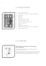
Page 4: ...g F 2 Ganzmetall Thermometer mit Tauchhülse im Kugelhahn integriert Vorlauf F 1 Vorlauf vom Wärmeerzeuger Kessel 2 3 AUSS TATTUNG 2 4 FUN K TI ON Rücklaufanhebung von Festbrennstoffkesseln Holzfeuerungsanlagen Kamin und Ofenheizungen Mit Hilfe der Rücklaufanhebung wird eine Unterschreitung des Taupunktes und damit die Kesselversottung verhindert Die Rücklaufanhebung wird an einen Pufferspeicher an...

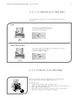
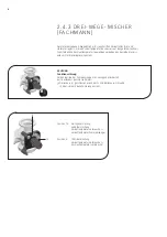
Page 5: ... machen Sie die Anlage drucklos 3 Ziehen Sie den Stellmotor vom Mischer ab 4 Drehen Sie die Nase des Mischerkükens auf Position VL zu so dass der Mischer verschlossen ist Der Mischer ist nun tropfdicht verschlossen Die Pumpengruppe ist im Mischer C 4 mit einer aufstellbaren Schwerkraftbremse ausgestattet Betrieb Im Betrieb muss die Markierung auf Z zeigen Die Schwerkraftbremse ist geschlossen Durc...

Page 6: ...rs wird am Stellmotorregler eingestellt 10 0 ACHTUNG Funktionsstörung Für den Betrieb der Pumpengruppe ist es zwingend erforderlich dass der Bypass geschlossen bleibt Der Bypass ist geschlossen wenn der Schlitz der Bypass Schraube in einer Linie mit den Markierungen steht Position 10 Durchgangsstellung keine Beimischung Vorlauftemperatur Verbraucher Vorlauftemperatur Wärmeerzeuger Position 0 100 B...

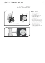
Page 7: ...lmotor auf Handbetrieb 3 Drehen Sie den Stellknopf des Stellmotors nach links siehe Abbildung links 4 Rasten Sie den Stellmotor erst nach Montage der inneren Dämmelemente siehe Seite 14 auf den Stellknopf des Mischers auf 5 Verbinden Sie den Vorlauffühler und den Stellmotor miteinander 6 Stellen Sie am Stellmotor den Automatikbetrieb und die gewünschte Vorlauftemperatur ein Verdrehsicherung 0 Wahl...

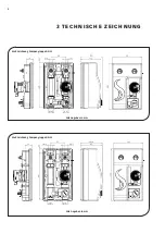
Page 8: ...8 Maßzeichnung Pumpengruppe DN 25 Maßzeichnung Pumpengruppe DN 32 3 T ECH N ISCH E ZE ICH NUNG Alle Angaben in mm Alle Angaben in mm ...

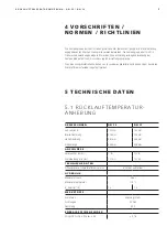
Page 9: ... bestehen aus recycelbaren Materialien und können dem normalen Wertstoffkreislauf wieder zugeführt werden 5 TE CH N ISCH E DATE N AB MESSUNGEN DN 25 DN 32 Achsabstand 125 mm 125 mm Breite Dämmung 250 mm 250 mm Höhe Dämmung 385 mm 443 mm Einbaulänge 340 mm 398 mm AN SCHLÜSSE Verbraucher VL RL 1 IG 1 IG Wärmeerzeuger VL RL 1 AG 1 AG TE CH NISCHE DATEN Öffnungsdruck Schwerkraftbremse C 4 4 9 mbar auf...

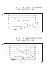
Page 10: ...1 0 Druck mbar Druck kPa Volumenstrom l h 5 2 DI FF ERENZDRUC K DI AGRAMM P UMPENGRUPPE DN 25 5 3 DI FF ERENZDRUC K DI AGRAMM P UMPENGRUPPE DN 32 Druck mbar Druck kPa Volumenstrom l h ...

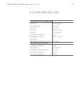
Page 11: ...P42 gem EN 60529 Schutzklasse I gem EN 60730 1 Zulässige Umgebungstemperatur 0 50 C Zulässige relative Feuchtigkeit max 85 rH bei 25 C Programmklasse A Datenaufbewahrung ohne Stromversorgung min 10 Jahre TE CH NISCHE DATEN F ÜHLER Zulässiger Temperaturfühler Typ Pt1000 Fühlerwiderstand 1078 Ohm bei 20 C Verwendungstemperaturbereich Fühler 25 150 C Min Leiterquerschnitt für Fühler 0 3 mm Max Länge ...

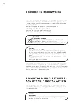
Page 12: ...hteigenschaften verloren gehen Für Schäden die durch derartig beschädigte Dichtungen entstehen übernehmen wir weder eine Haftung noch leisten wir Garantie ersatz Vermeiden Sie unbedingt dass EPDM mit mineralölhaltigen Substanzen in Kontakt kommt Verwenden Sie geeignetes Silikonspray 7 MONTAGE UND BE TRIE B S ANL EITUN G INSTA LLATION ACHTUNG Sachschaden Um Schäden an der Anlage zu verhindern muss ...

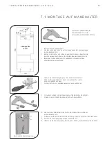
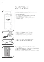
Page 13: ...ben an der Wand 5 Nehmen Sie die Pumpengruppe aus der hinteren Dämmschale 6 Ziehen Sie die Clip Federn mit einem Schraubendreher seitlich aus den Kugelhähnen heraus 7 Entnehmen Sie die Schallentkopplungen aus den Kugelhähnen 8 Schrauben Sie beide Schallentkopplungen auf die Bolzen des Wandhalters 9 Schieben Sie die Clip Federn wieder seitlich auf die Kugelhähne Rückansicht hintere Dämmschale 10 St...

Page 14: ...r hinteren Dämmschale 6 Ziehen Sie die Clip Federn mit einem Schraubendreher seitlich aus den Kugelhähnen heraus 7 Entnehmen Sie die Schallentkopplungen aus den Kugelhähnen 8 Schrauben Sie beide Schallentkopplungen auf die Stockschrauben 9 Schieben Sie die Clip Federn wieder seitlich auf die Kugelhähne Rückansicht hintere Dämmschale 10 Stanzen Sie die zwei vorgefrästen Löcher der hinteren Dämmscha...

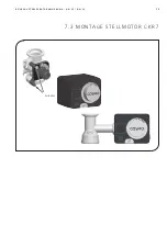
Page 15: ...1 5 R Ü C K L A U F T E M P E R A T U R A N H E B U N G D N 2 5 D N 3 2 Rastbolzen 7 3 M ON TAGE S TELLM OTOR CKR7 ...

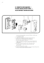
Page 16: ...er Pumpengruppe 6 Montieren Sie den Stellmotor 4 siehe Seite 7 7 Verlegen Sie die Kabel des Stellmotors der Pumpe und des Temperaturfühlers im Kabelkanal der hinteren Dämmschale 1 Der Temperaturfühler befindet sich im Vorlaufkugelhahn 8 Montieren Sie das obere Dämmelement 5 der Pumpengruppe und die Thermometergriffe 6 Drücken Sie die hintere Dämmschale 1 dafür leicht nach hinten 9 Montieren Sie di...

Page 17: ...verbindung zwischen Pumpengruppe und Heizungsanlage 3 Ziehen Sie die Clip Federn mit einem Schraubendreher seitlich heraus um die Pumpengruppe von der Wandhalterung oder den Stockschrauben abzunehmen 4 Ziehen Sie die Pumpengruppe nach vorn ab 8 1 ANSC HLUSS S C HEMA CO S MO Pufferspeicher Typ CPS MAG wasserführender Kaminofen oder Holzkessel KW ...

Page 18: ...1 8 8 3 INB ETRI EB NAHM E STE LLM OTOR C K R7 8 3 1 EI NSTELLUN G RÜC K LAUF H OCHHALTUNG 5 s 8 3 2 EI NSTELLUN G DER TE MPERATUREN ...

Page 19: ...ll zu behandeln ist sondern an einer Annahmestelle für das Recycling von eletrischen und elektronischen Geräten abgegeben werden muss Durch Ihren Beitrag zum korrekten Entsorgen dieses Produkts schützen Sie die Umwelt und die Gesundheit Ihrer Mitmenschen Umwelt und Gesundheit werden durch falsches Entsorgen gefährdet Materialrecycling hilft den Verbrauch von Rohstoffen zu verringern Weitere Inform...

Page 20: ...Mischerdrehknopf für Stellmotor CKR7 CWR6 CKR6 16 YCOQ00016 Dämmung f Pumpengruppe DN 25 mit CKR6 CWR6 CKR7 Komplettsatz 205 YCOQ00205 Stellmotor CKR7 6 Nm 230 V 120 s 90 inkl Drehknopf und Schraube 18 YCOQ00018 Temperaturfühler Pt1000 B G AL 290 mm C Grid SL 45 YCOQ00045 3 Wege T Mischer DN 25 Bypass geschlossen mit Mischerdrehknopf 1 F x 1 AG 48 YCOQ00048 Ersatzteilset für Kugelhahn DN 25 49 YCO...

Page 21: ...290 mm C Grid SL 69 YCOQ00069 COSMO 2 0 Überwurfmutter G2 90 YCOQ00090 Kugelhahn DN 32 2x Stopfen mit Thermometeraufnahme 96 YCOQ00096 Ersatzteilset für Kugelhahn DN 32 97 YCOQ00097 Ersatzteilset 3 Wege T Mischer DN 32 98 YCOQ00098 Dämmung für PG Rücklaufanhebung DN 32 Komplettsatz 99 YCOQ00099 3 Wege T Mischer DN 32 Bypass geschlossen mit Mischerdrehknopf 1 F x 1 AG 109 YCOQ00202 COSMO 2 0 Rückla...

Page 22: ...2 2 10 PFLE GE H IN W E ISE Es sind keine Pflegehinweise für dieses Produkt vorhanden ...

Page 23: ... Ausfu hrungsangaben entsprechen dem Tag der Drucklegung Technische Änderungen sowie Änderungen an Farbe oder Form der abgebildeten Produkte vorbehalten Farbabweichungen sind auch aus drucktech nischen Gru nden nicht auszuschließen Modell und Produktanspru che können nicht geltend gemacht werden Im Rahmen der zur Zeit gu ltigen gesetzlichen Bestimmungen des Kaufvertragsrechts BGB hinsichtlich Mäng...

Page 24: ......

Page 25: ...G U T E S K L I M A B E S S E R L E B E N INSTALLATION AND OPERATION INSTRUCTIONS RETURN TEMPERATURE MAINTENANCE DN 25 DN 32 INSTRUCTIONS FOR USE RETURN TEMPERATURE MAINTENANCE DN 25 DN 32 ...

Page 26: ...n a wall bracket 37 7 2 Installation on stair bolts 38 7 3 Assembly actuator CKR7 39 8 Commissioning Function test Decommissioning 40 8 1 Connection scheme 41 8 2 Deinstallation 41 8 3 Commissioning actuator CKR7 42 8 3 1 Adjustment return temperature maintenance 42 8 3 2 Adjustment of temperatures 42 8 3 3 Change of basic settings 43 8 4 Disposal 43 9 Maintenance 44 9 1 Spare parts 44 9 1 1 Pump ...

Page 27: ...her components of the installation such as the pump the controller or the distribution manifold please observe the separate instructions The chapters called specialist are intended for specialists only 2 2 PRODUC T DES C RI PTI ON The pump group is a premounted group of fittings for the return temperature maintenance of the boiler The actuator of the mixing valve is equipped with a constant temper...

Page 28: ...tal thermometer with immersion sleeve integrated in the ball valve flow F 1 Flow from the heat generator boiler 2 3 E QUI PMENT 2 4 FUN C TI ON Return temperature maintenance of solid fuel boilers wood fired heating systems and stove heating systems The return temperature maintenance prevents the temperature in the boiler from falling under the dew point thus reducing the contamination of the boil...

Page 29: ...stallation 3 Remove the actuator from the mixing valve 4 Turn the nose of the valve cock into position VL zu flow closed to close the mixing valve The mixing valve is now closed and drop tight The pump group is equipped with a check valve in the mixing valve C 4 The check valve can be opened manually Operation During operation the marking must be directed to Z The check valve is closed Flow only i...

Page 30: ...rature according to the specifications of the boiler manufacturer is set at the actuator 10 0 ATTENTION Malfunction It is mandatory for the operation of the pump group that the bypass remains closed The bypass is closed if the slot of the bypass screw is in the same line as the markings Position 10 Passage no mixing flow temperature consumer flow temperature heat generator Position 0 100 mixing fl...

Page 31: ...manual mode by turning the selector switch 3 Turn the adjusting knob of the actuator to the left see figure on the left 4 Mount the inner insulation elements see page 14 before putting the actuator on the adjusting knob of the mixing valve 5 Connect the flow sensor with the actuator 6 Set the automatic operation mode and the desired flow temperature at the actuator Rotation lock 0 Selector switch ...

Page 32: ...3 2 Dimensional drawing pump group DN 25 Dimensional drawing pump group DN 32 3 T ECH N ICA L D R AW IN G All dimensions in mm All dimensions in mm ...

Page 33: ... be disposed of with recyclable materials 5 TE CH N ICA L DATA DI MENSIONS DN 25 DN 32 Centre distance 125 mm 125 mm Width insulation 250 mm 250 mm Height insulation 385 mm 443 mm Installation length 340 mm 398 mm CO N NECTIONS Consumer flow return 1 int thread 1 int thread Heat generator flow return 1 ext thread 1 ext thread TE CH NICAL DATA Opening pressure check valve C 4 4 9 mbars can be opene...

Page 34: ...3 4 Pressure mbar Pressure kPa Flow rate l h 5 2 DI FF ERENTI AL PRESS URE D IA GRAM PUM P GROUP DN 25 5 3 DI FF ERENTI AL PRESS URE D IA GRAM PUM P GROUP DN 32 Pressure mbar Pressure kPa Flow rate l h ...

Page 35: ...o EN 60529 Protection class I acc to EN 60730 1 Admissible ambient temperature 0 50 C Admissible relative humidity max 85 rH at 25 C Programme class A Data storage without power supply min 10 years TE CH NICAL DATA SENSOR Admissible temperature sensor type Pt1000 Sensor resistance 1078 ohms at 20 C Operating temperature range sensor 25 150 C Min conductor cross section for sensor 0 3 mm Max length...

Page 36: ...ade of EPDM whereby the sealant properties are lost We do not assume liability nor provide warranty for damage to property resulting from sealants damaged in this way It is imperative to prevent the EPDM sealing elements from making contact with substances containing mineral oils Use a suitable silicone spray 7 INSTR UCTIONS FOR USE INSTA LLATION ATTENTION Damage to property The location of instal...

Page 37: ...using appropriate screws and the washers 5 Take the pump group out of the insulating back shell 6 Pull out the clip springs laterally from the ball valves with a screwdriver 7 Remove the acoustic decoupling elements from the ball valves 8 Screw both acoustic decoupling elements on the bolts of the wall bracket 9 Push the clip springs laterally on the ball valves Rear view insulating back shell 10 ...

Page 38: ...ump group out of the insulating back shell 6 Pull out the clip springs laterally from the ball valves with a screwdriver 7 Remove the acoustic decoupling elements from the ball valves 8 Screw both acoustic decoupling elements on the stair bolts 9 Push the clip springs laterally on the ball valves Rear view insulating back shell 10 Punch out the two pre milled holes of the insulating back shell see...

Page 39: ...3 9 R E T U R N T E M P E R A T U R E M A I N T E N A N C E D N 2 5 D N 3 2 Stop bolts 7 3 ASS EMB LY AC TUATOR C KR7 ...

Page 40: ... of the pump group 6 Mount the actuator 4 see page 7 7 Run the cables of the actuator of the pump and of the temperature sensor in the cable channel of the insulating back shell 1 The temperature sensor is situated in the flow ball valve 8 Mount the upper insulation element 5 of the pump group and the thermometer handles 6 Push the insulating back shell 1 slightly backward 9 Mount the insulating f...

Page 41: ...pe connection between the pump group and the heating installation 3 To remove the pump group from the wall bracket or the stair bolts pull out the clip springs laterally by using a screwdriver 4 Remove the pump group by pulling it forward 8 1 C ON N EC TI ON S C HEME CO S MO buffer tank type CPS DET water carrying fireplace or wood boiler Cold water ...

Page 42: ...4 2 8 3 COM MI SS I ON I N G A CTUATOR C K R7 8 3 1 ADJUSTM EN T RETURN TE MPERATURE M AI NTEN ANC E 5 s 8 3 2 ADJUSTM EN T OF TE MPERATURES ...

Page 43: ...be treated as normal domestic waste but must be disposed at a collection point for the recycling of electrical and electronic devices With your contribution to the correct disposal of this product you protect the environment and the health of others Incorrect disposal affects the environment and health Recycling materials helps to reduce the consumption of resources You can receive further informa...

Page 44: ...KR6 16 YCOQ00016 Insulation for pump group DN 25 with CKR6 CWR6 CKR7 complete set 205 YCOQ00205 Actuator CKR7 6 Nm 230 V 120 s 90 including rotary knob and screw 18 YCOQ00018 Temperature sensor Pt1000 B G cable length 290 mm C Grid SL 45 YCOQ00045 3 way T mixing valve DN 25 bypass closed with mixing valve rotary knob 1 F x 1 ext thread 48 YCOQ00048 Spare parts set for ball valve DN 25 49 YCOQ00049...

Page 45: ...069 COSMO 2 0 union nut G2 90 YCOQ00090 Ball valve DN 32 2x plug with device for thermometer 96 YCOQ00096 Spare parts set for ball valve DN 32 97 YCOQ00097 Spare parts set for 3 way T mixing valve DN 32 98 YCOQ00098 Insulation for return temperature maintenance pump group DN 32 complete set 99 YCOQ00099 3 way T mixing valve DN 32 bypass closed with mixing valve rotary knob 1 F x 1 ext thread 109 Y...

Page 46: ...4 6 10 CA R E INSTR UCTIONS There are no care instructions for this product ...

Page 47: ...product and design related information are valid at the date of printing We reserve the right to make technical chan ges as well as changes in colour and form of the illustrated products without notice Colours may differ due to printing process Model and product claims cannot be asserted Within the scope of the currently valid legal provisions of the purchase contract law German Civil Code BGB in ...

Page 48: ...C O S M O GMBH Brandstücken 31 22549 Hamburg i n f o c o s m o i n f o d e w w w c o s m o i n f o d e G U T E S K L I M A B E S S E R L E B E N ...

Reviews: