Coustic XM6, Owner'S Manual
The Coustic XM6 Owner's Manual is available for free download on 88.208.23.73:8080, providing detailed instructions on how to maximize your product's potential. This comprehensive manual covers every aspect of operating the Coustic XM6, ensuring a seamless user experience. Get the most out of your product with our easy-to-access manual download.
Share
Download


Reviews:
No comments
Related manuals for XM6
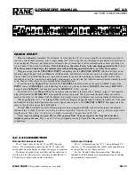
AC 22
Brand: Rane Pages: 4
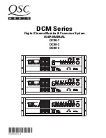
DCM-1
Brand: QSC Pages: 36
AD 22B
Brand: Rane Pages: 6
AC 23
Brand: Rane Pages: 18
LXR-7A
Brand: Legacy Pages: 12
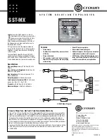
SST-MX
Brand: Crown Pages: 1
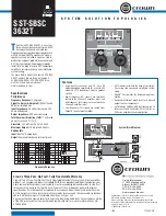
SST-SBSC 3632T
Brand: Crown Pages: 1

F.A.C.T. F-3
Brand: XETEC Pages: 6
TSD-HF11
Brand: Atlas Pages: 16
S Class
Brand: Samson Pages: 20
ACX-23S
Brand: DAPAudio Pages: 13
HFEQ
Brand: Hifonics Pages: 10
CX-2213
Brand: Nady Audio Pages: 10
SNAXO 362BMR
Brand: NAIM Pages: 24
KLIMAX AKTIV
Brand: Linn Pages: 23
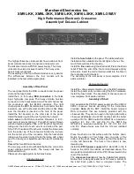
XM16L-3KK
Brand: Marchand Electronics Pages: 12
FDS 310
Brand: BSS Audio Pages: 40
SUPER-X PRO CX2310
Brand: Behringer Pages: 13


