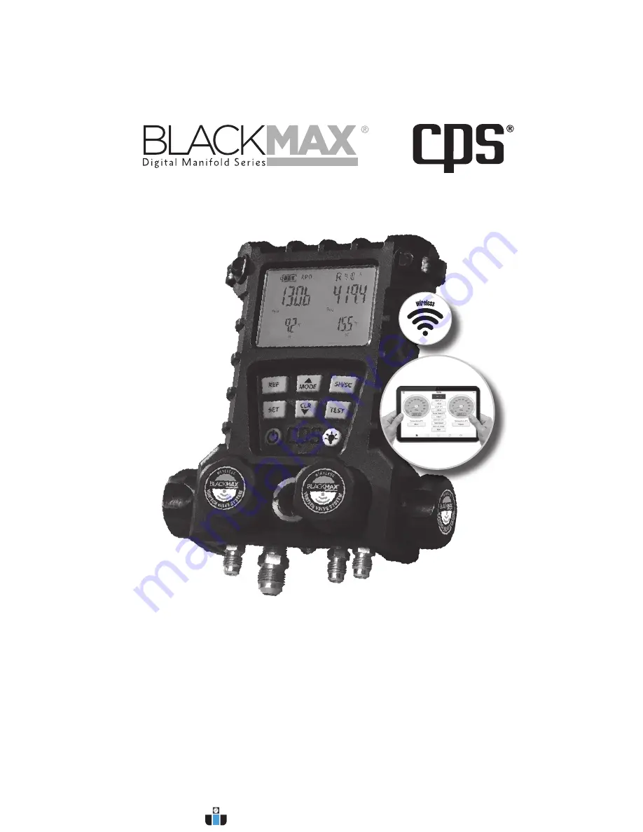
background image

OWNER’S MANUAL 

(English) 

(Software Version 1.1 or Higher with CPS

®

 Link

 App)

2 Valve Series:  MD50W, MD50WHE, MD50WVHE 

4 Valve Series:  MD100W, MD100WHE, MD100WVHE

WIRELESS SERIES

For use with free BLACKMAX

® 

app featuring CPS

®

Link

™  

US Patent No. 9,043,161.  For Android or iOS mobile devices.

www.calcert.com

sales@calcert.com

1.888.610.7664

0

5

10

15

20

25

30

Summary of Contents for BlackMax MD100W

Page 1: ...p 2 Valve Series MD50W MD50WHE MD50WVHE 4 Valve Series MD100W MD100WHE MD100WVHE WIRELESS SERIES For use with free BLACKMAX app featuring CPS Link US Patent No 9 043 161 For Android or iOS mobile devices www calcert com sales calcert com 1 888 610 7664 0 5 10 15 20 25 30 ...

Page 2: ...ix E Cleaning Sensor in MDXVG Vacuum Gauge 26 Appendix F Limited Warranty 27 Appendix G Refrigerants Stored in MD50W and MD100W series 27 Appendix H Error Indicator Screens 28 CONTENTS OVERVIEW New Wireless BLACKMAX digital manifolds can be used as conventional stand alone manifolds or can also be used with a free APP allowing a mobile device running on iOS or Android platforms to communicate dire...

Page 3: ...URER S TEST PROCEDURES WHEN SERVICING THOSE SPECIFIC TYPES OF EQUIPMENT WARNING Remove all hoses with care as they may contain liquid refrigerant under pressure Contact with refrigerant may cause frostbite or other related injuries Wear proper personal protective equipment such as safety goggles and gloves When disconnecting any hose please use extreme caution WARNING Avoid breathing refrigerant v...

Page 4: ...refrigerant flow 12 VACUUM VALVE MD100 Series Only Controls flow through LEFT MIDDLE 3 8 SAE PORT 13 LOW SIDE VALVE Controls flow to LEFT SIDE SAE Port 14 CENTER PORT MD50W Series Only A SAE Male T port used as common connection to vacuum pump recovery unit or refrigerant supply tank The addition of a SAE Male T fitting with valve core allows for a dual hook up between vacuum pump and refrigerant ...

Page 5: ...uum Valve 13 Low Side Valve 1 On Off 2 Set 3 Refrigerant 4 Mode 5 Superheat Subcool 21 Connection Points For Thermistor Sensors 18 Swivel Hook 19 Battery Compartment 20 Hose Hangers 15 9V DC Charger Port 16 Vacuum Gauge Accessory Port 22 SAE Hose Connection Ports 22 Storage Posts 4 Valve Manifold Back www calcert com sales calcert com 1 888 610 7664 0 5 10 15 20 25 30 ...

Page 6: ...ee Connector Included with MDXVG Kit MDXCP Thermistor Sensor with 6 Ft lead for taking Superheat and Subcool true temperatures on pipes Vacuum Gauge Accessory Kit MDXVG U S Plug 5 Ft Cord UK Ireland Singapore Hong Kong Plug Euro Plug Australia New Zealand China Plug Universal Charger MDXBK 4 AA Rechargeable NiMH Batteries Thermistor Sensor MDXCP Soft Case MDXSC Included 2 www calcert com sales cal...

Page 7: ...nk icon from your mobile device 5 The application will appear on your mobile device screen in landscape mode 6 Select one BLACKMAX Wireless Digital Manifold to operate 7 Review and adhere to all safety instructions 8 Connect the BLACKMAX manifold to an AC system see pages 24 26 9 You are now ready to work Indicates wireless manifold has been detected If you plan to use the wireless manifold withou...

Page 8: ...Current Refrigerant Home Screen Settings Data Logging Vacuum Hold Presure Hold Working Temperature s CHANGE OR CONFIRM SETTINGS High Side Low Side Touch arrows to toggle between Home Screens View 1 Or View 2 View 1 View 2 OR Touch icons here to select any of these functions www calcert com sales calcert com 1 888 610 7664 0 5 10 15 20 25 30 ...

Page 9: ...pecially if manifold has been dropped or pressurized beyond 800 psig 55 Bar BLACKMAX APP SETTINGS SCREEN Select One Change Language Zero Offset Target Superheat Change Units Settings www calcert com sales calcert com 1 888 610 7664 0 5 10 15 20 25 30 ...

Page 10: ...tive refrigerant Note Refrigerant selected will become the default but not affect FAVORITE FIVE Changing FAVORITE FIVE refrigerants permanently must be done using the manifold See page 21 for more information www calcert com sales calcert com 1 888 610 7664 0 5 10 15 20 25 30 ...

Page 11: ... Digital Manifold initiate vacuum to enable test Note See Appendix E for cleaning the sensor 2 Touch Start or Stop at any time 3 Default duration 5 minutes Max time 100 mins 4 You may navigate to other screens while this test runs Vacuum Hold Test TESTING Pressure Hold or Vacuum Hold gray line is starting point gray line is starting point Final graph will show initial current and final pressures F...

Page 12: ...nifold will record values 3 View maximum time remaining 4 Start Stop logging at any time or let system run until no more Manifold memory All stored files have option of showing Geolocation Delete View Or Export Logs stored in mobile device Manifold Logs 1 Shows logs stored in manifold 2 Can only erase entire memory 3 Download any file to mobile device Maximum time remaining Touch to select interva...

Page 13: ...al from APP HELP Select for general description of any item 1 General 2 Home 3 Pressure Hold 4 Vacuum Hold 5 Data Logging 6 Settings 7 Side Menu Video Watch instructional videos on how to use this app www calcert com sales calcert com 1 888 610 7664 0 5 10 15 20 25 30 ...

Page 14: ...gion 8 The next screen will be the MAIN screen FIG 1 showing default status for the following Battery charge status APO On or Off High and low side working pressures High and low side temperatures Current working refrigerant QUICK START INSTRUCTIONS WIRELESS DIGITAL MANIFOLD If your mobile device is NOT available Wireless BLACKMAX Digital Manifolds may also be operated as stand alone devices Simpl...

Page 15: ...eat Sub Cool Screen Sub Cool Super Heat FIG 3 5 Note In this mode and to prevent errors refrigerant cannot be changed using the REF key Press CLR to return to Main Screen FIG 1 from this view Thermistor Sensors The enclosed clamps can be used to take temperatures of pipes or other round surfaces within its jaw range 1 8 to 1 1 8 This greatly improves the calculation of Superheat and Subcool temper...

Page 16: ...ss than 1 oz year In practice there should be no pressure hold detected if the system is deemed leak proof enough to add refrigerant Large leaks should be found before adding refrigerant Low cost tracer gas mixtures such as 95 N2 and 5 H2 are popular and can be sensed by a CPS E_MOS leak detector 1 At Main Screen FIG 1 press TEST The Test Pressure Set Screen will appear FIG 5 Note The MDXVG Vacuum...

Page 17: ... left display FIG 7 Current system pressure is shown in upper right display Timer lower left display decrements and when at zero a bell will sound indicating test completion and Start Vs Final Pressures will be displayed FIG 8 to determine if system leaks VACUUM HOLD TEST Normally systems with vacuum levels within 250 500 microns are deemed as having a good seal and are ready for charging As with ...

Page 18: ...3 8 Use UP DOWN ARROWS to adjust test duration in 5 minutes increments minimum time is pre programmed at 5 minutes A Press SET to store Vacuum Test duration time Vacuum Hold Test Screen FIG 14 will now be displayed APO Vac FIG 12 Test Vacuum Set Screen hh mm Vac APO Vacuum Hold Test Time Set Screen FIG 13 Set test duration adjust in 5 minute increments NOTE The Vacuum Reading in the upper Left dis...

Page 19: ...nable determination of any vacuum loss over a set period of time Inactive Current Vacuum Level Leak test duration FIG 14 D Press CLR to return to Main Screen FIG 1 NOTE If it is required to rerun the vacuum pump after STEP 3 disconnect and reconnect the MDXVG to reset it in the vacrometer mode Vacuum Display Screen Current System Vacuum Level Desired Test Level Timer counts backwards FIG 15 PROGRA...

Page 20: ...G 17 3 The Initial Refrigerant blinking in upper right should be R 11 and Counter Lower Right should start at 000 4 Use UP DOWN ARROWS to scroll through 93 refrigerants Press and hold either arrow to scroll through refrigerants progressively faster Release to stop scrolling Last refrigerant displayed will blink There are 2 major options In each a blinking symbol represents a choice the user can ma...

Page 21: ...enu and go to the next Temperature Units Screen press SET or 8 To return to Main Screen FIG 1 press and hold CLR after step 6 9 If all 5 refrigerants are changed manifold automatically advances to next menu without having to press SET Main Screen FIG 1 can then be accessed by pressing and holding CLR PROGRAMMING SETTING PRESSURE UNITS PSIG KGCM2 KPA BAR MPA 1 At Main Screen FIG 1 press and hold MO...

Page 22: ...ing SET Menu In either case units become current units and manifold returns to Main Screen FIG 1 Psig mic APO F Units Summary Screen Blinking symbols indicate Pressure Temperature and Vacuum Units chosen in previous steps FIG 21 APO When APO is ON and there has been no user activity usually 10 15 minutes manifolds turn OFF to conserve battery power About 1 minute before turning OFF an alarm will s...

Page 23: ... Connect hose from to open port on the tee C to Refrigerant Recovery Unit inlet port 2 Connect hose from port 4 to Refrigerant Recovery unit inlet port 3 Start Recovery Unit 3 Open low side valve A 4 Open low side valve A 4 Open high side valve B 5 Open high side valve B 5 Start Recovery Unit 6 Complete refrigerant recovery process 6 Open valve D 7 Disconnect manifold from system 7 Complete refrig...

Page 24: ...storHighSideChargingProcedure EVACUATING PROCEDURES CHARGING PROCEDURE LOW SIDE MD50W 2 Valve Manifold FIG 24 MD100W 4 Valve Manifold FIG 25 1 The following instructions are to add charge to a pressurized system known as topping off 2 Connect Low A and High B Service hoses to service ports E and D All valves should be closed 2 Connect Low 1 and High 2 Service hoses to service ports L and H 3 Conne...

Page 25: ...accuracy 10 microns requires MDXVG accessory SH SC and saturation temperature accuracy 0 5 F 0 3 C Instrument working temperature 4 0 F to 122 F 20 C to 50 C Instrument working RH range 0 to 100 non condensing Total number of stored refrigerants 93 APO Automatic Power Off 10 minutes Can be disabled by user MD100W size L x H x W 8 1 x 3 5 x 7 0 20 5 cm x 8 9 cm x 17 8cm MD50W size L x H x W 8 1 x 2...

Page 26: ... first time turn manifold off and connect one end of charger to Manifold 9V DC plug FIG 26 and the other end to an appropriate wall outlet socket Charge NiMH batteries for 2 hours The Battery Symbol on the display will blink during charging MD50W and MD100W manifold series can be used while charging the batteries but charging time will be considerably extended The preferred way to use the Rapid Ch...

Page 27: ...ACKMAXproducts CPShasthesolerighttodetermine ifaclaimisvalidandifcompensationisjustified THEFOREGOINGWARRANTYISINLIEUOFALLOTHEREXPRESSWARRANTIES TOTHEEXTENTALLOWED BY LAW ANY IMPLIED WARRANTIES OF MERCHANTABILITY OR FITNESS FOR A PARTICULAR PURPOSE ARE LIMITED TO THE DURATION OF THE LIMITED PRODUCT WARRANTY IN NO CASE SHALL CPS PRODUCTSINC HAVEANYLIABILITYFORSPECIAL INCIDENTALORCONSEQUENTIALDAMAGE...

Page 28: ...ensor connected to that port is short circuited Replace sensor with CPS model number TMX3C Err Upper Left Display Appears in upper left display when T function is selected and one or both thermistor sensors are defective as indicated by oP or SP indicators mentioned above Err Lower Left Display Appears in display areas reserved for temperature readings when user tries to read saturation temperatur...

Reviews: