background image

Summary of Contents for 113.23301

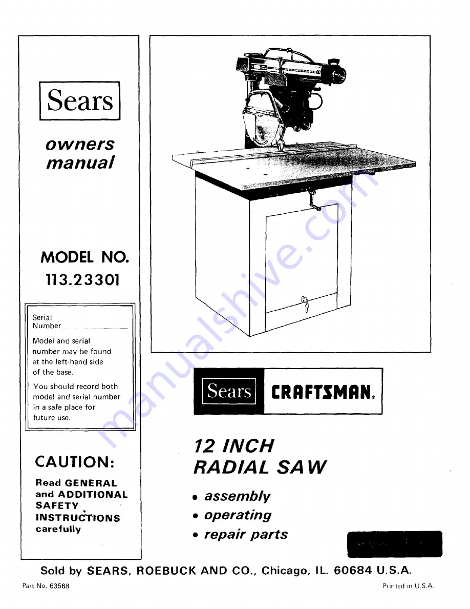
Page 1: ... side of the base You should record both model and serial number in a safe place for future use CAUTION Read GENERAL and ADDITIONAL SAFETY b INSTRUCTIONS carefully RRFTSMRNo 12 INCH RADIAL SAW assembly operating repair parts Sold by SEARS ROEBUCK AND CO Chicago IL 60684 U S A Part No 63568 Printed ill U S A ...

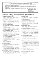
Page 2: ...AR PROPER APPAREL Do not wear loose clothing gloves neckties or jewelry rings wrist watches to get caught in moving parts Nonslip footwear is recommended Wear protective 21 hair covering to contain long hair Roll long sleeves above the el bow 12 USE SAFETY GOGGLES Head Protection 22 Wear Safety goggles must comply with ANS Z87 1 at all times Also use face or dust mask if cutting operation is dusty...

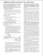
Page 3: ...el locks clamps are tight A large proportion of saw accidents is caused by use of the wrong type blade dull badly set improperly sharpened cutting tools by gum or resin adhering to cutting tools and by sawblade misalignment with the fence Such conditions can cause the material to stick jam stall the saw or KICKBACK A KICKBACK occurs when a part or all of the workpiece is thrown back violently towa...

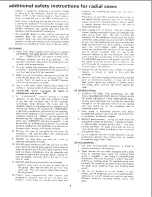
Page 4: ...from that same side This wilt require added table support for long pieces 12 Plastic and composition like styrene and hardboard materials may be cut on your saw However since these are usually quite hard arrd slippery the antikickback pawls may not stop a kickback Therefore rip with the firfished side down next to the table and be especially attentive to following proper set up and cutting procedu...

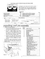
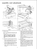
Page 5: ... received by the purchaser These loose parts are shown in figure 2 and listed in the Table of Loose Parts below c Separate all loose parts from packaging materials and check each item with figure 2 and Table of Loose Parts making sure all items are accounted for before discarding any packing material If any parts are missing Do Not attempt to assemble the Radial Saw plug in the power cord or turn ...

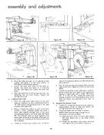
Page 6: ...Iockwasher LOCKWASHER FLAT WASHER 13 32 IN 3 8 In Figure 6 d Grasp the carriage with both hands figure 4 and carefully start the carriage bearings onto the tracks on the radial arm Be sure to hold the assembly parallel to the arm as it is carefully slipped into position until all four bearings are on the tracks in order to prevent excessive strain on the bearings and tracks e Install and tighten t...

Page 7: ...dle d Tilt the motor to the left as shown in figure 8 The latch pin will drop into a notch when the motor and carriage assembly are rotated to the 45 position e Remove and discard two 5 16 inch hex head screws and shipping spacers See figure 8 f Lift the latch pin handle and rotate motor and carriage assembly back to a horizontal position Tighten the bevel lock knob Installing Remaining Loose Part...

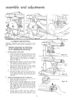
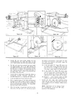
Page 8: ...ate the arbor wrench dowr_ward to loosen the shaft nut The motor shaft has left hand threads See figure 12 d Remove the shaft nut and outer collar e Grasp the saw blade slide it off the shaft and out of the guard See figure 13 Remove the inner collar and guard Place the guard and blade out of work area Adjusting Table Supports Parallel To Radial Arm a Loosen the bevel lock knob and lift up on the ...

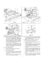
Page 9: ...n setting of the motor until all table supports have been adjusted g Remove the arbor wrench and position the motor until end of shaft is directly over the rear position of table support No 2 See figure 18 With the attaching screw hand tight tap the rear of No 2 table support upward or downward until the end of motor shaft just touches the arbor wrench held between the end of motor shaft and top o...

Page 10: ...holes in the front table See figure 25 and through holes in table supports One screw near the center of the table is threaded into the U clip nut mounted on the forward end of the No 2 support c Install six 1 4 inch lock washers and 1 4 20 hex 4 nuts on all screws except the one that threads into the U clip nut d Run all nuts up onto the screws firmly but not tight at this time Tighten the screw i...

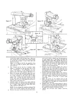
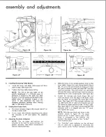
Page 11: ...e as shown in figure 30 and the long leg of the square just contacting a tooth of the saw blade Position A figure 30 Mark this tooth with a soft pencil When the carriage is moved back and forth on the radial arm the saw tooth A should just touch the square at all positions If saw tooth A does not touch the square at all points make the following adjustments 1 If the saw tooth A figure 30 moves int...

Page 12: ...are intended to be used for quick settings For greater accuracy take direct measurement between blade and fence With the fence in its normal position next to the front table loosen the yoke clamp handle figure 36 lift up on the swivel latch pin knob and rotate the yoke as shown to index the yoke 90 from the cross cut position This will locate the saw blade between the motor and the fence Lock the ...

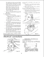
Page 13: ... d Place the outer collar on the shaft with the flat side facing the saw blade Start the shaft nut left hand threads on the shaft and tighten the shaft nut securely See figure 42 e Rotate the guard until the knob is in front and tighten the knob to secure the guard in position This lower retractable guard is designed to provide additional protection to the operator in an axia direction to he sawbl...

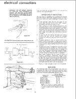
Page 14: ...r circuit breakers may result if motor is overloaded or if the motor circuit is fused with other than those recommended Do not use a fuse of greater capacity without consulting the power company 5 Although the motor is designed for operation on the voltage and frequency specified on motor nameplate normal loads will be handled safely on voltages not more than 10 above or below the nameplate voltag...

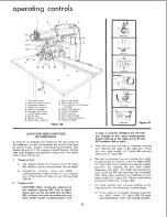
Page 15: ...ne complete turn of the handle will raise or lower the saw blade 1 8 inch 2 Angle of Cut CAUTION When moving the radial arm in any direction beyond 45 left or right always pull out the arm latch lever 1 figure 46 or loosen the lever by rotating the arm latch handle knob counterclockwise until C it stops to prevent damaging the arm lock pin Damage of this nature would prevent proper indexing of the...

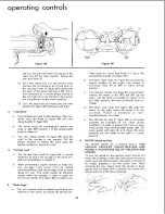
Page 16: ...b should be tightened except when the operator is ready to grasp the bevel index handle 14 figure 46 and make a cut Blade Angle a The two controls used in angular positioning and indexing of the motor to provide the desired saw 8 16 b d blade angle are bevel lock knob 12 figure 46 and latch pin handle 15 figure 46 The bevel index scale 11 figure 46 indicates the angular position of the motor with ...

Page 17: ...imately 1 32 inch d Push in the on off switch to stop the motor and allow the blade to come to a complete stop e f Place the workpiece to be ripped in the position shown in figure 51 Loosen the guard clamp knob figure 50 and rotate the guard so that it just clears the workpiece figure 51 Tighten the guard clamp knob g Loosen the wing screw figure 49 and with tab C position the anti kickback and sp...

Page 18: ...m saw blade 7 Yoke clamp handle must be in locked position 8 Bevel index knob must be tight 9 Blade should cut into the table or plywood cover not more than 1 32 inch 10 Pull the saw forward just far enough to sever the lumber tt is dangerous if the blade has been pulled too far out beyond the piece being cut When it is returned it can pick up the right hand piece and throw it over the fence 11 Fo...

Page 19: ...de When ripping narrow or short stock always use a push board 7 Saw blade must be parallel to fence to minimize possibility of kickbacks OPERATION No 5 OUT RIPPING AND IN RIPPING 1 Ripping is the process of sawing the workpiece by feeding t into the saw blade when using the fence as a guide and as a positioning device to obtain the desired width of cut See figures 57 through 5g 2 Provide a straigh...

Page 20: ...nd side of radial arm Figure 58 Figure 59 OPERATION No 6 BEVEL RIPPING Bevel ripping is either in ripping or out ripping as described above except the saw blade is tilted out of perpendicular to the saw table surface Figure 59 shows a typical bevel out ripping operation The radial arm is indexed at 0 and locked the bevel is set to the desired bevel angle and the yoke is positioned for in ripping s...

Page 21: ...e and tightened with medium firmness after the adjustment has been completed This screw applies pressure on the nylon friction plug and provides smoother elevation movement of column tube This set screw should be tightened to provide maximum smoothness of operation Right and left positions are given with operator facing the saw standing in front of saw table b Adjusting Column Tube Key 1 Loosen th...

Page 22: ... radial arm cap and lift out the cap 2 Rotate the arm latch handle figure 63 one quarter turn counterclockwise but do not pull it out 3 Loosen do not remove two 3 8 16 hex head screws figure 62 located inside the column tube 4 Mow radial arm slightly in the proper direction to make saw tooth A figure 63 follow edge of square when the saw blade is moved in and out in a cross cut manner 5 Re tighten...

Page 23: ...e socket head screws are being tightened d Tighten the socket head screws figure 65 and bevel lock knob It may be CARRIAGE COVER LEFT HAND BEARING YOKE CLAMP ASSEMBLY ATTACHNG SCREWS Figure 67 Figure 70 necessary to perform several trial operations before the saw blade remains perfectly square with the table after tightening the four screws 3 After completing this adjustment set the bevel indicato...

Page 24: ...e lock screw See figure 72 Usually rotating the yoke clamp assembly one hole will corect this adjustment However in some extreme cases it may be necessary fo rotate it two holes or more 6 7 8 Install and tighten the lock screw See figure 72 Hold the motor and carriage assembly parallel to radial arm and start the rear bearings onto the tracks Continue to hold the assembly parallel to the tracks un...

Page 25: ... replace the saw blade Avoid the attempted use of severly warped material b Crosscut Not Properly Squared Adjust as described in paragraph Squaring the Crosscut Travel c Radial Arm Not Securely Locked in 0 Position Loosen the arm latch handle and refer to paragraph Precision Indexing d Blade Heels to the Right Refer to paragraph Blade Heels to the Right or Left BOARD BINDS OR PULLS AWAY FROM FENCE...

Page 26: ...wires or circuit too long 3 General overloading of power company s facilities In many sections of the country deman_ for electrical power exceeds the capacity of existing gen erating and distribution systems 1 Low Voltage will not trip relay 2 Starting relay not operating 1 Motor overloaded 2 Improper cooling Air circula tion restricted through motor due to sawdust etc 1 Burned relay contacts due ...

Page 27: ...sc b Check for 0 020 inch clearance between brake shoe and brake disk Clearance is probably less than 0 020 inch 1 2 3 4 5 Use spreader Position the saw for ripping as described in applicable paragraphs under Basic Saw Operations Push wood all the way past saw blade Refer to applicable paragraphs under Basic Saw Operations Use caution Refer to applicable paragraphs under Basic Saw Operations Check...

Page 28: ...eo i0 f I I 37 36 L 35 12 13 14 CRAFTSMAN 12 INCH RADIAL SAW MODEL N0 113 23301 15 16 34 33 21 22 25 24 7 l 0 Figure I ...

Page 29: ...w Mach No 8 32 x 3 8 Type 23 Pan Hd Hook Cord Trim Radial Arm Screw Arm Lock Pin Assy Arm Lock Shaft Assembly Latch Arm Ring Retaining 3 8 Washer Spring Support Spring Arm Latch Cap Trim Lever Arm Latch Washer 1 2 x 1 1 8 x 1 16 Washer Spring Washer 1 2 x 1 x 1 32 Key No 24 25 26 27 28 29 30 31 32 33 34 35 36 37 38 39 40 41 42 43 44 45 Part No 455872 63410 63139 63494 30494 60177 30495 3540 63062 ...

Page 30: ...er 5 16 Screw Mach 5 16 18 x 1 1 2 Hex Hd Knob Assembly Spring Swivel Latch Pin Swivel Latch Bearing Carriage Screw Eccentric Clamp Assembly Yoke Shoe Carriage Lock Screw Mach No 10 32 x 5 8 Type 23 Rd Hd Track Arm Radial Screw 5 16 18 x 1 2 Socket Hd Cap Wrench Hex L 1 4 Across Flats Screw Mach No 6 32 x 7 16 Pan Hd Indicator Rip Scale Knob Carriage Lock Screw Mach No 10 32 x 5 8 Pan Hd Cover Car...

Page 31: ... Lock 1 4 20 Guard Assembly Shoe Clamp Screw 1 4 20 x 1 1 8 FI Hd SI Nut Sq 5 16 18 x 9 16 x 7 32 Guard Assembly Lower Inner Shoe Guide Anti Kickback Screw Wing Key Part No No Description 14 STD 60110E 15 STD 551110i 16 63260 17 63268 18 STD 541231 19 63271 20 60220 21 63270 22 63269 23 63259 24 63258 25 63267 26 60210 Screw No 10 32 x 7 16 Type 23 Pan Hd Lockwasher No 0 Pawl Assembly Anti Kickbac...

Page 32: ...123 4 54 6 22 23 q _5 53 CRAFTSMAN I2 1NCH RADIAL SAW MODEL No 113 23301 O 52 33 34 35 38 i 37 Figure 4 ...

Page 33: ...3 8 16 x 1 Hex Hd lnd Washer 13 32 x 7 8 x 1 16 Support Table R H Lockwasher 3 8 Nut Hex 3 8 16 Screw Mach 3 8 16 x 5 8 Hex Hd Lockwasher 1 4 Key Part No No Description 29 30 31 32 33 34 35 36 37 38 39 40 41 42 43 44 45 46 47 48 49 50 51 52 53 54 STD 541025 30505 STD 502503 63254 STD 541425 63483 63435 30604 60080 63436 448649 30510 60300 63116 STD 512507 60106 63498 63499 37428 63500 60319 STD 52...

Page 34: ...scription 63494 1 63505 2 STD 600603 3 4 5 6 7 37908 63133 63134 63137 37884 Complete Motor Assembly Box Assembly Control w Nameplate Screw Self Tapping No 6 32 x 3 8 Pan Hd Housing Brake Coil Coil Brake Shoe Brake Lining Brake Disc Brake Key Paff No No Description 8 STD 600803 9 63309 10 30582 11 37158 12 37886 13 37412 14 37415 15 30767 Screw Self Tapping No 8 32 x 5 16 Pan Hd Cover Brake Cap Sh...

Page 35: ...amp Cord Screw Mach Pan Hd No 10 32 x 1 Cord with Plug Lockwasher No 6 Int Tooth Screw No 6 32 x 1 4 Type 23 Pan Hd Cap Insulator Switch off on Key Key Part No No 15 63549 16 37935 17 63423 18 63315 19 30664 2O 63424 21 30663 22 30665 23 63296 24 30693 25 STD 571210 26 63581 27 60320 Description Switch Plate Washer Fibre 9 64 x 1 4 x 1 32 Indicator No 2 Knob Bevel Index Pad Pressure Handle Bevel I...

Page 36: ...ial saw will be found on a plate attached to your saw at the left hand side of the base WHEN ORDERING REPAIR PARTS ALWAYS GIVE THE FOLLOWING INFORMATION PART NUMBER PART DESCRIPTION MODEL NUMBER 113 23301 NAME OF ITEM 12 INCH RADIAL SAW All parts listed may be ordered from any Sears Service Center and most Sears stores If the parts you need are not stocked locally your order will be electronically...

Reviews: