background image

Summary of Contents for 113.239392

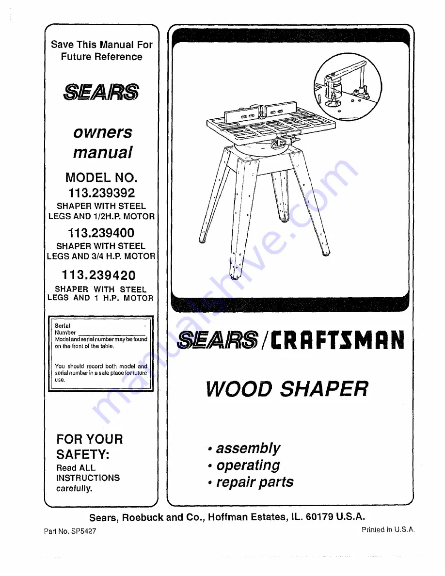
Page 1: ...H P MOTOR 113 239420 SHAPER WITH STEEL LEGS AND 1 H P MOTOR Serial Number Model and serial numbermaybe found on the tront of the table You should record both model and serial numberin a safe place for future use FOR YOUR SAFETY Read ALL INSTRUCTIONS carefully Part No SP5427 I RRFTSMRN WOOD SHA assembly operating repair parts Sears Roebuck and Co Hoffman Estates IL 60179 U S A Printed in U S A ...

Page 2: ... a job it was not designed for 11 WEAR PROPER APPAREL Do not wear loose clothing gJoves neckties or jew elry rings wrist watches to get caught in moving parts NONSLIP footwear is recommended Wear protective hair covering to contain longhair Floil long sleeves above the elbow 12 USE SAFETY GOGGLES HEAD PROTECTION Wear safety goggles must comply with ANSI Z87 1 at all times Everyday eyeglasses are n...

Page 3: ...utter is rotating 14 Rubbish shavings stock or other objects or material should not be allowed on the floor where they may be a tripping hazard 15 Use working forms patterns or ho ders wherever pos sible and keep them maintained Care should be taken that the work is securely fastened in these fix tures Stock is often of such size or shape that it must be clamped in a holder before being shaped The...

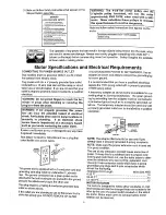
Page 4: ...r cord is worn orcut or damaged in any way have It replaced immediately Yourshaper is wired for 120 volts and has a plug that looks like the one shown below 3J_ONO _ PLUO G_OUNtJ_D OU1 L_t P_OV 3 This power tool is equipped with a 3 conductorcord and grounding type plug listed by Underwriters Labotate ties fine ground conductorhas a green jacket and is attached to the tool housing at one end and t...

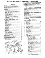
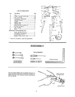
Page 5: ...n and the list of Loose Parts to make certain all items are accounted for before discarding any packing material _f any parts are missing do not attempt to assembte the Shaper plug in the power cord or turn the swilch on untilt_qe missing parts are obtained and are installed correclly Remove the protective oil that is applied to the table lop and edges of the table Use any ordinary household type ...

Page 6: ...ARE FOR MOUNTING TOOL Screw Hex Hd 5116 18 x 3 3 Lockwasher 5 t6 External 3 Nut Hex Jam 5 16_18 3 Washe 11 32 x 11 16 x 1 16 3 These parts contained in Loose Part bag 508411 7 16 _NCH WRSNCH 1 2 INCH WRENCH 9t16 1NCH WRENCH ASSEMBLY t TOOLS NEEDED i Coal the spindte assembly with cup grease being sure to wipe same of the grease intothe elevating slot milled in the spindle assembly Use a generous a...

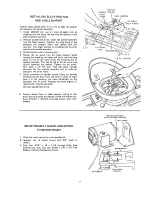
Page 7: ...urn This witl allow enough clearance for the spindle assembly slot to slide on dog point end of set screw 5 Check operation of spindle several times by moving elevating control lever back and forth in order to make sure it is not binding yet slides effectively on the dog point end of screw Readjust set screw slightly if required for smooth operation Reinstall spindle lock knob 6 Position shaper ba...

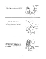
Page 8: ...ley on motor shaft with closed end of pulley facing out Tighten pulley set screw securely 5_21N SETSCREW WRENCH MOTOR PULLEY J FLUSH WITH SHAFT 2 Using table insert as a spacer position motor on motor mount plate to provide a distance of 1 4 inch from mounting edge of motor mount plate as shown Tighten the four motor mount bolts securely and recheck for correct positioning MOTOR MOUNT PLATE MOTOR ...

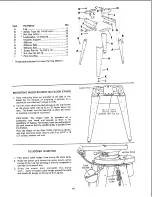
Page 9: ...and lockwashers packed with the switch I ASSEMBLING STEEL LEGS 1 Assemble the two 2 End Stiffeners and the two 2 Side Stiffeners using four 4 1 4 20 Truss head screws The End Stiffeners are placed on top of each Side Stiffener as shown Insert screws through the 9 32 inch diameter holes and finger tighten 1 4 20 nuts 2 Attach the four 4 legs to the side and End Stiffener using 1 4 20 screws lockwas...

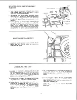
Page 10: ...d to allow the motor to overhang rear edge of toot stand CAUTION The shaper must be mounted on a substantial tool stand and secured so there is no possibility of tipping The Shaper must be positioned on the tool stand so that the spindle pulley is guarded from the bottom Place the Shaper on the Steel LEGS Position as shown and align mounting holes Secure with 3 ea 5 16 x 18 x 3 screws washersand n...

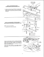
Page 11: ...GULAR SHAPING ONLY NOTE Fence must be removed 1 Assemble Cutter Guard as illustrated I 4 2B LOCKNUT R H SUP_ RT Align the guard support so that it is centered on the shaper spindle It may be necessary to loosen the 5 16 18 screws which secure the support bracket to the channels to perform this adjustment After the alignment is achieved tighten all four screwssecurely Instatl Cutter Guard Assembly ...

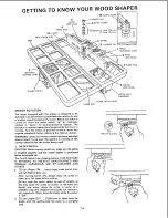
Page 12: ... selected always check to be sure the spindle is rotating in the correct direction for the cutter being used 1 ON OFF SWITCH CAUTION Before turning switch on make sure the cutter is installed properly and the keyed washer is positioned below the spindle nut The On Off SwiIch has a locking feature THIS FEATURE IS INTENDED TO PREVENT UNAUTHORIZED AND POSSIBLE HAZARDOUS USE 8Y CHILDREI_ AND OTHERS a ...

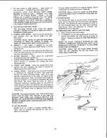
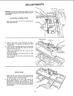
Page 13: ...nism After the desired fence position has been selected it is secured by tightening the fence lock knob The fence faces will close in from a maximum three inch opening down to one inch for small diameter cutters by _oosening the two screws in the front of each face and sliding the face to the desired posiiton The screws must be tightened secureiy after each setting CAUTION The opening between inne...

Page 14: ...rom the miter slot Tighten fence attaching bolts after fence has been correctly positioned Check this adjustment after tightening bolts to make sureit did not change Lock all controls securely after desired settings have been completed STRAIGHT EDGE FENCE FACE FENCE FACES 1 Loosen the four 4 screws as shown and slide each fence face in as close to the cutter as possible but do not permit the cutte...

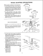
Page 15: ...the spacer is positioned below the cutter how the spacer provides a bearing surface for the uncut edge of the board in addition to its use as a spacer in vertical positioning of the cutter _ SPACER DIRECTION OF ROTATI O N 1 SPACER TABLE INSERT KEYED WASHER TER DIRECTION OF FEED This same cutter can be inverted and mounted to produce a shape with the board fed through in the opposite direction IF D...

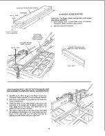
Page 16: ...END SHAPING WITH USE OF MITER GAUGE AND HOLD DOWN CLAMP OPTIONAL ACCESSORIES 1 NEVER use the Miter Gauge on the Shaper without the Hold down Clamp installed and the workpiece clamped 2 Both fence faces MUST be positioned so the workpiece canaot contact them 3 Adjust the head of the miter gauge so the end of the workpiece to be shaped will be exactly parallel to the miter gauge slot in the table Th...

Page 17: ...haping cuts remove power cable from electrical source remove the fence assembly select the shaper collar that will position the cutter to obtain the desired pattern and lock the shaper collar and cutter on the spindle NOTE A shaper collar may be located above or below a cutter or between the two cutters selected DIRECT OF ROTATION SPeNDS AUnT _ DIRECTION KEYED WASHER _OF FEED SPACER SHAPER COLLAR ...

Page 18: ...er until the workpiece contacts the shaper collar WARNING Do not attempt to shape warped lumber Workpiece MUST contact the FRONT of the cutter and collar toward the miter gauge slot 5 In addition 11he following operations are some which can be performed on the shaper shaping with a pattern tongue and groove joints reading and fluting etc Power Tool Know How Handbooks are available See Recom mended...

Page 19: ...supply the bearings with oil Use a good grade of medium weight mineral oil such as automobile engine oi SAE 20 3 If disassembly of the motor is necessary it should be returned to your nearest Sears retail or mail order store in order to prevent voiding the guarantee 4 NOTE The speed of this motor cannot be regulated or changed Every effort should be made to prevent foreign material from entering t...

Page 20: ... 15 accordingly 2 Maintain continuous feed 3 Sharpen or replace cutter 4 Adjust belt for proper tension 5 Replace or resharpen cutter 1 Work piecenot being held firmly against fence and or table 2 Interrupted feed past cutter 3 Dull cutter 4 Belt slipping causing cutter speed to vary 5 Cutter blades not concentric Blade segmentshave uneven lengths 6 Work beingfed too rapidly 7 Quality of wood not ...

Page 21: ...ho d in periods caused by low line voltage etc 2 Shorted capacitor 3 Loose or broken connections ii ii ii 1 Starting switch not operating 2 Voltage too low to permit motor to reach operating speed 3 Fuses or circuit breakers do not have sufficient capacity L _ _ _ 1 Motor overloaded 2 Fuses or circuit breakers do not have sufficient capacity 3 Starting switch not operating motor does not reach spe...

Page 22: ...REPAIR PARTS PARTS LiST FOR CRAFTSMAN WOOD SHAPER MODEL NO 113 239392 113 239400 AND 113 239420 40 41 42 33 35 1 32 6 13 22 ...

Page 23: ...se Spindle Assembly See Figure 5 Plate Guard Belt V 1 2 x 33 Bolt Carriage 5 16 18 x 1 1 4 Washer 21 64 Nut Hex 5 16 18 Mount Motor Screw Mach 5 16 18 x 3 4 Hex Hd w Loekwasher Key Part No No Description 27 72003 28 STD 503102 29 39230 30 STD 551037 31 STD 523710 32 39216 33 72027 34 72024 35 72025 36 STD 551231 37 STD 523112 38 72005 39 60262 40 STD 541525 41 70001 42 56634 43 72026 44 72023 45 6...

Page 24: ...n 1 2 3 4 5 6 7 9 t0 11 t2 72008 STD 511005 38711 38612 18451 38413 38531 38110 38533 STD 512507 STD 551012 38532 Fence Assembly Complete Screw Pan Hd 10 24 x 1 2 Bracket Retaining Knob Adjusting Washer Spring Frame Knob Shoe Assy Fence Plate Work Face Right Screw Pan Hd 1 4 20 x 3 4 Washer Plain t 4 Plate Work Face Left Standard Hardware Item May be Purchased Locally L24 ...

Page 25: ...Hd 1 4 20 x 5 8 t Nut Hex 1 4 20 f Lockwasher 1 4 External Channel Support Stiffener Stiffener Side Stiffener End I Screw Pan Hal Ty A N8 x 1 2 t Nut Hex Hd 3 8 16 t Foot Leveling Bag of Loose Parts Not lllus HARDWARE FOR MOUNTING TOOL STD523130 1 Screw Hex Hd 5116 18 x 3 STD551131 t Lockwasher 5 16 External STD541231 t Nut HexJam 5 16 18 STD551031 Washer 11 32 ID Standard Hardware Item May be pur...

Page 26: ...er Switch Screw Pan Hd No 6 x 3 4 Bracket Switch Mounting Screw Pan Hd Plastite No B x 3 8 _Standard Hardware Item May be Purchased Locally Does Not Include Key No 3 Order Separately If Required FEGURE 5 SPINDLE ASSEMBLY ii Key Part No No Description 39615 2 39711 3 39616 4 39617 5 507727 6 STD 503103 STD 32801ti Spindle Assembly Complete Nut Spindle Washer Keyed Spacer 1 4 Spacer 7 16 Spindle Ass...

Page 27: ...E OUTLET UNTIL ALL ASSEMBLY STEPS ARE COMPLETED 1 Open motor connector box cover located on left end of motor viewed from rear of sawl using a flat blade screwdriver 2 Remove GREEN SCREW and Iockwasher and insert screw through round metal terminal on the end of the GREEN wire of power cord with Iockwasher between terminal and motor frame See illus 3 Reinsert GREEN SCREW in the tll readed hole Tigh...

Page 28: ...vice simply contact any Sears Service Center and most Sears Roebuck and Co stores Be sure to provide all pertinent facts when you call or visit The model number of your wood shaper will be found on a plate attached to your wood shaper on the front of the table WHEN ORDERING REPAIR PARTS ALWAYS GIVE THE FOLLOWING INFORMATION PART NUMBER PART DESCRIPT ON MODEL NUMBER 113 239392 113 239400 113 239420...

Reviews: