background image

Summary of Contents for 351.226712

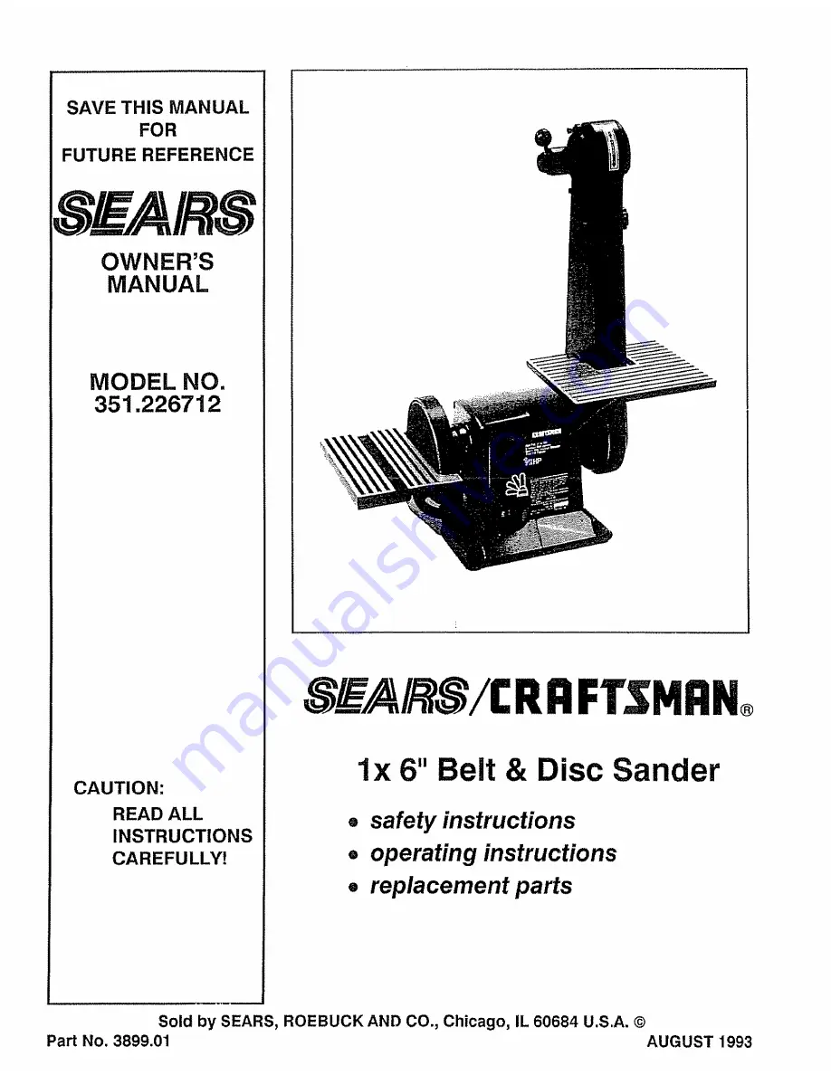
Page 1: ...R S MANUAL MODEL NO 351 226712 CAUTION READ ALL INSTRUCTIONS CAREFULLY RRFrSHRN l x 6 Belt Disc Sander safety instructions operating instructions replacement parts Sold by SEARS ROEBUCK AND CO Chicago IL 60684 U S A Part No 3899 01 AUGUST 1993 ...

Page 2: ... unintentional use of power tools TOOL SHOULD BE MAINTAINED a Always unplug power tool prior to inspection b Consult owner s manual for specific maintainirlg and adjusting pr ocedureso c Use clean belts and keep the tool clean for safest operation d Remove adjusting keys and wrenches Form habit of checking to see that keys and adjusting wrenches are removed before turning tool on e Keep all guards...

Page 3: ...isc sander as described in this manual pages 6 through 8 4 Be sure motor runs clockwise on disc side Abrasive belt must travel down 6_ 8_ 9 Perform disc sanding on down side right side The disc should pull work towards the table Support workpiece Use backstop or work table The backstop for the abrasive belt is the belt platen Key No 25 as described in Operating Instruc tions page 7 Do not force wo...

Page 4: ... equipment grounding conductor If repair or replacement of the electrical cord or plug is necessary make sure the equipment grounding con ductor is not connected to a line terminal WARNING CHECK WITH A QUALIFIED ELECTRI CIAN OR SERVICE PERSONNEL IF THE GROUNDING INSTRUCTIONS ARE NOT UNDERSTOOD OR IF IN DOUBT AS TO WHETHER TOOL IS PROPERLY GROUNDED PROPERLY GROUNDED OUTLET _ PRONG _ This toot is in...

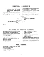
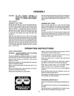
Page 5: ... should be filed with the carrier for fast action Parts listed below are not attached to sander and should be located and accounted for Refer to Figure 4 page 10 Key No 13 6mm loO Hex nut 2 each e Key Noo 54 6mm Flat washer 2 each e Key No 11 6 1o0x 20ram Socket head bolt 2 ea e Key No 5 Disc guard e Key No 8 Dust chute e Key No 12 t0 24 x 1 2 Pan head screw 2 each Key Nos 4 1 ea 6 2 ea 7 2 ea 54 ...

Page 6: ...adjust if necessary_ Always wear eye protection or face shield_ Be sure that the gap between the disc and disc table is 1 16 or less Secure guard and table position by tighten ing the socket head bolts and hex nuts Key Nos 11 13 and 9 ASSEMBLE BELT TABLE Mount the belt table Key No 47 to the belt housing using a socket head bolt lock washer and fiat washer Key Nos 49 50 and 51 Be sure that the gap...

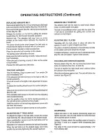
Page 7: ...crew with the 4mm hex wrench Use a 8mm wrench to tighten locknut to lock positton_ ADJUSTING BELT TABLE ANGLE To adjust the angle of the belt table loosen the socket head bolt Key No_49 and adjust to the desired angle Use a combination square to set the belt table at 45 or 90 to the abrasive belt Adjust for 1 6 clearance between the belt and the table_ When the belt table is at the desired angle l...

Page 8: ... disc table loosen the two knobs and adjust to the desired angle When disc table is at desired angle lock it into position by securely tightening the knobs ABRASIVE DISC FINISHING Abrasive disc sanding is well suited for finishing small flat surfaces and convex curved edges Move the workptece across the down side right of the face of the abrasive disc The abrasive disc produces almost no abrasive ...

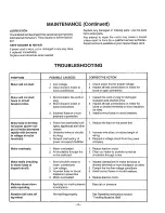
Page 9: ...akers in powerline t Power line overloaded with lights appliances and other motors 2 Undersize wires or circuits too long General overloading of power company s facilities 1_ Motor overloaded 2_ Air circulation through the motor restricted 1 Short circuit in motor or loose connections 2 Low voltage 3 incorrect fuses or circuit breakers in power line 4 Motor overloaded Applying too much pressure to...

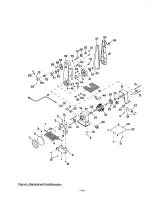
Page 10: ...58 4O 39 9 41 38 29 24 25 27 19 19 Figure 4 Replacement Parts Illustration_ 10 ...

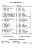
Page 11: ...0 51 STD851010 52J 3319 00 53 3806 00 54 STD851006 Belt table 1 Work stop 1 10 1 50 x 25mm Socket head bolt 1 10mm Lock washer 1 10mm Fiat washer 1 Belt platen 1 6 1 0 x 10ram Socket head bolt 2 6mm Flat washer 6 t0 Serrated washer Switch with key Armature Stator 1 1 1 1 55 8TD582062 56 827800 57 8279B0 58 8280 00 3AMl 15mm Retaining ring Ext 2 Tracking wheel 1 Tracking wheel cam 1 Tracking bracke...

Page 12: ...cts when you call or visit The model number of your Belt Disc Sander will be found on the front of the unit All parts listed may be ordered from any Sears Service Center and most Sears stores If the parts you need are not stocked Iocatly your order Will be electronically transmitted to the Sears Repair Parts Distribution Center for handling Wtlen ordering repair parts always give the following inf...

Reviews: