background image

Summary of Contents for 358.796920

Page 1: ...l Safety Rules Precautions and Operating Instructions Failure to do so can result in serious personal injury 2 _ 6 Eng_n o Assembly o Operation Fu nU_x t 6 1 e Maintenance Repair Parts I Sold by Sears Roebuck and C Cllicago IlL 60684 U S A 66517 3 24085 1 24085 PRINTEO IN U S A ...

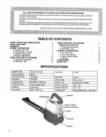
Page 2: ...NERAL MAINTENANCE A Air Filter Care B Fuel Tank Upkeep C Starter Rope Repair D Storage ACCESSORIES PARTS LIST SPECJFI ATJ N ENGINE TYPE DISPLACEMEN31 OPERATING RPM IGNITION CARBURETOR ON OFF SWITCH STARTER FUELTANK 2 Cycle Air Cooled 28 0 cc 75008200 Solid State All Position Diaphragm Positive Toggle Switch Auto Rewind 400cc 13 5 fl oz MUFFLER VELOCITY AIR VOLUME SPARKPLUG SPARKPLUGGAP MODULE AIR ...

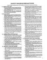
Page 3: ...arbon monoxide 5 Do not wear rubber or any other insulated gloves when using the unit as a vacuum to avoid static electricity shock 6 Donotsettheunitonthegreundtostarttheengine orwhile the engine is running Debris such asgravel sand dust grass etc could be picked up by the air intake and thrown out through the discharge opening damaging the unit property or causing serious personal injury to bysta...

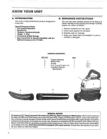
Page 4: ...1 Engine Assembly 1 2 Blower Tube 1 4 3 Nozzle 1 f_l 4 8 oz 2 cycle Engine Oil 1 Operator s Manual 1 Not Shown 3 1 SPECIAL NOTICE For users on U S Forest Land and in the states of California Maine Oregon and Washington All US ForestLand and the statesof CaUfornia PublicResourcesCodes 4442 and 4443 Oregon and Washington require by law that certain inter nalcornbustion enginesoperated onforest brush...

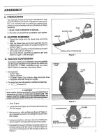
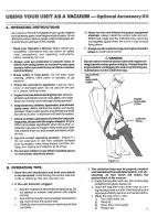
Page 5: ... Store Follow the assembly instructions below o Kit Contents Suction Tube Clamp w Screw 2 Bushel Heavy Duty Collection Bag w Shoulder Strap Adjustable Shoulder Strap for engine o The only tool you will need is a slotted screwdriver _WARNING Stop engine before opening the vacuum inlet door or attempting to insert or remove the suction tube The engine must be stopped and the impeller blades no longe...

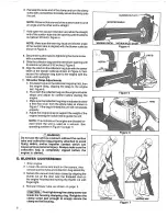
Page 6: ...e starting the engine c Make sure the collection bag strap is adjusted to allow a free flow of air from the elbow tube as shown in Figure 7 Ifthe bag is kinked the unit will not operate properly d Adjust the engine strap to support the weight of the engine leaving the hands free to guide the unit NOTE The controls on the engine are directed for ward when the unit is used as a vacuum See operating ...

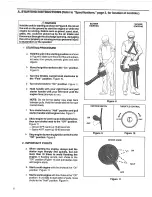
Page 7: ...r lock causes hard starting Attracts water causing corrosion damage 2_ 1 GALLON REGULAR UNLF_DED _ USE THE FOLLOWING OR _ 3 HOW TO MIX FUEL a Pour one half of the gasoline into an approved marked container Do not try to mix fuel directly in the h_el tank b Add entire measure of 2 cycle Engine OiL c Mix d Add remainder of gasoline e Mix thoroughly for one mim te 5 IMPORTANT POINTS TO REMEMBER a Use...

Page 8: ...your left hand until the engine fires attempts to run NOTE Do not let the starter rope snap back between pulls_Hold the handle and let the rope rewind slowly f Turn choke knob to Half position and pull starter handle until engine runs Figure 11 h Allow engine to warm up as indicated below then turn choke knob to the Off position Figure 11 Above 40 1 warm up 10o20seconds Below 40 F warm up 45 60 se...

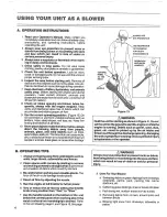
Page 9: ...if the engine stalls Counterclockwise _ to slow engine down 5 Adjust the Idle Speed Screw until the engine idles as slow as possible without the engine stalling t CAUTION The mixture setting is a highly critical adjustment If set incorrectly permanent damage will occur to the engine Do not operate engine at fast throttle fdr prolonged periods while making the mixture adjustment c MIXTURE ADJUSTMEN...

Page 10: ...ch may hurt people or anirnals break glass orcause other damage 1Q ALWAYS USE _EYE PROTECTION USE RESPIRATOR OR FACEMASK FOR DUSTY ENVIRONMENTS HANDLE CONTROL PANEL TO THE _ _ REAR HANDLE OPERATION WITHBOTH HANDLES Figure 13 z_WARNING Hold the unit for starting as shown in Figure 8 Do not set the unit ontheground tostart theengineorwhilethe engine is running Debris such as gravel sand dust grass e...

Page 11: ...n the suction or collection bag tube is clogged Keep vents and tubes free of debris which can accumulate and restrict proper air flow 8 Use the correct operating position Figure 14 Do not overreach or use from unstable surfaces such as ladders trees steep slopes roof tops etc Keep firm footing and balance at all times 9 Do not wear rubber or any other insulated gloves to avoid static electricity s...

Page 12: ...eak down after a short period of time and will form compounds that cause hard starting and damage in 2 cycle engines 1 Inspect the unit for fuel leaks each time it is used Repair or replace parts as necessary 2 Always begin operation with a clean fresh mixture of fuel 3 Drain all fuel from the unit or allow unit to run out of fuel before storing for 30 or more days C STARTER ROPE REPAIIR Repair th...

Page 13: ...het and tuck loose end back under rope leaving a 3 8 to 1 4 inch tail Figure 18 Pull tightly l Wind all but about 10 inches of the rope counter clockwise _ around pulley 11_ Replace pulley inthe housing Be sure the pulley is all the way down and the spring is secured 12 Replace and tighten pulley screw Figure 17 13 Hold the 10 inch slack in the rope and catch rope in pulley notch Figure 19 14 Hold...

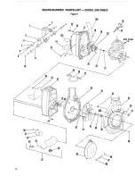
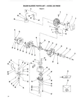
Page 14: ...10 11 SEARS BLOWER PARTS UST _ MODEL 358 796920 Figure 1 2 j 15 16 101 14 13 31 102 25 19 2O 32 o 33 34 43 41 40 42 35 33 38 38 14 ...

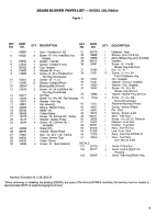
Page 15: ... Housing 44 15168 4 Screw 10 24 x 5 8 16 15677 4 Washer Fan Hsg Shroud Crankcase 17 10821 1 Fan Housing 45 1516 1 Retainer Bearing Shroud 18 42023 1 Spring Starter Pulley 46 15667 1 Spring Tension Right 19 26780 1 Baffle Air 47 15647 Pin Pivot 20 28626 1 Pulley Starter 48 15672 1 Spring Tension Left 21 15479 1 Screw 10 3 4 Hex Hd Pulley 49 94241 1 Ass y Inlet Door 22 15123 1 Washer Starter Pulley ...

Page 16: ...16 SEARS BLOWER PA_ L_S_ MODEL 358 796920 Figure 2 5 14 15 o 18 19 29 21 22 13 28 22 21 12 56 55 52 53 26 12 72 3 SPARK ARRESTOR KIT 7 8 11 ...

Page 17: ...rb_Case 2 Spring Starter Dog 53 23807 1 Knob Choke 1 Ass y Crankshaft Rod 54 15675 4 Screw 8 18x 5 8 Phil 1 Bearing Wrist Pin 55 15660 1 Screw 10 14x 3 8 Throttle 2 Washer Thrust Crankcase 56 15658 1 Washer Flat Throttle 2 Bearing Crankshaft 57 15614 1 Knob Throttle 1 Crankcase Ass y 58 23575 1 Nut Grounding Switch Incl 21 23 59 24569 1 Washer Ground 2 Seal Crankcase 60 26766 1 Switch Toggle 1 Was...

Page 18: ...rottle Valve Shaft Assembly Throttle Idle Speed Screw Spring Throttle Return Spring High Speed Mixture Needle Needle High Speed Mixture Plug 5 16 Dia Welch Screw Pump Cover Cover Fuel Pump Gasket Fuel Pump Diaphragm Fuel Pump Screen Fuel inlet Ring Throttle Retainer Valve inlet Needle Spring Metering Lever Lever Metering Pin Metering Lever Screw Metering Lever Pin Gasket Metering Diaphragm Diaphra...

Page 19: ...Blower Upper 1 66517 Operator s Manual VACUUM KIT 71 79991 Optional Accessory Kit 3 Ol 4 KEY NO 1 2 3 4 5 6 101 PART QTY NO 1 94394 1 94231 1 94227 1 15671 1 94230 1 94232 Decal 1 26937 DESCRIPTION Strap Shoulder Engine Tube Collection Bag Bag Collection w Strap Strap Tie Clamp Suction Tube Tube Suction Decal SuctionTube 19 ...

Page 20: ... ITEM GAS POWER BLOWER If the parts you need are not stocked locally your order will be elec tronically transmitted to a Sears Repair Parts Distribution Center for expedited handling When you buy merchandise from Sears you get an extra something that nobody else can 0ffe Sears Service Across town or across the country Sears Service follows you pro viding trustworthy competent ser vice technicians ...

Reviews: