background image

Summary of Contents for 536.885201

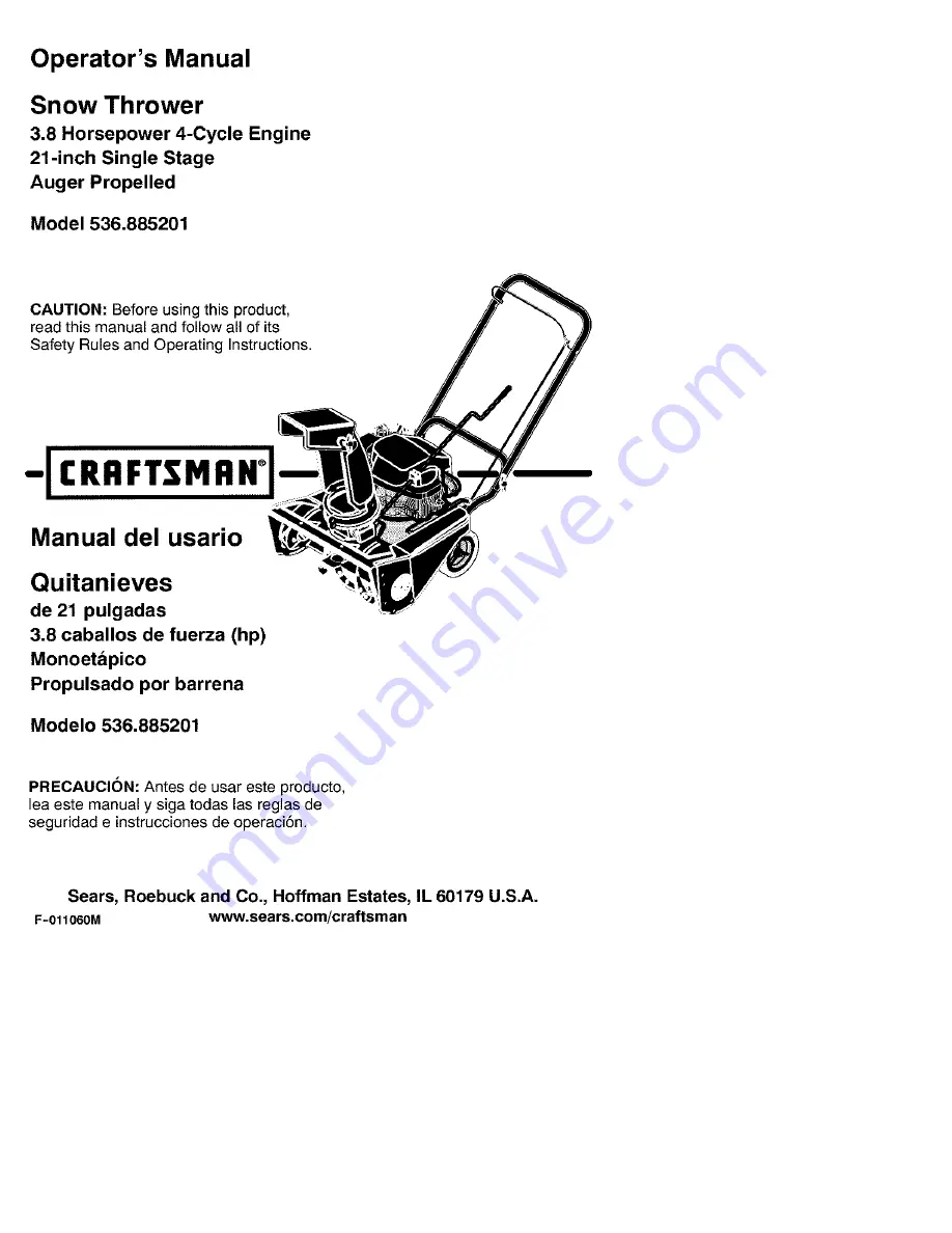
Page 1: ...its Safety Rules and Operating Instructions CRRFTSMRN Manual del usario Quitanieves de 21 pulgadas 3 8 caballos de fuerza hp Monoetapico Propulsado por barrena Modelo 536 885201 PRECAUCION Antes de usar este producto lea este manual y siga todas las reglas de seguridad e instrucciones de operaci6n Sears Roebuck and Co Hoffman Estates IL 60179 U S A F 011060M www sears com craftsman ...

Page 2: ...n the equipment according to the instructions contained in the owner s manual WARRANTY SERVICE IS AVAILABLE BY RETURNING THE CRAFTSMAN SNOW THROWER TO THE NEAREST SEARS SERVICE CENTER DEPARTMENT IN THE UNITED STATES THIS WARRANTY APPLIES ONLY WHILE THIS PRODUCT IS IN USE IN THE UNITED STATES This warranty gives you specific legal rights and you may also have other rights which may vary from state ...

Page 3: ... the equipment is to be used and remove all doormats sleds boards wires and other foreign objects F 011060M 2 Disengage all cIu ches before starting the engine motor 3 Do not operate the equipment without wearing adequate winter outer garments Wear footwear that will improve footing on slippery surfaces 4 Handle fuel with care it is highly flam mable a Use an approved fuel container b Never remove...

Page 4: ... snow thrower near en closures automobiles window wells drop offs and the like without proper ad justment of thesnow discharge angle Keep children and pets away 14 Donot overload the machine capacity by attempting toclear snow attoo fast arate 15 Never operate the machine athigh trans port speeds onslippery surfaces Look be hind and use care when backing up 16 Never direct discharge atbystanders o...

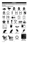
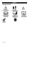
Page 5: ...e Run H N Engine Off Engine Stop On Choke Off Choke On Neutral Throttle Primer Button Ignition Key Q Ignition Off Ignition On Drive Clutch Forward Reverse Auger Clutch Auger Collector Engage Push To Engage Electric Starter Fuel Oil Fuel Oil Mixture f d Discharge DOWN Discharge UP Discharge LEFT Discharge RIGHT Weight Transfer Weight Transfer Transmission Ignition Key Lift Handle To Depress Pedal I...

Page 6: ...TANT Read Owner s Manual Before Operating This Machine DANGER Thrown Objects Keep Bystanders Away DANGER Avoid Injury From Rotating Auger Keep Hands Feet And Clothing Away WARNING DANGER Stop The Engine Before Unclogging Discharge Chute WARNING Hot Surface STOP F O11060M 6 ...

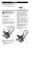
Page 7: ...ctor Figure 1 HOW TO REMOVE FROM THE CARTON 1 Locate and remove container of Craftsman 5W30 oil F 011060M 2 3 4 5 6 7 Locate all parts packed separately and remove from the carton NOTE Place fuel stabilizer in a safe place until needed for storage Remove and discard the packing material from around the snow thrower Cut down all four corners of the car ton and lay the panels flat Loosen the knobs h...

Page 8: ...ave been completed _ The discharge chute rotates freely _ No remaining loose parts in carton While learning how to use your snow thrower pay extra attention to the fol lowing important items _ Engine oil is at proper level _ Make sure gas tank is filled properly with clean fresh unleaded gasoline _ Become familiar with all controls their location and function Operate controls before starting engin...

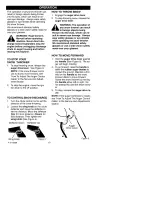
Page 9: ...ever Choke Cont_I Primer Bu_on Figure 3 Auger Drive Lever Starts and stops the auger Crank Assembly Changesthe direction of snow throwingthroughthe discharge chLOe Chute Deflector Changes the distance the snow is thrown Discharge Chute Changesthe direction the snow is thrown Ignition Lever Must be moved to the on position to start the engine RecoilStarter Handle Startsthe en gine manually Choke Co...

Page 10: ...lector to set the distance Move the deflector Up for more distance Down for less distance Then tighten the wing knob See Figure 4 Deflector Down Deflector Up HOW TO THROW SNOW 1 Engage the auger drive lever 2 To stop throwing snow release the auger drive lever _ WARNING The operation of any snow thrower can result in foreign objects being thrown into the eyes which can re sult in severe eye damage...

Page 11: ... EM TWC if so equipped Include any user ad justable features therefore no other ad justments are needed _lb WARNING Experiences in dicates that alcohol blended fuels called gasohol or those using ethanol or methanol can attract moisture which leads to separation and formation of acids during storage Acidic gas can dam age the fuel system of an engine while in storage NOTE To avoid engine problems ...

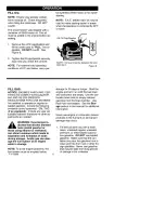
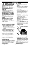
Page 12: ...n 2 Make sure the auger drive lever is in the disengaged RELEASED position 3 Move the choke control to the full choke position 4 Push the primer button while cov ering the vent hole as follows Re move finger from primer button between primes Do not prime if temperature above 50 F 10 C Push two time if temperature is 50 F 10 C to 15 F 10 C Push four times if temperature is below 15 F 10 C Push five...

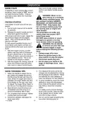
Page 13: ...rby areas may exceed 150 1 Avoid these areas DO NOT allow children or young teenagers to operate or be near snow thrower while it is operating _lb ARNING Do not attempt to remove any item that may become lodged in auger without taking the following precau tions Release auger drive lever Move the ignition lever to the stop position to stop the engine Disconnect spark plug wire Do not place your han...

Page 14: ...d rapidly and easily by walking at a moderate rate For snow or drifts of a greater depth slow your pace to allow the discharge chute to dispose of the snow as rapidly as the auger re ceives the snow 2 Plan to have the snow discharged in the direction the wind is blowing WET PACKED SNOW Move slowly into wet packed snow If the wet packed snow causes the auger to slow down or the discharge chute be g...

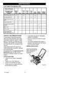
Page 15: ... from the warranty the operator must maintain the snow thrower as instructed in this manual Some adjustments will need to be made periodically to properly maintain your snow thrower All adjustments in the Service and Ad justments section of this manual should be checked at least once each season AFTER EACH USE Check for any loose or damaged parts Tighten any loose fasteners Check and maintain the ...

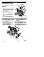
Page 16: ...r reverse the above steps Top Cover A B C C Crank ssembly Rod Figure 9 HOW TO REMOVE THE BELT COVER 1 Remove the screws A and nuts B from the belt cover 2 Remove attachment screw C from the rear of the belt cover 3 Remove the belt cover from the unit 4 To install the belt cover reverse the above steps NOTE The belt cover has belt guides moulded onto the inside of the cover When you install the bel...

Page 17: ...ly remove the oil fill cap dip stick Oil will begin to flow into the oil drain pan After all the oil has drained from the engine set the snowthrower in the operating position Fill the engine with S A E 5W30 oil Make sure the oil reaches the FULL mark on the oil fill cap dipstick DO NOT OVERFILL NOTE For extreme cold operating conditions of 0 F and below use a par tial synthetic 0W30 motor oil for ...

Page 18: ...o tension on the idler arm 3 Tighten the nut that holds the cable tension spring If belt stretch has occured move the end the auger drive cable to the out side hole as follows 1 Loosen the nut that holds the cable tension spring See Figure 14 2 Move the cable tension spring to ward the front of the unit to achieve maximum cable slack 3 Remove the upper end of the auger drive cable from the auger d...

Page 19: ...ver Brake Arm Adjuster Nut 3 Make sure the auger drive lever is in the disengaged released posi tion Figure 16 4 Turn the adjuster nut See Figure 16 in or out until the brake arm is in contact with the auger drive belt See Figure 17 5 Hold the auger drive lever in the en gaged position and push the brake arm down to remove all slack Auger Drive Belt 6 In correct adjustment there will be 1 4 inch c...

Page 20: ...remove the belt guide rotate the belt guide down 5 Remove the idler screw and idler pulley from the idler arm See Figure 19 6 Remove the auger drive belt from the engine pulley and pull through side of motor box See Figure 20 7 To remove the auger drive belt from the impeller pulley move the idler arm to the engaged position This will provide clearance between the impeller pulley and the brake arm...

Page 21: ...er shaft threads are left hand turn clockwise to remove 4 To keep the auger from rotating set a 2 x4 piece of wood on the cen ter paddle to secure auger 5 Remove bolts A washer F and nuts B from front of right cover See Figure 23 6 Remove screw C from back of right cover 7 Remove bolts D and nuts E AF Right Cover C 9 Slide the auger out of the bearing on the left side of the auger hous ing 10 To i...

Page 22: ...rent Australian and New Zealand limitations regarding electromagnetic interference If you have difficulty starting the snow thrower adjust or replace the spark plug Replace the spark plug if the elec trodes are pitted or burned or if the por celain is cracked Follow the instructions below TO adjust 1 Clean spark plug by carefully scraping the electrodes Do not sand blast or use a wire brush 2 Be s...

Page 23: ...tracts water It acts on the gasoline to form acids which damage the engine F 011060M 1 2 3 4 5 TO remove gasoline run the engine until the fuel tank is empty and the engine stops If you do not remove the gasoline use fuel stabilizer supplied with unit or purchase Craftsman Fuel Stabi lizer No 3550 Add fuel stabilizer to any gasoline left in the tank to mini mize gum deposits and acids If the fuel ...

Page 24: ...d refill with fresh fuel Excessive vibration Damaged auger assembly Repair or replace the auger assembly Unit fails to propel itself Replace drive beit Drive belt ioose or damaged Incorrect adjustment of auger drive cable Auger drive belt loose or damaged Auger control cable not adjusted correctly Discharge chute clogged Adjust auger drive cable Unit fails to discharge snow Adjust auger drive belt...

Page 25: ...ou are responsible for the performance of the re F 011060M quired maintenance listed in your Owner s Manual but Sears Roebuck and Co will not deny warranty solely due to the lack of receipts or for your failure to provide written evidence of the performance of all scheduled mainte nance As the small oft road engine owner you should however be aware that Sears Roe buck and Co may deny you warranty ...

Page 26: ... 011060M 26 Sears Roebuck and Co according to Subsec tion 4 below Any such part repaired or re placed under the ECS Warranty shall be warranted for any remainder of the ECS War ranty Period 2 Any warranted emissions related part which is scheduled only for regular inspection as specified in the Owner s Manual shall be warranted for the ECS Warranty Period A statement in such written instructions t...

Page 27: ...used by the use of such anunapproved add on ormodified part EMISSION RELATED PARTS INCLUDE THE FOLLOWING 1 Carburetor Assembly and its Internal Com ponents a Fuel filter b Carburetor gaskets c Intake pipe 2 Air Cleaner Assembly a Air filter element 3 Ignition System including a Spark plug b Ignition module c Flywheel assembly 4 Catalytic Muffler if so equipped a Muffler gasket if so equipped b Exh...

Page 28: ...trucciones contenidas en el manual det propietario EL SERVlCIO DE GARANTiA SE PUEDE OBTENER LLEVANDO EL QUITANIEVES DE CRAFTSMAN AL CENTRO DEPARTAMENTO DE SERVICIO SEARS MAS CERCANO EN LOS ESTADOS UNIDOS ESTA GARANTiA ES VP LIDA SOLO CUANDO ESTE PRODUCTO ES USADO EN LOS ESTADOS UNIDOS Esta garantia le otorga derechos lega es especificos yes posibie que tenga otros derechos los cuales varian de est...

Page 29: ...instrucciSn apropiada 3 Mantenga el area de operaci6n del quita nieves libre de personas especialmente nifios pequefios y mascotas F 011060M 4 Tenga mucho cuidado para evitar resba Iones o cafdas especialmente cuando es te retrocediendo PREPARACK N 1 2 3 4 Inspeccione completamente el Area don de se usara el quitanieves y retire todas Ins esteras trineos tableros cables y otros objetos extrafios D...

Page 30: ...ier re paraci6n ajuste o inspecci6n a Ia unidad F 011060M 11 12 13 14 15 16 17 18 19 3O Cuando limpie repare o inspeccione la unidad asegSrese de que la barrena im pulsor y todas las partes m6viles se en cuentren detenidas y que todos los controles esten desenganchados Desco necte el cable de de la bujJa y mant6ngalo alejado de Ia bujia para evitar un arranque accidental Tome todas las precaucione...

Page 31: ... el motor se enfrie antes de almacenarlo en cualquier recinto 3 4 Siva a almacenar el quitanieves por un periodo prolongado siempre consulte las instrucciones del manual del operador donde encontrara detalles importantes Mantenga o reemplace las etiquetas de seguridad e instrucciones segt_n sea ne cesario 5 Mantenga el quitanieves en marcha unos cuantos minutos despues de despejar la nieve para ev...

Page 32: ...imbolos de control y operacion Despacio R_pido Arranque electrico Arranque de motor o I Motor en maroha Motor parado Apagado Encendido H N Ahogador Ahogador desactivado activado Neutro Acelerador Boton cebador Llave de encendido Ignicion Ignicion desactivada activada Embrague de propulsion Colector de barrena F 011060M Avance Marcha atras de barrena O_onar 0 Enganchar el arranque electrico Transmi...

Page 33: ...r para desenganchar Retirar para parar Simbolos de advertencia de seguridad N PELIGRO PELIGRO Objetos lanzados Mantenga alejados a los transeuntes Objetos lanzados Mantenga alejados a los transet_ntes ADVERTENCIA IMPORTANTE Lea el manual del propietario antes de operar esta maquina PEUGRO Evite las lesiones que pueds causar la barrena rotatoria Mantenga las manos los pies y la ropa fuera de su al ...

Page 34: ... Figura 1 C6MO SACAR EL QUlTANIEVES DE LA CAJA 1 Localice y retire la botella de aceite de motor Craftsman 5W30 2 Localice todas las piezas empacadas por separado y saquelas de la caja NOTA Coloque el estabilizador de com bustible en un lugar seguro hasta que se necesite para almacenar Ia unidad 3 Retire y descarte todo el material de em paque alrededor de la unidad 4 Corte cada una de las cuatro ...

Page 35: ...as instruccio nes de ensamblado _ El tubo de descarga gira libremente _ No quedan piezas sueltas en la caja de cart6n AI mismo tiempo que aprende a usar su qui tanieves preste mucha atenci6n a ios deta lies siguientes El aceite del motor est_ al nivel adecuado AsegSrese que el tanque de gasolina este Ileno con gasolina limpia fresca y sin plo mo Familiaricese con todos los controles su ubicaci6n y...

Page 36: ...eI ahogador Figura 3 Palanca de propulsion de la barrrena Ac cion8 y detiene la barren8 Manivela de ajuste Cambia la direcci6n de Ia descarga de nieve Deflector del tubo de descarga Cambia la distsncia del Ianzamiento de 18nieve Tubo de descarga Cambi8 18direcci6n en que se lanza la nieve F 011060M 36 Palanca de ignicion Debe moverse a la posici6n de encendido para 8rrancar el motor Manija de arra...

Page 37: ...a el deflector hacia ARRIBA para mayor distancia hacia ABAJO para una distancia menor Luego apriete la pe rilla de mariposa yea la Figura 4 Deflector Deflector arriba abajo Perilla de mariposa Figura 4 COMO LANZAR LA NIEVE 1 Enganohe la palanca de propulsion de la barrena F O11060M 2 Para detener la descarga de nieve suet te la palanca de propulsion de la ba rrena _1 ADVERTENCIA La operaoibn de ou...

Page 38: ...0 F o menos Tapa varilla de nivet NOTA El nivel del aceite deberA estar en tre la marca Ileno y la marca agregar Figura 6 TIPO DE COMBUSTIBLE AVISO LOS MOTORES QUE EST_ N CER TIFiCADOS PARA CUMPLiR CON LAS ES TIPULAClONES DE LAS NORMAS DE EMiSiON EN EL ESTADO DE CALIFORNIA Y DE LAS NORMAS FEDERALES DE EPA DE EUA PARA MOTORES ULGE Est_n certiflcados para funcionar con gasolina re gular sin plomo Es...

Page 39: ...el derrame Asegt_rese de limpiar cualquier combus tible derramado antes de arrancar el motor Almacene la gasolina en un contendor limpio y aprobado y mantenga la tapa puesta y segura en el contenedor F 011060M 39 ANTES DEARRANCAREL MOTOR 1 Antes de darle servicio a la unidad o de hacer arrancar el motor familiaricese con el quitanieves Aseg5rese de enten der la funci6n y la ubicaci6n de todos los ...

Page 40: ...eo fuerte Esto no causa daflo ni 81 motor ni al 8rrsnoador Con el motor parado limpie tod8 la nieve y humedad de 18cubiert8 det carburador en el area de las palancas de control Asimismo muev8 el control de 8celera ci6n control del 8hogador y manija del arrancador varias veoes _1 DVERTENCIA Nunca arran que el motor dentro de un re cinto cerrado o en areas con poca ventilacibn Los gases de escape de...

Page 41: ...or unos minutos As se derretira lanieve yeihielo acumula dos enetmotor 11 Limpie el quitanieves despu6s de cada USO 12 Quite el hielo la nieve y los residuos de todo el quitanieves EnjuAguelo con agua para quitarle toda la sal y otros productos quimicos Seque el quitanie yes NIEVE SECA Y DE POCA PROFUNDIDAD 1 La nieve que se acumule hasta profundi dades de ocho puIgadas puede quitarse rapida y fac...

Page 42: ...ligencia pot parte del operador Pare re cibir el valor completo de la garantia el ope rador debe mantener el quitanieves de acuerdo a las instruooiones contenidas en este manual Se deben hacer algunos ajustes peri6dica mente para msntener adecuadamente su quitanieves DESPUES DE CADA USO Yea si hay piezas sueltas o da_adas Apriete los sujetadores que esten sueltos Revise y dele mantenimiento ala ba...

Page 43: ...ga los pasos anteriores en orden inverse Cubierta superior A B C C Varade la manivela de ajuste Figura 9 C6MO QUITARLA CUBIERTADECORREA 1 Quite los tornillos A y las tuercas B de la eubierta de eorrea 2 Retire el tornillo de sujeci6n C de la parte trasera de la cubierta de co rrea 3 Retire la cubierta de correa de la unidad 4 Para instalar la cubierta de correa siga los pasos anteriores en orden i...

Page 44: ...3 Saque con cuidado la tapa varilla de ni vel de aceite El aceite empezarA a caer en el reeipiente pare el aceite 4 Despu6s que todo el aceite del motor haya salido coloque el quitanieves en la posici6n de operaci6n 5 Uene el motor con aceite S A E 5W30 AsegSrese de que el aceite alcanza la marca FULL leno en la tapa varilla de nivel de aceite NO SOBREPASE LA MEDIDA NOTA Cuando opere el quitanieve...

Page 45: ...ujeta el reaorte de tension del cable Si se estira la correa coloque el cable de propulsion de la barrena en el otro agujero de Ia manera siguiente 1 Afloje la tuerca que sujeta el resorte de tension del cable Vea la Figura 14 2 Mueva el resorte de tensibn del cable hacia la parte detantera de la unidad pa ra Iograr un maximo de holgura det ca ble 3 Saque el extremo superior del cable de propulsib...

Page 46: ...a suetta o released 4 Haga girar la tuerca de ajuste Vea la Figura 16 hacia adentro o hacia afuera hasta que el brazo del freno quede en contacto con la correa de propulsion de la barrena Vea Ia Figura 17 Palanca de propul si6n de la barrena Brazo del freno 5 Sujete la palanca de propulsi6n de la ba Correa de propulsi6n rrena en la posici6n enganchada y em de Ia barrena puje el brazo del freno hac...

Page 47: ...ena Figura 18 2 Retire la cubierta de la correa Consulte Ia secci6n C6mo sacar la cubierta de la correa 3 Fijese en el trayecto de la correa de propulsibn de la barrena Si necesita ayuda encontrar_ Ia calcomania con el diagrama Brazo guia 4 Retire el tornillo de la guia de la co rrea y la guia de la correa Vea Ia Figura 18 Para quitar la guia de la co rrea gire la guia de correa hacia aba jo 5 Ret...

Page 48: ... sacar la correa de pro pulsion de la barrena vea la Figura 21 8 Para instalar una nueva correa de pro pulsi6n para la barrena siga los pasos anteriores en orden inverso 9 Revise los ajustes del cable de propul si6n de la barrena Consulte la secci6n C6mo ajustar el cable de propulsi6n de Ia bar rena Polea del propulsor Espacio Iibre Correa de pro pulsi6n de la barrena Brazo de freno Figura 21 F O1...

Page 49: ... Ia derecha para sa car 4 Para mantener la barrena sin girar colo que un pedazo de madera de 2 x4 en Ia paleta del centro para inmovilizar Ia barrena 5 Quite los pernos A Iavador F y las tuer cas B de la parte del frente de la cubier ta derecha vea la Figura 23 6 Quite el tornillo C de la parte trasera de Ia cubierta derecha 7 Quite Ios pernos D y las tuercas E 9 Deslice la barrena fuera del sopor...

Page 50: ...or cumple con todas las res tricciones actuales referentes a la interferen oia electromagnetica de Australia y Nueva Zelandia Si tiene dificultades al arrancar su quitanie yes ajuste o reemplace la bujia Reemplace Ia bujia si los electrodos estan picados o quemados o si Ia porcelana est_ partida Siga las instrucciones a continuaci6n Para hater el ajuste 1 Limpie la bujia raspando con cuidado los e...

Page 51: ...etanol a veces Ilamada gasohol atrae agua Esta agua act_a sobre la gasoli na para formar Acidos que daSan el motor t 2 Para remover la gasolina mantenga el motor en marcha hasta que el tanque quede vacio y el motor se pare Si no desea sacar gasolina use el esta bilizador de combustible provisto con la unidad o compre estabilizador de com bustible Craftsman No 3550 ASada es tabilizador de combustib...

Page 52: ...or de la taza del erraticamente de combustible carburador para enjuagar vuelva Perdida de a Ilenar el tanque con otencia combustible fresco Vibracion excesiva Conjunto de Ia barrena dar_ado Repare o reemplace el conjunto de la barren La unidad no La correa de propulsi6n de la Reemplace la correa de avanza por barrena est_ suelta o daflada propulsi6n autopropulsion Ajuste incorrecto del cable de Aj...

Page 53: ...condici6n protegida per la garantia Sears Roebuck and Co reparara su motor pequeSo para vehiculos off road sin costo alguno para usted pot concepto de diag n6stico partes y mano de obra SISTEMA PARA EL CONTROL DE EMISIONES DEL FABRICANTE COBERTURA DE LA GARANTIA Los sistemas para el control de emisiones mo delo 1995 y modelos de aflos posteriores de motores pequeflos paravehfculos off road en Cali...

Page 54: ... motores modelo 1997 y aflos posteriores F 011060M 54 A CAMPO DE APLICAOION Esta garantia de berA aplicarse a los motores peq ue5os para vehiculos off road modelo 1995 y modelos de aSos posteriores en California para otros es tados motores modelo 1997 y modelos de aSos posteriores El Periodo de la Garantia SCE iniciarA en la fecha de entrega del nuevo motor o equipo al comprador original y conti n...

Page 55: ...a SCE Sears Roebuck and Co deberA conservar un suministro de partes garantizadas yrelaciona das conemisiones que sea suficiente para cumplir lademanda esperada deesas partes relaoionadas con emisiones 8 Se puede utilizar cualquier parte de repues torelacionada conemisiones autorizada y aprobada per Sears Roebuck and Co para utilizarse eneldesempeflo decualquier man tenimiento ocambio delaGarantia ...

Page 56: ...r Center 1 800 488 1222 Anytime day or night www sears com For the rep acement pa_s accessories and owner smanuals that you need to do it yourself call Sears PartsDirectSM iiiiiiiiiii 1 800 366 PART 6a m 11 p m CST soo 306 72 s 7d ysaweek iiiiiiiiiii www sears com partsdirect TO purchase or inquire about a Sears Service Agreement iiiiiiiiiii 1 800 827 6655 iiiiiiiiiii 7 a m 5 p m OST_ MOFL Sa Regi...

Page 57: ...CRAFTSMAN 21 3 8HP SNOW THROWER 536 885201 DRIVE COMPONENTS 1 2 _t 45 4 6 5 15 17 21 19 2O 13 17 4O 39 41 38 42 31 29 30 27 28 15 F O11060M 57 ...

Page 58: ...Nut Push Cap 17 760713 Wheel Tire 18 71072 Washer 19 762280 Axle 20 71111 Nut 21 762245 848 Frame Motor Box 22 47792 Bolt 23 71007 Bolt 24 712233 Bolt ShouIder 25 762254YZ Bracket Idler Arm 26 71044 Nut 27 762257 Pulley V Belt 28 762258 Bolt Shoulder 29 762256 Pulley Flat Idler 30 37xl 07 Belt 31 315312 Screw 32 762267 Guide Belt 33 71015 Screw 34 71063 Washer 35 762255 Pulley 36 165x143 Spring 37...

Page 59: ...CRAFTSMAN 21 3 8HP SNOW THROWER 536 885201 AUGER COMPONENTS 6 12 18 17 1 2 3 8 16 14 10 9 18 F O11060M 59 ...

Page 60: ...3 710079 Bolt 4 580251 Retainer Bearing 5 43846 Bearing 6 302628 Bolt 7 338965 Pulley Auger 8 710274 Screw 9 762277 Cover Left Belt 10 762266 Housing Auger 11 312300 Nut 12 71067 Washer 13 579052 Bolt 14 55323 Blade Scraper 15 327072 Auger Assembly 16 580969 Washer 17 762276 Cover Right 18 12342 Screw 19 302626 Screw F O11060M 60 ...

Page 61: ...CRAFTSMAN 21 3 8HP SNOW THROWER 536 885201 HANDLE DISCHARGE COMPONENTS 22 28 23 29 27 31 4 6 5 7 9 10 F O11060M 61 ...

Page 62: ...Bolt 11 712123 Washer 12 780029 Nut 13 762281 Bushing Tensioner 14 762282 Bracket Cable Tensioner 15 762362YZ Rod Crank 16 762289 Grip Crank Rod 17 578309 Pin Clevis 18 579493 Pin Cotter 19 578063 Block Universal Pivot 20 578060 Pin 21 585196 Gear Worm 22 325847 Deflector 23 308931 Pin Pivot 24 71071 Washer 25 334234 Chute Discharge 27 302635 Nut 28 302843 Bolt 29 313686 Bolt 30 762286 Ring Chute ...

Page 63: ... 536 885201 NOTILLUSTRATED DECALS Part No 761150 70141 48x304 48x301 48x302 70142 Description DECAL AUGER CONTROL DECAL DANGER AUGER FOOT DECAL BELT INSTR MINI DECAL 3 8HP 21 DECAL CONTROL PANEL DECAL DANGER CHUTE HANDER F O11060M 63 ...

Page 64: ...CRAFTSMAN 143 023800 REPAIR PARTS 900 178 182 185 93 285 _172 2O7 F O11060M 64 ...

Page 65: ...777 Connecting Rod Ass y Incl 46 46 326t0A Connecting Rod Boit 48 27241 Valve Lifter REPAIR PARTS KEY PART NO NO DESCRIPTION 50 37032 Camshaft NCR 52 29914 Oil Pump Ass y 69 35261 Mounting Flange Gasket 70 34311E Mounting Flange Incl 72 thru 83 306 72 30572 Oil Drain Plug 73 28833 Drain Plug Gasket 75 27897 Oil Seal 80 30574A Governor Shaft 81 30590A Washer 82 30591 Governor Gear Ass y Incl 81 83 ...

Page 66: ...9 30200 Screw 10 24 x 9 16 370A 36261 Lubrication Decal 215 35511 Control Knob 380 640228 Carburetor Incl 184 216 33086 R P M Adjusting Lever 390 590743 Rewind Starter 223 650451 Screw 1 4 20 x 1 400 37029A Gasket Set Incl Items 224 36786 Intake Pipe Gasket Marked PK in Notes Incl Part s 26756 1 260 37213 Blower Housing 28833 1 34338 1 261 30200 Screw 10 24 x 9 16 36783 1 36786 1 36832 1 36996 1 2...

Page 67: ...CRAFTSMAN 143 023800 REPAIR PARTS F O11060M 67 ...

Page 68: ... 631807 Fuel Fitting 651025 Throttle Crack Screw Idle Speed Screw 630766 Tension Spring 640016 Idle Restrictor Screw 640053 Idle Restrictor Screw Cap 631951 Float Bowl Ass y Incl 32 33 631024 Float Shaft 632019 Float 631028 Float Bowl O Ring 631021 Inlet Needle Seat Clip Incl 31 631022 Spring Clip 27136A Bowl Drain Assembly 27554 Drain Plunger Gasket 640080 Main Nozzle Tube 632547 O Ring Main Nozz...

Page 69: ...743 3 599740 6 590616 7 590617 8 590645A 11 590643 12 590535 13 590701 14 590760 DESCRIPTION Rewind Starter Retainer Starter Dog Dog Spring Pulley Rewind Spring Ass y Starter Housing Ass y Starter Rope Length 98 x 9 64 dia Starter Handle Spring Clip F O11060M 69 ...

Reviews: