background image

Summary of Contents for 79960

Page 1: ...w All Safety Rules and Instructions Before Operating This Equipment 5 Horsepower CHIPPER VAC with Wheel Adjusters Assembly Operation Customer Responsibilities Service and Adjustment Repair Parts Sears Roebuck and Co Hoffman Estates IL 60179 U S A FORM 1902963 11 94 ...

Page 2: ...ipment if you are under the influ ence of alcohol medication or when tired or ill PREPARATION Always wear approved safety goggles provided when operating this equipment The operation of any powered machine can result in foreign objects being thrown by high speed rotating parts Do not wear loose fitting clothing or jewelry that can get drawn into the vacuum inlet or chipper chute or that can get ca...

Page 3: ... not operate the chipper with the blower deflector installed o Do not operate the chipper if the chipper chute flap is damaged or missing Keep your face and body safely away from the chipper chute When chipping stand on either side of chute and keep arms perpendicular at a 900 angle to chute inlet Do not overreach when feeding material into the chip per chute Keep proper balance and footing at all...

Page 4: ...e storing in any enclosure Store gasoline in a cool well ventilated area safely away from any spark or flame producing equipment Store gasoline in an approved container safely out of the reach of children Use only original equipment replacement parts Parts manufactured by others could present a safety hazard even though they may fit on this equipmenL Store this equipment where children will not ha...

Page 5: ...30qn Champion J19LM Autolite 458 or equivalent In Canada replace with resistor spark plug Valve Clearance Intake 006 in Exhaust 006 in WARNING This chipper vac is equipped with an internal combustion engine and should not be used on or near any unimproved forest covered brush covered or grass covered land unless the engine s exhaust system is equipped with a spark arrester meeting applicable local...

Page 6: ...ation 19 20 Primer 20 Spark Arrester 28 Spark Plug 29 6 Gasoline Adding 19 Specifications 18 It Handlebars 8 I Ignition System 29 Installing Shredder Screen 1l J Jams and Clogs 26 L Location of Controls 17 Lubrication 29 M Materials to Avoid 21 Model Serial Number 5 0 Oil 5 18 Off Season Storage 32 Operation Safety 3 P Parts List 36 40 Preparation Safety 2 Primer 7 20 R Recoil Starter Rope 17 20 R...

Page 7: ... feet to easily reach in around under and behind bushes shrubs trees fences lawn furniture etc If you purchased a vacuum hose with the chipper vac you will find it packaged in a separate carton Instructions for insta iation and use of the vacuum hose are presented in this Manual See Vacuum Hose Operation on Page t4 Optional vacuum hose and baffle plate Stock No 71 85689 ENGINE ACCESSORIES Engine a...

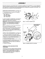
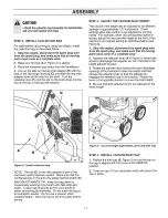
Page 8: ...nlet cap for the optional vacuum hose is located on the front of the machine The discharge opening is at the rear The left and right sides are determined by standing at the rear of the machine when the handlebars are in the vacuum position UNFOLD THE HANDLEBARS see Figure 2 1 Squeeze the handlebar end with decal Push in Here toward the center of the machine to release end from the notch in the mou...

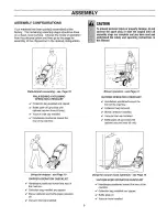
Page 9: ...Baffle plate off provided with optiona vacuum hose kit only V Vacuum inlet cap installed v Handlebars positioned toward the rear of the machine Blower operation see Page 12 BLOWER OPERATION CHECKLIST v Handlebars positioned toward the front of the machine v Collection bag removed v Blower deflector installed v Vacuum inlet cap installed v Baffle plate off provided with optional vacuum hose kit onl...

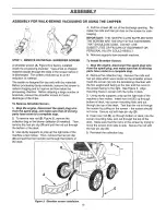
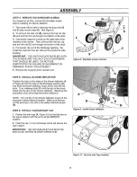
Page 10: ...tall the rods and hair pin clips on the screen for safe keeping IMPORTANT THE HAIR PIN CLIPS SUPPLIED WITH THE SCREEN ARE THE ONLY STYLE FASTENERS THAT SHOULD BE USED DO NOT USE SUBSTITUTES OR FAILURE OF EQUIPMENT OR PERSONAL INJURY COULD RESULT 5 Remove supports from beneath machine_ To Install Shredder Screen 1o Stop the engine disconnect the spark plug wire from the spark plug and make sure tha...

Page 11: ...Allow the bag to dry thoroughly before storing STEP 3 ADJUST THE VACUUM INLET HEIGHT The vacuum inlet height can be adjusted to six different settings in approximately 1 2 increments These settings allow inlet suction to be adjusted for varying needs For example when vacuuming deep layers of leaves adjust the vacuum inlet height at the front of the machine to its highest setting as described below...

Page 12: ...d make sure that all moving parts have come to a complete stop 2_ Pull and then turn the retaining knob F in Figure 6 so that it clears the edge of the bag inlet adapter B and the tab rests on the upper housing_ Grasp the pull strap and slide the bag inlet adapter B out of the slots in the discharge opening C 3 Hold the collection bag A with the inlet opening upright so that material does not fall...

Page 13: ...OULD RESULT 5 Remove the supports from beneath unit STEP 5 INSTALL BLOWER DEFLECTOR Position the tabs on the sides of the blower deflector A in Figure 9 into the slots in the discharge opening B and slide the blower deflector down all the way into the slots Turn retaining knob D until the tab on the knob drops into the slot on the blower deflector Reverse this procedure when removing the blower de...

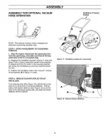
Page 14: ...chine to release end from the notch in the mounting bracket and swing the handlebars up over the machine toward the rear 3 Position the handlebar ends in the vacuum notches of the brackets B in Figure 11 inset r STEP 2 REMOVE BLOWER DEFLECTOR IF INSTALLED Turn retaining knob D in Figure 12 until the tab on the knob is out of the slot in the blower deflector Pull the sides of the blower deflector A...

Page 15: ...3 Shredder screen removal STEP 4 INSTALL COLLECTION BAG CAUTiOR Check the collection bag frequently for deteriorationand wear and replaceworn hags For using the vacuum hose install the collection bag as described below 1 Make sure the bag A in Figure 14 is zipped 2 Place the collection bag straps over the handlebars 3 Line up the tabs on the bag inlet adapter B with the slots in the discharge open...

Page 16: ...REMOVE VACUUM INLET CAP AND INSTALL HOSE 1_ Remove the vacuum inlet cap A Figure 16 by twisting the cap counterclockwise approximately I 4 turn until the bar on the cap is aligned with the arrow at the REMOVE position_ Lift the cap off the inlet opening Do not misplace the vacuum inlet cap 2 Line up the tabs on the hose B with the slots in the vacuum inlet opening and insert the hose Turn the hose...

Page 17: ...to process small branches F FUELTANK Stores engine fuel G RECOIL STARTER ROPE Used to start the engine_ H BLOWER DEFLECTOR Directs air flow when machine is used in blower configuration I SAFETY INTERLOCK ROD Part of the safety interlock system which stops the engine if either the collection bag or blower deflector is not installed J VACUUM HOSE OPTIONAL Used for remote vacuuming K BAFFLE PLATE Use...

Page 18: ...stall dipstick screw dipstick down securely to check oil level Wipe dipstick with a clean cloth before reinserting each time Fill to the FULL mark on dipstick DO NOT OVERFILL 5 Reinstall the dipstick securely A STEP 2 ADD GASOLINE TO THE FUEL TANK Fill the fuel tank with fresh clean unleaded regular automotive gasoline Leaded regular and un eaded premium grades of gasoline are acceptable substitut...

Page 19: ...he spark plug wire before starting the engine SAFETYINTERLOCK SYSTEM Your machine is equipped with a Safety Interlock System which prevents the engine from starting unless the collection bag or blower deflector is installed The rod A Figure 20 must be positioned as shown in slot B in order to start the engine The system also stops the engine if the operator attempts to remove the bag or blower def...

Page 20: ... is not required when starting an engine which has already run for a few minutes 4 Stand at the left front of the machine Place one foot against left front wheel to stabilize the machine 5 Look behind you to make sure there are no obstacles in the way Grasp the Starter Rope Handle C and pull handle quickly Do not alfow starter rope to snap back NOTE In cool weather repeat pfimimg step if necessary...

Page 21: ...hrough the discharge opening into the collection bag VACUUMING AND CHIPPING GUIDE The chart below lists some commonly available materials that can be processed using your ChipperNac This chart is only intended as a general guideline For complete vacuuming and chipping operating instructions please read this entire Operation Section MATERIAL L Dryleaves Dampleaves Acorns pineneedles Grassclippings ...

Page 22: ... matted down over the 3receding months For best results when vacuuming this type of debris remove the screen lower the vacuum inlet and walk slowly You can even use the machine as you would a vacuum cleaner moving it back and forth over particularly stubborn debris or loosen the debris with a few quick passes of a rake and then vacuum Fall Operation Don t try to vacuum too much at one time Optimum...

Page 23: ...rotate when the engine starts and slow down gradually after the engine is shut off Do notallow hands or any olher part of the body or clothing inside the vacuum hose opening blower dischargeopening chipper chute or near any movingpart Before inspecting cleaning or servicing the machine stop the engine and make sure that all moving parts have come to a complete stop Disconnect the spark plug wire a...

Page 24: ...low down gradually after the engine is shut off Do not allow hands or any other part of the body or clothing inside the vacuum hose opening blower dischargeopening chipper chute or near any movingpart Before inspecting cleaning or servicing the machine stop the engine and make sure that all moving parts have come to a complete stop Disconnect the spark plug wire and secure it away fromthe sparkplu...

Page 25: ...r operation 3 Guide the branch down until your hands approach the top of the chute Note that there is a flap at the top of the chipper chute NEVER PUT YOUR HANDS DOWN PAST THE CHIPPER CHUTE FLAP iMPORTANT DO NOT OPERATE THE CHIPPER iF THE CHIPPER FLAP IS WORN OR MISSING 4 Feed the branch slowty If the machine labors puil the branch upward until the engine regains speed Continue to alternately feed...

Page 26: ...o stop Disconnect the spark plug wire and secure it away from the spark plug 2 Check and clean if necessary the following areas in the order given_ For all vacuuming operations 1 Check that the collection bag is not overfilled 2 While the bag is removed check that the discharge opening is not clogged For walk behind vacuuming 1 Check that the vacuum inlet opening is not clogged 2 Use a stick to cl...

Page 27: ...ration NOTE 2 Servicemorefrequentlyin extremely dustyor dirbjconditions NOTE 3 If engineis equipped witha sparkarrestor cleanandinspectfor damageevery50operatinghours NOTE 4 Replace yearlyor mereoften if usedinextremely dustyor dirtyconditions CHECK AND CHANGE ENGINE OIL Q Check oil level every five operating hours and before each use of the machine_ Q Change oil after first two hours of new opera...

Page 28: ...ERVICE THE AIR FILTER The engine is equipped with a paper element air filter_ See Figure 28 IMPORTANT NEVER RUN ENGINE WITHOUT COMPLETE AIR FILTER ASSEMBLY INSTALLED REPLACE FILTER ONCE A YEAR OR MORE OFTEN IF USED IN EXTREMELY DUSTY OR DIRTY CONDITIONS DO NOT ATTEMPT TO CLEAN OR OIL FILTER o REPLACEMENT FILTERS ARE AVAILABLE FROM ANY SEARS ROEBUCK AND CO OR SEARS CANADA INC SERVICE CENTER To Repl...

Page 29: ...condenser Only spark plug maintenance is required If the ignition system is not functioning properly contact your local Sears Service Center or retail store Electrodes 030 Gap Porcelain Figure 30 Spark plugo CHECK BOLTS AND NUTS FOR TIGHTNESS Be sure that the bolts and nuts on your machine are always securely tightened With the engine shut off and the spark plug wire disconnected check the bolts a...

Page 30: ...ank DANSER Gasoline and its vapors are highly flammable and explosive To avoid serious personal injury be sure area is well ventilated and keep gasoline away from open flame or sparks Observeno smoking rules at atl times_ Use an approvedfuel conlainer b Using adjustable pliers squeeze the tabs on the hose clamp A in Figure 31 that secures the fuel line B to the fuel tank fitting Slide the clamp a ...

Page 31: ...t Tighten securely torque to 240 lbs in or 20 Ibs ft 11 Place key F in the engine crankshaft and re install any shims G Align the keyway in the bore with the key on the crankshaft and slide the flywheel assembly into place 12 Place the concave washer E dished in side of washer faces flywheel assembly on the mounting bolt D and install the bolt in the crankshaft Tighten securely torque to 204 Ibs i...

Page 32: ... Craftsman Fuel Stabilizer No 335500 may be added to any gasoline left in the tank to minimize gum deposits and acids If the tank is almost empty mix the stabilizer with fresh gasoline in a separate container and add some to the tank ALWAYS FOLLOW INSTRUCTIONS ON THE STABILIZER CONTAINER THEN RUN THE ENGINE AT LEAST 10 MINUTES AFTER THE STABILIZER IS ADDED TO ALLOW MIXTURE TO REACH CARBURETOR STOR...

Page 33: ... Solidobjectjammed in unit 2 Brokenor missingchipperblade I LDull chipper blade 2 Enginenot reaching full RPM 3 Excessivelyworn engine shaft bearing s 4 Loose engine mounting bolts 5 Chipper blade to anvil clearance incorrect CORRECTION 1 Reconnectwire 2 Put EngineControl Lever in START Page 20 3 Add gasoline Page 19 4 Drain gasoline and add fresh gasoline 5 Contact SearsService Center 6 Install c...

Page 34: ...rcrankshaftisbent 5 or damaged 6 Looseenginemountingbofts 6 7 Looseor m ssingboltsonunit 7 8 Engine shaftbearingsdamaged 8 CORRECTION Checkfor andremoveanyobstruction Page 26 Remove andemptybag Page12 Remove collectionbagto clean opening Page12 Check for andremove any obstruction Page26 See Engine RunsPoorly at beginning of chart Checkfor andremove anyobstruction SeePage 26 Tightenor replace Page ...

Page 35: ...NOTOPERATE tF SAFETYINTERLOCK IS BROKEN OR BECOMESDEFECTIVE SEE OWNER OPERATOR _ MANUAL __ i ROTATING CUTTINGBLADESWILL CAUSESERIOUSINJURYf INLET CAP ORHOSE MUSTBEINSTALLED DISCHARGE OPENING TOAVOIDSERIOUS INJURY HOT SURFACES CAN CAUSE SEVERE BURNS DO NOTTOUCH MUFFLEROR ADJACENT AREAS ROTATINGCUMNG BLADE WILL CAUSE SERIOUS INJURY n KEEP HANDS OUT OF CHIPPER CHUTE INLET AT ALL TIMES 35 ...

Page 36: ...CRAFTSMAI 5 HP CHIPPER VACMODELNUMBER987 799601 REPAIRPARTS 89 _ 4O 57 t 12 i I I t I 8 i I I o i 65 36 ...

Page 37: ... 1761627 60 1763393 61 1763392 62 1186259 63 1737499 64 1100047 65 1893445 66 1107383 67 1733398 79 1764076 80 1756986 83 1764649 86 1186309 87 1734398 88 1728401 89 1765507 96 1769136001 97 1768703 98 1768655 99 1185748 100 1769123 101 1115958 200 1769635 201 1769649 205 1769633 206 1769654 207 1769637 208 1767298 209 1902079 b 1902963 Goggles t HoseCapInlet 1 HeightAdjusting Lever 2 WheelHeightA...

Page 38: ...CRAFTSMAN4 CYCLEENGINE MODELNO 143 955002 276 _ 277 A _ _ _ _ 400 130 135 120 MODELandSERIALIZe NUMBERSHERE 11287 370 260 262 119 125 126 7 301 292 29O I_ _ 292 7 241_ 38 ...

Page 39: ...r Head Gasket Cylinder Head Exhaust Valve Std lncL 151 Exhaust Valve 1 32 OS ncl 151 intake Valve Std lncL 151 Intake Valve 1 32 OS Inc 151 Screw 5 16 18 x 1 1 2 Resistor Spark Plug RJ19LM tef 150 t51 169 172 174 178 t79 182 184 185 186 200 202 203 204 205 206 207 2O9 215 223 224 238 239 241 245 25O 260 261 262 275 _75A 276 277 __77t 285 287 290 292 300 301 306 306 307 309 310 313 327 370 370 38O ...

Page 40: ...r Bulb Filter High Speed Bow Nut Bowl Nut Washer Welch Plug Atmospheric Vent HOSEKIT NO 987 856790 Fig 3 Part Noo Part Name Ref INo U 1767377 1765866 1763291 1763281001 1756875 1763283001 1740083 tlO0123 1186389 1107381 Hose Tube Hose Adapter Handle Handle Grip Inlet Cover Worm Clamp SLotted Head Screw I 4 20 x 1 1 4 Flange Whiz Locknut 1 4 20 Washer REWINDSTARTERNO 590732 Fig 2 Ref No 1 2 3 4 5 6...

Page 41: ...NOTES 41 ...

Page 42: ...NOTES 42 ...

Page 43: ...NOTES 43 ...

Page 44: ... engine s blower housing above the spark plug All parts listed herein may be ordered through Sears Roebuck and Co Service Centers and most Retail Stores WHEN ORDERING REPAIR PARTS ALWAYS GIVE THE FOLLOWING INFORMATION PRODUCT CHIPPERNAC MODEL NUMBER 987 799601 ENGINE MODEL NUMBER 143 955002 PART NUMBER PART DESCRIPTION Your Sears merchandise has added value when you consider that Sears has service...

Reviews: