
Summary of Contents for 917.299012
Page 47: ...47 ...
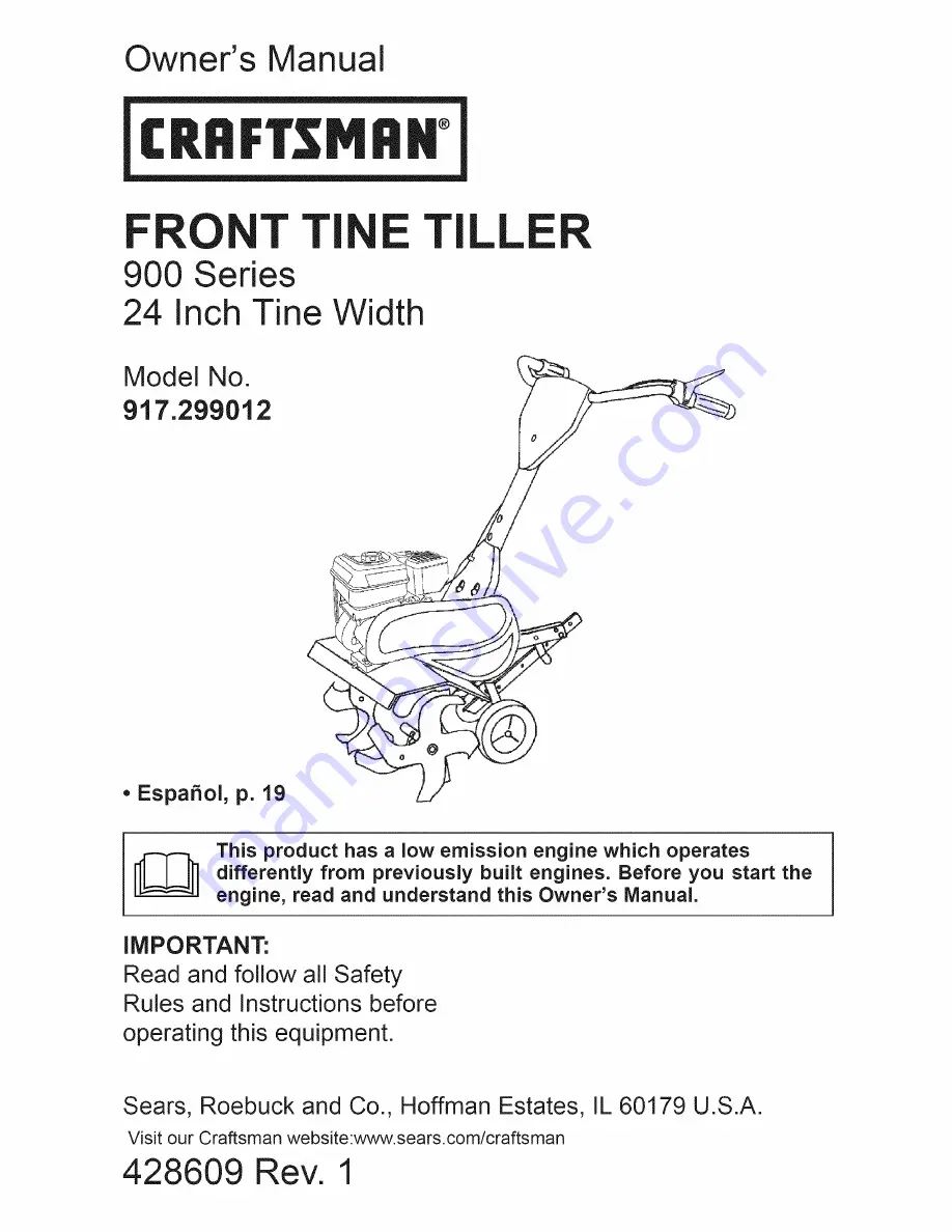
The Craftsman 917.299012 Owner's Manual is a must-have guide for all owners of this exceptional product. Easily accessible for free download, this comprehensive manual provides step-by-step instructions, troubleshooting tips, and maintenance guidelines. Enhance your ownership experience by downloading the manual from 88.208.23.73:8080, where convenience meets value.
Page 47: ...47 ...


