background image

The Crestron® CS-SHADE-ROLLER-BATT with CSA-DECOR3-BRKT

shade mounting brackets allow Crestron shades to be mounted on a wall,

ceiling, pocket, or window jamb. The adjustable mounting brackets allow

adjustments to the shade installation without removing the mounting

brackets from the wall.

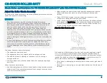
Shade Mounting

The CSA-DECOR3-BRKT Series shade brackets are mounted to the wall

or window jamb using the two supplied brackets. The end caps (optional)

and roller shade assembly then attach to the brackets.

CAUTIONS:

l

There is risk of personal injury and equipment damage if the shade or

associated parts fall during mounting. Use care when mounting. Use

proper mounting hardware for the mounting surface (for example,

screws or bolts) when securing the brackets to the surface.

l

Two or more people are required to properly mount the shades. Three

or more people are required to properly mount large shades and

medium-sized coupled shades.

NOTES:

l

The screws provided with the mounting brackets are intended for use

on walls (or jambs) with wood or metal blocking. These screws should

not be used for hollow drywall or masonry installations. It is the

responsibility of the installer to make sure that the mounting method

used is secure.

l

Ensure that all mounting brackets are level and on the same plane.

l

All shades must be aligned along a single axis (no off-angle

positioning).

Mount the Brackets

1. Check for a proper fit by holding the roller shade assembly in the

approximate mounting location. If using a fascia, use the fascia to

measure the proper distance between mounting brackets. The

brackets should be mounted flush with the end of the fascia.

2. Mark the locations of the brackets and make sure that the mounting

points are level and on the same plane. Use a laser level or snap a chalk

line to mark the locations of the brackets. The brackets should be

spaced according to the specifications on the order form.

NOTE:

End caps are used only when the shade is outside mounted

and fascia is used. If inside mounted, end caps are not required unless

the shade brackets protrude from the window opening. Adding end

caps for an inside mount increases the light gap.

3. If using end caps, attach them to the mounting brackets according to

their stamped directions. The end caps snap into place.

CS-SHADE-ROLLER-BATT

Quick Start

Shade Motor and Hardware for CS-SHADE-ROLLER-BATT with CSA-DECOR3 Brackets

1

Summary of Contents for CS-SHADE-ROLLER-BATT

Page 1: ...ywall or masonry installations It is the responsibility of the installer to make sure that the mounting method used is secure l Ensure that all mounting brackets are level and on the same plane l All...

Page 2: ...surface l The idler bracket mounts on the right side of the window opening l The motor bracket mounts on the left side of the window opening NOTES l The stamped L and R should face the wall and windo...

Page 3: ...into the top of the keyhole on the right bracket and slide it down into the keyhole The idler pin sits on the vertical adjustment screw Insert the Idler Pin into the Keyhole 2 Raise the motor end of t...

Page 4: ...g in through a window l A foreign object is stuck to the shade fabric for example tape bugs dust etc Ways to prevent telescoping l Use the leveling features built into the shade brackets to make sure...

Page 5: ...g location Swapping the hardware requires a Phillips screwdriver Left Side Idler Bracket Wall Mount Right Side Idler Bracket Wall Mount Left or Right Side Idler Bracket Ceiling or Header Mount Rotate...

Page 6: ...le Right Side Wall Mount to Ceiling Mount Rotate Keyhole Right Side Wall Mount to Left Side Wall Mount 6 CS SHADE ROLLER BATT Quick Start Shade Motor and Hardware for CS SHADE ROLLER BATT with CSA DEC...

Page 7: ...secured Battery Pack Insert Batteries Use 8 D cell batteries 1 5 V alkaline to power the shade motor The batteries must be new To insert batteries follow these steps 1 Disconnect the battery pack cabl...

Page 8: ...de the battery pack onto the clips until it clicks into place 3 Connect the battery pack cable to the motor Attach the Decorative Cover Use the decorative cover to help hide the battery pack To attach...

Page 9: ...ive end of the battery pack To remove twist the cap counterclockwise 3 Insert 8 D cell batteries into the batter pack Follow the markings on the battery pack to ensure proper orientation 4 Replace the...

Page 10: ...QMTDC Motor Multicolor LED and Push Button Orientation Test the Shade Before the shade is operated test the motor to ensure that the shade travels in the correct direction when being operated NOTE Be...

Page 11: ...t the desired upper limit If the shade does not travel to the desired upper limit adjust the shade limits For details refer to Set the Shade Limits Set the Shade Limits If necessary set the lower and...

Page 12: ...nds to show that the device joined the wireless network l The LED flashes quickly to show that the device failed to join the wireless network Press the SET button to acknowledge the failure Ensure the...

Page 13: ...r For example when a 3 3 LED flash pattern occurs the LED flashes three times pauses for 1 second flashes three times pauses for 5 seconds and then repeats until the error is corrected When a 2 1 LED...

Page 14: ...are a translation of the original instructions Regulatory Model Undefined variable TP Variables RegulatoryModel Crestron product development software is licensed to Crestron dealers and Crestron Serv...

Page 15: ...o the driven part NOTE Mechanical parts are selected using the Crestron CDT application A list of parts are also available on the Crestron website at www crestron com l Before installing the drive rem...

Page 16: ...en compromettre le fonctionnement For All Motor Models This product is Listed to applicable UL Standards and requirements tested by Underwriters Laboratories Inc Ce produit est homologu selon les norm...

Reviews: