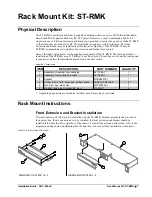
Rack Mount Kit: ST-RMK
Physical Description
The ST-RMK is a rack mount kit that is capable of holding either one or two CEN Ethernet Modules,
SmarTouch STS Expansion Modules, ST-CP Control Processors, or any combination of units in a
single rack space. The front extrusion and bracket are provided to occupy the open bay of the ST-RMK
so that when only one module (or ST-CP) is installed, no gaps are visible in the rack. The front
extrusion and bracket may be installed in either the left or right bay of the ST-RMK. When the
ST-RMK accommodates two modules, the extrusion and bracket are not used.
Items 1 through 6 listed below are the supplied components of the ST-RMK. The tools required for
installation of the ST-RMK are a #1 Phillips 1/4-inch hex bit, a 1/4-inch hex socket, and an inch-pound
torque driver. Follow the installation procedures in the next section.
Supplied Components
ITEM
DESCRIPTION
PART NUMBER
QUANTITY
1
Assembly, chassis & front extrusion
AY17489-1
1
2
Assembly, front extrusion & label
AY17490-1
1*
3
Bracket
MTBK02315-1
1*
4
Screw, 4-40 x 1/4"L, steel, pan, phillips, black
SR04-40-0R2500-8
8*
5
Nut, 4-40, hex, steel, zinc
MTPL02390-1
4
6
Washer, lock, steel, internal, #4, zinc
WA04L0-1
4
* D
epending upon number of modules installed, not all items may be required.
Rack Mount Instructions
Front Extrusion and Bracket Installation
If two modules (or ST-CPs) are to be installed onto the ST-RMK, skip this procedure and proceed to
the next section. If only one module is to be installed, the front extrusion and bracket should be
installed into either the left or right bay of the chassis. To install the extrusion and bracket, refer to the
diagrams and steps below (installation into the right bay is shown, left bay installation is identical).
Install Front Extrusion & Bracket
2
3
6
5
4
1
3
DIAGRAM FOR STEPS 1 & 2
DIAGRAM FOR STEPS 3 - 6
X 4
X 2
Installation Guide - DOC. 5664A
Rack Mount Kit: ST-RMK
•
1


