


Summary of Contents for EOe-1
Page 1: ...USER MANUAL EOe 1 10 100Base Ethernet over G 703 Unframed E1 ...
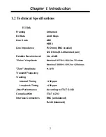
Page 2: ......
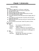
Page 4: ......
Page 18: ...Chapter 1 Introduction 12 This page left blank intentionally ...
Page 26: ...Chapter 2 Installation 20 This page left blank intentionally ...
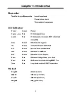
Page 43: ......


