background image

USER MANUAL

MULTILINGUAL  
MANUAL

CHARGESTORM® CONNECTED 2

Summary of Contents for CHARGESTORM CONNECTED 2

Page 1: ...USER MANUAL MULTILINGUAL MANUAL CHARGESTORM CONNECTED2 ...

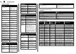
Page 2: ...onnector for variants with fixed cable 6 Insulation tube 7 Four mounting screws 8 Four rubber gaskets 9 Four metal gaskets 10 Jumper for variants with one phase Overview 1 2 3 4 5 6 1 Front panel 2 Display with charging status symbols Overcurrent and short circuit protection 10 Part specific data 10 CTEK E Mobility warranty statement 11 Limited warranty 11 Circumstances that will void the limited ...

Page 3: ... Flashing Blue RFID Open Charging in progress SYMBOL COLOR MODE EXPLANATION Solid Red RFID Open Alarm active Most likely a fuse has tripped Open the technical box and reset the fuse Outlet has a temporary fault The fault could be one of the following Time limit for authentication reached PP signal cannot be read from cable Only applicable for type 2 outlet Outlet motor could not lock cable Solid B...

Page 4: ...rging station RFID access means that the charging does not start until a RFID tag has been used for authentication Some operators also offers additional authentication such as a mobile app NOTE There are many different RFID formats Contact CTEK E Mobility if your RFID tags are not original CTEK E Mobility RFID tags to make sure that your RFID tags are compatible with the charging station The suppo...

Page 5: ...s that follow before you do the cable installation 1 Avoid installation of the EV charger in direct sunlight If the product is installed in direct sunlight symbol visibility is decreased and the temperature of the product increases This will trigger the overheating protection and limiting the charging current 2 Decide if the unit should be installed outdoors or indoors a For outdoor installation t...

Page 6: ... connected NOTE For regional differences of the grounding system such as IT Nett refer to the supply input schematic on page 13 To install the charging station on a pole For installation on a pole refer to the manual for the pole mount kit To do the cable installation 1 Make sure that the power is off A A 16 mm2 2 Make sure that the cable installation is dimensioned A for the charging station CAUT...

Page 7: ...upgrades If Ethernet shall be connected use a network cable of type Cat5 or better Connect the network cable to the RJ45 connector on the control board The control board is located on the front panel When the network cable is connected the activity LED in the RJ45 connector activates Mini SIM 15x25mm If 3G shall be connected install an activated SIM card in the charging station The PIN must be dis...

Page 8: ... the controller board 3 Open the web browser and log in to the local web interface at http 192 168 7 2 The user name and password are both ccu NOTE CTEK E Mobility recommends web browser Chrome for this action To configure the network interface Ethernet 2 3 4 1 5 1 Navigate to Configuration Interface General and select WAN Wire 2 Navigate to Configuration Interface 3 Select Wire 4 Select DHCP or S...

Page 9: ...age 7 Navigate to the status page and verify that the portal communication is established To configure RFID 2 3 1 NOTE For chargers without portal connection you can only add and remove RFID tags from the web interface in the charger For connected chargers you can only change in the portal 1 Navigate to Configuration Outlet Authentication and select RFID for all outlets to activate RFID authentica...

Page 10: ... GSM GPRS EDGE 900 MHz Max 2W 1800 MHz Max 1W COMPATIBILITY Compliance IEC 61851 1 IEC 62196 2 IEC 61439 7 CE Approval Download the Declaration of Conformity from www ctekemobility com Charging method Mode 3 Electric shock protection Class I equipment Communication protocol OCPP 1 5 and 1 6 Pollution degree 3 Intended for use in EMC Environment B SAFETY Ground fault detection Residual Current Devi...

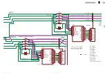
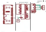
Page 11: ...figuration Protocol OCL Outlet Controller Light OCPP Open Charge Point Protocol PP Proximity Pilot PPP Point to Point Protocol RFID Radio Frequency Identification WWAN Wireless Wide Area Network Electrical schematics 01 A 11 01 B 12 01 C 13 CCU 14 3G RADIO MODEM 14 CAB10 14 3PH OUTLET LEFT 15 1PH OUTLET LEFT 15 3PH CABLE LEFT 15 1PH CABLE LEFT 16 3PH OUTLET RIGHT 16 1PH OUTLET RIGHT 16 3PH CABLE R...

Page 12: ...ferrules here EM1 EM2 X6 X7 X8 X1 X1 X2 X2 X3 X3 X4 X4 F1 F2 U3C U4C 1 2 3 4 5 6 L1 L2 L3 1 2 3 4 5 6 N N L1 L2 L3 1 2 3 4 5 6 N N 1 2 3 4 5 6 1U 2U 3U 4U 5U 6U 2L 4L 6L 1L 3L 5L 1U 2U 3U 4U 5U 6U 2L 4L 6L 1L 3L 5L 1 2 J302 3 4 5 L1P 6 L1N L2P L2N L3P L3N 1 2 J302 3 4 5 L1P 6 L1N L2P L2N L3P L3N Optional Optional Optional Optional Heater Optional Choose one of two options Energy Meter X15 EM1 W11 ...

Page 13: ...ST ERR X6 X30 GND VCC PWM NC LOW HIGH 4 5 6 FUSE_FB RELAY_OUT NEUTRAL L1_IN L2_IN L3_IN 1 2 J301 3 1 2 3 4 5 6 7 8 9 10 J502 TEST ERR X6 X30 GND VCC PWM NC LOW HIGH 4 5 6 FUSE_FB RELAY_OUT NEUTRAL L1_IN L2_IN L3_IN 1 2 3 4 5 6 1 2 3 4 5 6 1 2 J1001 TEST 3 4 5 6 7 8 ERR X6 X30 GND VCC PWM NC 1 2 J1001 TEST 3 4 5 6 7 8 ERR X6 X30 GND VCC PWM NC Phase rotation See next page See next page Used by Dual...

Page 14: ... is replaced by the external cable U2 P1 EM1A EM2A U1A X5 U4B U3B 1 2 1 2 K1 3 4 L N PE 1 2 K2 1 2 K3 AC DC 24 230 1 2 1 2 3 4 3 4 2 1 3 4 2 1 3 4 2 1 3 4 2 1 3 4 2 1 A B GND 9 8 10 7 T 120R A B GND 9 8 10 7 T 120R 1 2 1 2 B2 A2 1 2 J6 1 2 GND J29 24V RTN B A 4 3 J305 24V 1 2 4 3 2 1 4 3 1 2 A B J304 J306 ADDR B A 4 3 J305 24V 1 2 4 3 2 1 4 3 1 2 A B J304 J306 ADDR EARTH Used by Dual output models...

Page 15: ...RD2 GN2 BU2 RD1 GN1 BU1 J32 J31 J33 J23 J24 J5 J6 J4 J30 J7 J8 J1 J3 J2 J29 J16 J17 J18 J19 J20 J21 J22 J25 J26 J12 J13 J27 J28 J15 J14 J11 RFID1 RFID2 J5 J6 RFID RS485 RS485 RS485 GCU STATION CCU 1v98 higher CCU CCU CCU Modem U FL Antenna CAB18 U1C U1D U8 P11 U9 1 2 JP4 3 4 24V GND 1 2 JP2 GND 3V3 1 2 JP9 GND 3V3 1 2 JP7 3 4 JP3 5 6 7 8 9 10 1 2 3 4 5 6 7 M_TX M_RX 3V3 HDPB HDMB M_RESET ON OFF SC...

Page 16: ...6 7 8 CP PP GND GND SOL LOW SOL SENS 12V 12V 3PH OUTLET LEFT Lock Solenoid Outlet OCL Left CAB8 L1 N X11 W22 BK 6 W25 BU 6 M1 OUT1 U3D W41 YEGN 6 1 2 3 4 5 6 7 8 L1 L2 L3 N PE CP PP 1 2 J503 3 4 5 6 7 8 CP PP GND GND SOL LOW SOL SENS 12V 12V 1PH OUTLET LEFT Cable OCL Left L1 L2 L3 N OUT1 X11 U3D CAB15 X13 L1 L2 L3 N PE CP 1 2 3 4 5 6 7 8 1 2 J503 3 4 5 6 7 8 CP PP GND GND SOL LOW SOL SENS 12V 12V ...

Page 17: ...id Outlet OCL Right CAB9 L1 L2 L3 N W37 BK 6 W38 BK 6 W39 BK 6 W40 BU 6 W42 YEGN 6 U4D X12 M2 OUT2 1 2 3 4 5 6 7 8 L1 L2 L3 N PE CP PP 1 2 J503 3 4 5 6 7 8 CP PP GND GND SOL LOW SOL SENS 12V 12V 3PH OUTLET RIGHT Lock Solenoid Outlet OCL Right CAB9 L1 N X12 W37 BK 6 W40 BU 6 M2 OUT2 U4D W42 YEGN 6 1 2 3 4 5 6 7 8 L1 L2 L3 N PE CP PP 1 2 J503 3 4 5 6 7 8 CP PP GND GND SOL LOW SOL SENS 12V 12V 1PH OU...

Page 18: ... LOW SOL SENS 12V 12V 3PH CABLE RIGHT Cable OCL Right L1 N OUT2 X12 U4D CAB16 X14 L1 L2 L3 N PE CP 1 2 3 4 5 6 7 8 1 2 J503 3 4 5 6 7 8 CP PP GND GND SOL LOW SOL SENS 12V 12V 1PH CABLE RIGHT U3 U4 J501 J306 J305 J502 J503 J304 J301 6 5 4 3 2 1 J302 OCL L3_IN L2_IN L1_IN NEUTRAL RELAY_OUT FUSE_FB Current Trafos Address Termination EV Outlet 2 X Mod Pwr VAC Sensor Fail SW OCL ...

Page 19: ...WWW CTEKEMOBILITY COM 50022553 ...

Reviews: