background image

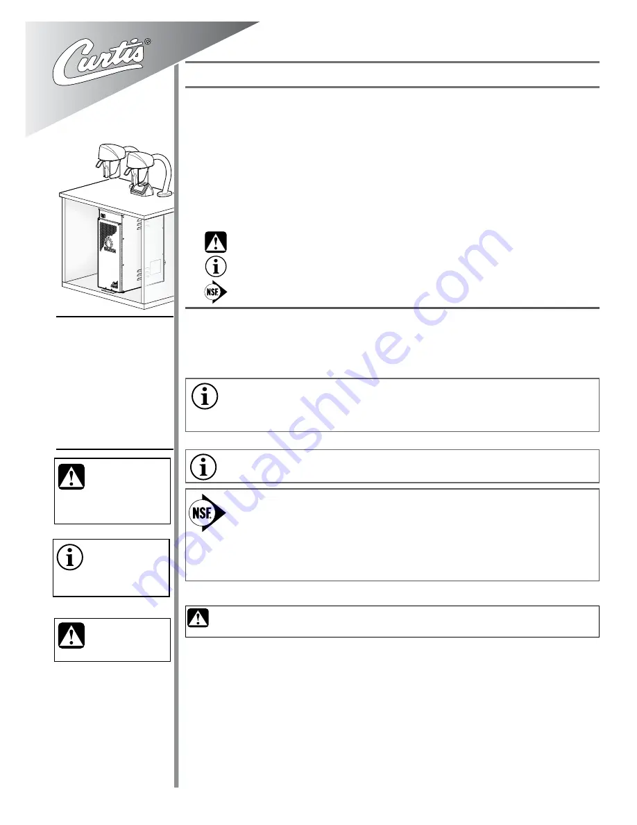
The Curtis G4 brewer is preset at the factory for optimal performance.

Following are the factory settings for the G4 Coffee Brewing System:


• Brew Temperature = 200°F  • Brew Volume = Set to vessel requirement.

System Requirements:


• Water Source   20 – 90 psi (138 – 620 kPA) with a minimum flow rate of 2 gpm (7.5 lpm). 


• Electrical: See attached schematic for standard model or visit www.wilburcurtis.com for your model.

INSTALLATION INSTRUCTIONS

Please adhere to these installation instructions to ensure proper set up.

Confirm that the planned location for the coffee brewer has the proper electric and water supply. In 

addition, water drain pipes and the floor stability should be considered.
The water tower should be installed and grounded properly by a qualified installer or service 

technician. This unit must be electrically grounded in accordance with local codes.
Carefully unpack the Seraphim brewer components from the shipping crates.

    continued...

1

Models: 

  SERA2B, SERA2W, 

SERA2W330033, 

SERA2B330033, 

SERA2B30, 


SERA2W30, 


SERA2B33,  


SERA2W33, 


SERA2B300293, 

SERA2W300293

CAUTION:

 DO NOT 

connect this brewer to hot 

water. The inlet valve is 

not rated for hot water.

CAUTION:

 Use this setup 

procedure before attempt-

ing to use this brewer. 

Failure to follow the instructions can 

result in personal injury or void the 

warranty.

IMPORTANT:

 Equipment 

to be installed to comply 

with applicable govern-

mental plumbing/electrical codes 

having jurisdiction.

ISO 9001:2008 REGISTERED

WILBUR CURTIS CO., INC.

6913 Acco Street

  Montebello, CA 90640-5403

For the latest information go to 

www.wilburcurtis.com

Tel: 800-421-6150

Fax: 323-837-2410

This equipment is designed for commercial use. Any servicing other than cleaning and routine maintenance 

should be performed by an authorized Wilbur Curtis Co., Inc. service technician.
  •   DO NOT immerse the unit in water or any other liquid.

  •   To reduce the risk of fire or electric shock, DO NOT open service panels. There are no user serviceable  

    parts inside. 
  •   Keep hands and other items away from hot areas of the unit during operation.
  •   Never clean with scouring powders or harsh chemicals.

Important Safeguards/Symbols

Service Manual – Seraphim Coffee Brewer

W

ilbur

 C

urtis

 C

o

., i

nC

.

NSF International requires the following water connection:

1.  A quick disconnect or additional coiled tubing (at least 2x the depth of the unit) is required so 

that the unit can be moved for cleaning.

2.  This brewer must be installed with adequate back-flow protection to comply with applicable 

federal, state and local codes.

3.  Water pipe connections and fixtures directly connected to a potable water supply shall be 

sized, installed and maintained in accordance with federal, state and local codes.

NOTE:

 Electrical source should have a minimum 30 A internal common trip circuit breaker between 

the brewer and the main supply, which breaks all poles with a contact separation of at least 3 mm. 

NOTE:

 A water filtration system must be used to help maintain trouble-free operation. 

Air must be 

purged from the cartridge prior to connection to equipment. 

In areas with extremely hard water, 

we highly recommend the use of a Curtis approved water filter. For our full line of filters, please visit       

www.wilburcurtis.com. 

Symbols:

WARNING

/

CAUTION

 – To advise about conditions that may result in property damage, 

personal injury or death

IMPORTANT

 – Notes about proper operation

Sanitation requirements

CAUTION: Avoid Injury.

 Do not turn on water or electricity until the brew head and water tower 

assemblies are properly installed.

Summary of Contents for SERA2B

Page 1: ... use Any servicing other than cleaning and routine maintenance should be performed by an authorized Wilbur Curtis Co Inc service technician DO NOT immerse the unit in water or any other liquid To reduce the risk of fire or electric shock DO NOT open service panels There are no user serviceable parts inside Keep hands and other items away from hot areas of the unit during operation Never clean with...

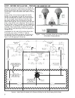
Page 2: ...le Consideration must be made for the drip tray drain system The drip tray comes with a 1 2 NPT X 3 nipple for connecting the drain system supplied by the purchaser to the drain fitting located on the bottom of the drip tray See Figure 3 on the facing page for dimensions 2 WATER HEATER LEFT BREW HEAD RIGHT BREW HEAD UCM TOUCH SCREEN COUNTERTOP Figure 1 Cabinet Installation Showing Four Main Sectio...

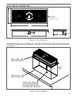
Page 3: ... the drip tray pieces as shown in Figure 4 and place them into position Install the drain system 3 Figure 3 Drip Tray Dimensions Figure 4 Drip Tray Installation INSET FRAME INSET INSTALLATIONS ONLY INSET CUTOUT INSET INSTALLATIONS ONLY DRAIN HOLE FOR FLUSH INSTALLATIONS OR INSET INSTALLATIONS THAT ARE ENCLOSED ON THE BOTTOM 3 4 1 INSET FRAME REMOVE FOR FLUSH INSTALLATION 20 1 4 ø1 125 8 3 4 21 3 4...

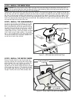
Page 4: ...ther brew head STEP 4 INSTALL THE UCM ASSEMBLY Locate the wiring harness and UCM plugs coming from behind the water tower Plug the touch screen wiring harness and USB wiring into the receptacles in back of the UCM These will snap and lock into place Install the UCM holder onto the counter top Slip the two 1 4 20 threaded studs into the counter top and fasten the holder to the Counter using 1 fende...

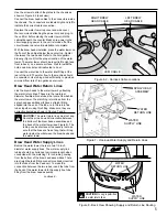
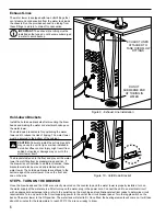
Page 5: ...tubes that come from behind the water tower The matching return lines from the spray head assemblies will have a straight fitting slipped into the end of the tube Join the return line tubes together using this fitting Make sure they are correctly oriented as shown in Figures 7 and 8 CAUTION The water return lines must not sag Route them in a downhill orientation between the bottom of the brew head...

Page 6: ...ined position If the brewer is ever installed in a different location these brackets must also be moved and installed with the water tower The hold down brackets are affixed to the bottom edge of the water tower One on the front and one on the side STEP 6 TURN ON THE BREWER Once the brew heads and the UCM are correctly mounted on the counter top and the water tower is properly installed turn on th...

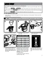
Page 7: ...ee container beneath the brew head COFFEE BREWING INSTRUCTIONS 5 Slide the filled brew basket into the brew rails on the brew head 3 Place a clean filter into the brew basket 4 Fill the filter with the proper amount of ground coffee 6 Start the brew cycle by holding your finger on the desired brew icon As soon as you hear the click of the brew valve the brew cycle has started and you can lift your...

Page 8: ...chscreen Control Module The touch screen turns on whenever power is provided to the brewer and the rear toggle switch is on The symbol buttons on the screen control operation and programming Pressing the on screen symbols and buttons with your finger tip activates the various functions The default screen as well as additional control buttons are shown below ENTER CURTIS LOGO To enter programming t...

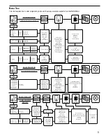
Page 9: ...lution Dual Sweet Standard Purple Standard Gray Standard Amber Tropical Purple Tropical Gray 76 308 Purple 76 308 Gray Temperature Quality Timer Energy Savings Sounds Diagnostics Display Settings Preventative Maintenance Brew Counter Passwords Master Reset Regional Settings Full Only Full Half By Volume Time Dilution by Volume Time Dilution Delay Stir Fast Brew Pulses Drip Out Sweetener Combo Comb...

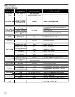
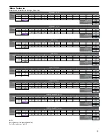
Page 10: ...10 Menu Features ...

Page 11: ...11 NOTE Recipe Defaults are for Seraphim Models Only Custom Recipe feature is enabled Menu Features Default Recipe Brew Button Settings Paper Cup ...

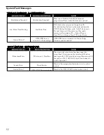
Page 12: ...ther been open for more than 10 minutes on the initial tank fill or has been open for 120 Seconds on Large Brewers and 30 Seconds on CGC ALP D60 Airpot Tea brewers in normal operation If the Inlet valve remains on longer than XX Seconds during the brew cycle only and repeats TWICE during that brew cycle It shall clear upon the next brew and if the same low flow exists again it will re appear XX Al...

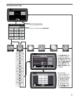
Page 13: ...wo selections Programming Password or Brew Password To set up or change the Brew Password press the Enabled button then the Edit button The BREW PASSWORD screen will appear When resetting a password press Clr then select a new password numbers only If enabling the BREW PASSWORD select a password code Press the icon to set the new password Press the home icon to return to the MAIN MENU and exit Bre...

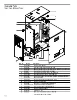
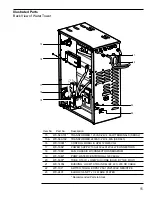
Page 14: ...RACKET SIDE PLATE FRONT FACE SERAPHIM LOGO FRONT FACE W LED LEG 3 8 16 STUD SCREW BUMPER CURRENT SENSOR ASSEMBLY G4 LEG GLIDE 3 8 16 STUD SCREW COVER SIDE ACCESS O RING I D NUT 5 8 18 JAM UNF NICKEL PLATED Recommended Parts to Stock 1 2 3 4 4A 5 6 7 8 8A 9 10 11 12 13 14 WC 61643 WC 2948 WC 8559 WC 847 WC 883 WC 10008 WC 1065 WC 61536 WC 73133 WC 73133K WC 3503 WC 14045 101 WC 3518 WC 61521 WC 432...

Page 15: ...PHIM PUMP WATER CENTRIFUGAL 120V 60Hz TUBE 3 16 ID x 3 32W SILICONE SOLD BY THE FOOT BUSHING LOCKIT STRAIN RELIEF 220 290 OD CABLE SWITCH TOGGLE DPST 25A 125 250VAC RESISTIVE ELBOW 3 8 NPT x 1 4 FLARE PLATED Recommended Parts to Stock 15 15A 16 17 18 19 20 21 22 23 WC 589 101 WC 589 102 WC 10001 WC 1064 WC 1066 WC 1040 WC 5307 WC 14054 WC 103 WC 2401 Item Part Description Illustrated Parts Back Vi...

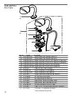
Page 16: ...GRIP NYLON 750 875 KIT WEIR BOX BUSHING KIT SPRAYHEAD FITTING TLP SPRAYHEAD PURPLE ADVANCE FLOW SPRAYHEAD GRAY ADVANCED FLOW FITTING STRAIGHT PLASTIC 12MM TUBE 1 2 ID x 1 8W SILICONE SOLD BY THE FOOT COUPLER 3 16 BARBED STRAIGHT Recommended Parts to Stock 24 24A 25 25A 25B 25C 26 27 27A 28 29 30 31 31A 32 33 34 WC 66099 BLK WC 66099 WHT SERA BH BLK120 SERA BH WHT120 SERA BH BLK200 SERA BH WHT200 W...

Page 17: ...ING TANK INLET KIT FITTING TANK OVERFLOW KIT ELEMENT HEATING 2 5KW 220V NUTS WSHRS KIT HEATING ELEMENT2 0KW 220V SERA33 SENSOR TEMPERATURE TANK GUARD SHOCK HEATING ELEMENT THERMOSTAT HI LIMIT HEATER DPST 277V 40A GUARD SHOCK RESET THERMOSTAT 35 36 37 38 39 39A 40 41 42 43 43A 44 44A 45 46 47 48 WC 53162 WC 37008 WC 43067 WC 5527K WC 62107 WC 62107 33 WC 2221 WC 2628 WC 5310 WC 37365 WC 37266 WC 93...

Page 18: ...REW KIT HOLDER BREW BASKET SERA DRIP TRAY ASSY COMPLETE KIT NOISE FILTER 250V 30A SERA30 33 TRANSFORMER 230 115V 130VA SERA30 TRANSFORMER 208 120V 100VA SERA33 BREAKER CIRCUIT 2 POLE 5A 250V SERA33 NOT SHOWN 49 50 50A 51 51A 52 53 54 55 56 57 58 59 60 61 WC 37580 WC 66095 BLK WC 66095 WHT SERA UH BLK SERA UH WHT WC 65034 WC 65035 CGC4FILTER WC 3411 WC 73141K WC 65041 WC 596K WC 592 WC 598 WC 1512 ...

Page 19: ...sed 9 Not Used 10 Not Used 11 Brew Pump 12 Brew Pump 13 Not Used 14 Not Used 15 Not Used 16 Not Used 17 Not Used 18 Not Used 19 Current Sensor 20 Current Sensor UPM Pin Assignments r o t c e n n o C n i P 0 2 1 TX Transmit 2 RX Receive 3 Not Used 4 Vdd 5Vdc 5 Vss Logic_Common r o t c e n n o C n i P 5 1 12 Vac Input Back Light 2 Vdd 5Vdc 3 Vss Logic_Common 4 Not Used 5 12 Vac Input Back Light 6 Da...

Page 20: ...Clean the brew basket rails with a brush Rinse with a water soaked cloth Dry the area with a clean cloth 5 Attach the spray head and insert the brew basket into the brew rails 6 Restore the electrical power to the brewer Liquid Level Probe Cleaning intervals for the probe are to be determined by the user or the service tech based on water conditions The use of water filters or the type of water fi...

Page 21: ...nsert the brush into the side opening and spin it a few times Run the brush completely through the side opening 4 Rinse the brew basket with clear water Observe the flow of water from the dispens ing spout to make sure you have a good flow Replace the cap on top of the spout tube Push down on the cap until it snaps into place Caring for the LCD Display To remove light smears or grime wipe the surf...

Page 22: ...22 Rough In Drawing SERA2 ...

Page 23: ......

Page 24: ...g circumstances Improper operation of equipment The equipment must be used for its designed and intended purpose and function Improper installation of equipment This equipment must be installed by a professional technician and must comply with all local electrical mechanical and plumbing codes Improper voltage Equipment must be installed at the voltage stated on the serial plate supplied with this...

Reviews: