I.L. 29C171
Effective March 1998.
Cutler-Hammer
Installation Instructions for Undervoltage Release
Mechanism (Handle Reset) with LED for E
2
L and E
2
LM
Mining Circuit Breakers
CONTACT WITH ENERGIZED EQUIPMENT CAN
RESULT IN DEATH, SEVERE PERSONAL INJURY,
OR SUBSTANTIAL PROPERTY DAMAGE. DO NOT
ATTEMPT TO INSTALL OR PERFORM MAINTE-
NANCE ON EQUIPMENT WHILE IT IS ENERGIZED.
ALWAYS VERIFY THAT NO VOLTAGE IS PRESENT
BEFORE PROCEEDING WITH THE TASK, AND
ALWAYS FOLLOW GENERALLY ACCEPTED SAFE-
TY PROCEDURES.
CUTLER-HAMMER IS NOT LIABLE FOR THE MISAP-
PLICATION OR MISINSTALLATION OF ITS PROD-
UCTS.
The user is cautioned to observe all recommendations,
warnings, and cautions relating to the safety of person-
nel and equipment as well as all general and local
health and safety laws, codes, and procedures.
!
WARNING
The recommendations and information contained herein
are based on Cutler-Hammer experience and judge-
ment, but should not be considered to be all-inclusive or
covering every application or circumstance which may
arise. If any questions arise, contact Cutler-Hammer for
further information or instruction.
1.0 INTRODUCTION
General Information
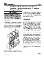
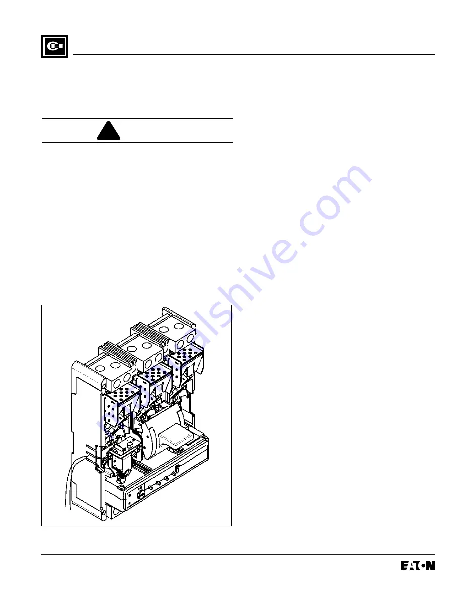
The undervoltage release mechanism (UVR) (Figure 1-
1) monitors a voltage (typically a line voltage and trips
the circuit breaker when the voltage falls to between 70
and 35 percent of the solenoid coil rating. The UVR
consists of a continuous rated solenoid with a plunger
and reset lever assembled to a plug-in module. The
plug-in module is mounted in slots in the top of the trip
unit and occupies the accessory cavity in the circuit
breaker frame. The reset lever resets the UVR when
normal voltage is restored and the circuit breaker handle
is moved to the resets (extreme OFF) position. With no
voltage applied to the UVR, the circuit breaker contacts
will not touch when a closing operation is attempted.
The UVR is available for 120 VAC. Table 1.1 lists appli-
cations and electrical ratings data for the UVR.
For this publication, the term circuit breaker shall also
include molded case switch and motor circuit protector.
Depending on the model ordered, connections for the
UVR are in one of four forms. The standard wiring con-
figuration is pigtail leads exiting the rear of the base
directly behind the UVR. Optional configurations
include a terminal block mounted on the same side of
the base as the accessory, leads exiting the side of the
base where the accessory is mounted, and leads exiting
the rear of the base on the side opposite the accessory.
The 18-inch long pigtail leads are color coded for identi-
fication; identification labels are provided for pigtail
leads and terminal block points.
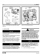
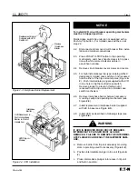
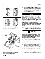
This instruction leaflet (IL) gives detailed procedures for
installing the UVR.
Figure 1-1 Undervoltage Release Mechanism (Handle
Reset) with LED installed in L-Frame Mining Circuit Breaker

