Installation Instructions
Modernist Pro Range
DOP48M96DL*/DOP36M94DL*
Install_NY9900M_PRORANGE_DOP48M96DLM_DA_DG68-00936A-00_EN+MES+CFR.indb 1
2017-05-12 7:36:36
Page 1: ...Installation Instructions Modernist Pro Range DOP48M96DL DOP36M94DL Install_NY9900M_PRORANGE_DOP48M96DLM_DA_DG68 00936A 00_EN MES CFR indb 1 2017 05 12 7 36 36...
Page 2: ...ns 21 What s in the box 21 Installation requirements 24 Pre installation checklist 24 General requirements 24 Location requirements 28 Gas requirements 31 Special gas requirements gas models sold in M...
Page 3: ...his manual for guidance It provides useful suggestions and remedies prior to calling for service Valuable customer input helps us to continuously improve our products and services so please feel free...
Page 4: ...O NOT light any appliances DO NOT touch any electrical switches DO NOT use any phone in your building Immediately call your gas supplier from a neighbor s phone and follow the supplier s instructions...
Page 5: ...this manual thoroughly before starting the installation Leave this manual with the user Write the appliance s model serial numbers in this manual for service maintenance reference User Keep this manua...
Page 6: ...ty of the installer Product failure due to improper installation is not covered under the Warranty Important note to the consumer Keep these instructions with your user manual for future reference As...
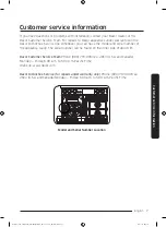
Page 7: ...number of the appliance ready The serial number can be found on the inner side of door trim Dacor Customer Service Team Phone 800 793 0093 ex 2813 U S A and Canada Monday Friday 6 00 a m to 5 00 p m...
Page 8: ...on Instructions Check for proper installation by carefully tipping the range forward The anti tip device should engage and prevent the range from tipping over If the range is pulled out away from the...
Page 9: ...nual in a handy place so you can refer to it as needed Symbols used in this manual WARNING Hazards or unsafe practices that may result in severe personal injury or death CAUTION Hazards or unsafe prac...
Page 10: ...reduce the risk of fire electric shock personal injury or death observe these precautions Do not touch any surface component or mechanism of the product during or immediately after cooking Learn wher...
Page 11: ...ked to an internal temperature of 160 F 71 C Poultry should always be cooked to an internal temperature of 180 F 82 C An air curtain or other overhead range hood which operates by blowing a downward a...
Page 12: ...touch a heating element Do not use a towel or other bulky cloth item as a pot holder Do not douse a grease fire with water Instead turn off the heat source and smother the fire with a tight fitting li...
Page 13: ...ne from the building Immediately call your gas supplier from a neighbor s phone Follow the gas supplier s instructions If you cannot reach your gas supplier call the fire department Checking for gas l...
Page 14: ...ounding reduces the risk of electric shock by providing a safe path for the current This range s power cord has a grounding plug which must be firmly plugged into an outlet that is properly installed...
Page 15: ...Cautiously handle the heavy grates Make sure no parts came loose during shipping Make sure the product is correctly installed adjusted by a qualified service technician or installer for the type of g...
Page 16: ...ng The range must be installed within easy reach of a grounded 3 prong outlet Do not hang paper blinds on a window near the range do not hand long curtains that could be blown over onto the range For...
Page 17: ...n Before removing or changing cookware turn off the burners Remove food and cookware immediately after cooking Make sure all cooktop burners are off and all surfaces have completely cooled before remo...
Page 18: ...he temperature can stabilize In the event of scalding follow these first aid instructions 1 Immerse the scaled area in cool or lukewarm water for at least 10 minutes 2 Do not apply any creams oils or...
Page 19: ...ooking When using cooking or roasting bags in the oven follow the manufacturer s directions Do not use harsh abrasive cleaners or sharp metal scrapers to clean the oven door glass They can scratch the...
Page 20: ...and food soils from the oven Excessive amounts of grease may ignite leading to smoke damage to your home When opening the door after a self cleaning cycle stand away from the oven If the self cleaning...
Page 21: ...Temp Probe 2 Glide racks 2 WOK ring 1 Anti tip bracket 1 Wire rack 1 Small rack 1 Steam tray 2 Half steam tray 2 NOTE The range is supplied with two different types of burner caps brass and porcelain...
Page 22: ...caps 5 Wire rack 1 Convection filter 2 Temp Probe 1 Glide racks 2 Griddle 1 WOK ring 1 Anti tip bracket 1 The range is supplied with two different types of burner caps brass and porcelain to suit the...
Page 23: ...elbow optional Lag bolt or in OD sleeve anchor Flare union adapter in NPT x in ID Tools needed Flat blade screwdriver Phillips screwdriver Open end or adjustable wrench Pipe wrench 2 Nut driver Pencil...
Page 24: ...ation of the electrical outlet and gas piping may be adjusted to meet the following dimensions and clearances The range may be installed flush to the rear wall Dacor strongly recommends installing a n...
Page 25: ...etween the cooking surface and the ventilation hood surface must never be less than 24 inches Exception Installation of a listed microwave oven or cooking appliance over the range shall conform to the...
Page 26: ...8M96DL 47 7 8 121 6 cm The optional backguard is available in two heights 3 and 9 inches high 24 61 0 cm Cabinet face 29 7 8 75 9 cm Countertop height 36 3 16 91 9 cm min 37 1 2 95 3 cm max Cabinet fa...
Page 27: ...cabinets CUTOUT DIMENSIONS Range Model A B C DOP36M94DL 42 106 7 cm 36 91 4 cm 36 91 4 cm 36 1 8 91 7 cm 33 1 2 84 8 cm DOP48M96DL 54 137 2 cm 48 121 9 cm 48 121 9 cm 48 1 8 122 2 cm 9 22 9 cm Recomme...
Page 28: ...panel see product dimensions 3 Consult local code for exact location requirements 4 Vertical from grate level to combustible surface 5 This specification does not apply for cabinets more than a horizo...
Page 29: ...6 5 8 22 5 cm 8 7 8 28 4 cm 11 3 16 1 Measurement with appliance legs adjusted to lowest height 2 The hole size for the electrical wiring may be increased to 1 1 8 2 9 cm by removing the conduit brack...
Page 30: ...lation must allow for the following Access to the gas shut off valve when the unit is installed Access to the remote circuit breaker panel fuse box when the range is in place The gas supply piping and...
Page 31: ...e gas service provided natural gas When checking for proper operation of the regulator the inlet pressure must be at least 1 in 2 5 cm greater than the operating manifold pressure as given GAS SUPPLY...
Page 32: ...ll used connectors which can leak gas and cause personal injury Use only new flexible connectors Special gas requirements gas models sold in Massachusetts COMMONWEALTH OF MASSACHUSETTS REQUIREMENTS WA...
Page 33: ...ange power plug If it does not fit the outlet have a proper outlet installed by a qualified electrician All wiring and grounding must comply with local codes or in the absence of local codes with the...
Page 34: ...gas and electrical connections Install it according the installation instructions included with the backguard kit Approved backguard kits Model Description APB36D3 3 inch high backguard for range mod...
Page 35: ...racket to the floor Use both the anchors and four 4 of the screws when attaching the bracket to a concrete sub floor Do not use the provided anchors when attaching to a wood sub floor 1 Determine the...
Page 36: ...o the anchors Be sure the screw threads fully engage the anchor body Tighten the screws into place Attaching the bracket to a wood floor If there is ceramic asphalt or other hard floor covering over t...
Page 37: ...ver 1 4 and up to 1 2 thick 8 x 1 1 4 Wood sub floor floor covering over 1 2 and up to 1 3 16 thick 12 x 1 3 4 Concrete under floor covering over 1 2 thick Must be purchased separately Wood sub floor...
Page 38: ...sed on the diagram above Push the bracket up against the wall in the mounting location Using a pencil make a dot next to the notches on both sides of the bracket Determine if the base plate is as high...
Page 39: ...cket center line Range center line Range front panel Bracket center line Top View Location of Wall Mounted Anti Tip Bracket ANTI TIP BRACKET PLACEMENT Dimension DOP36M94DL DOP48M96DL C 14 1 8 35 9 cm...
Page 40: ...to reduce weight Catch Retaining arm 1 Open the door to its fully opened position 2 Use a pair of needle nose pliers or a flat blade screwdriver to rotate the catch over the retaining arm on each hing...
Page 41: ...We recommend you have the electrical wiring and hookup of your range connected by a qualified electrician After installation have the electrician show you where your main range disconnect is located C...
Page 42: ...terminals on wire and a strain relief device A range cord rated at 40 amps with 125 250 minimum volt range is required A 50 amp range cord is not recommended but if used it should be marked for use w...
Page 43: ...crewdriver The terminal block will then be accessible Specified power supply cord kit rating Range rating watts Specified rating of power supply cord kit amperes Diameter inches of range connection op...
Page 44: ...cord must be connected to the neutral terminal located in the center of the terminal block The power leads must be connected to the lower left and the lower right terminals of the terminal block Groun...
Page 45: ...lack White Red 1 Remove the 3 lower terminal screws from the terminal block Remove the ground screw and ground plate and retain them 2 Cut and discard the ground strap Do not discard any screws 3 Inse...
Page 46: ...in Figure 1 2 Install the conduit cord as shown in Figure 2 Conduit connection plate Strain relief Ring Body Figure 2 1 3 1 3 3 wire 4 wire Knockout surface Figure 1 For conduit installations insert...
Page 47: ...the 3 lower terminal screws from the terminal block 2 Insert the center bare wire white neutral tip through the bottom center terminal block opening On certain models the wire will need to be inserted...
Page 48: ...inal block Remove the ground screw and ground plate and retain them 2 Cut and discard the ground strap Do not discard any screws 3 Insert the ground bare wire tip between the range frame and the groun...
Page 49: ...ply piping during any pressure testing exceeding psi 3 5 kPa The range must be isolated from the gas supply piping by closing the shut off valve during any pressure testing at or below 1 2 psi 3 5 kPa...
Page 50: ...he access holes in the chassis and up to the regulator Move the wires around inside the access holes to prevent them from catching on the gas line as you push it up 4 Connect the gas line to the regul...
Page 51: ...ate the anti tip foot on the back of the range and lower turn it until it is 1 16 2 mm off the floor Anti tip bracket Anti tip foot 4 Carefully slide the range into position into the cutout The anti t...
Page 52: ...ings resting the bottom of the hinge arms on the hinge receptacles Continue to hold the door at a 15 angle with one hand while pushing in on each of the bottom corners of the door Push until the notch...
Page 53: ...r up and down Lifting hinge latch up To adjust door up and down 1 Remove door and remove 2 screws on door hinge latch 2 Turn the bolt under each door hinge latch 3 After adjusting the door hinge latch...
Page 54: ...D shaped opening on the back of the knob with the end of the valve shaft Carefully push the knob on until it stops There are two 2 different types of knobs supplied with the range One is for griddle...
Page 55: ...g you to knock over hot cookware Do not risk electric shock by removing the top or touching the electrode of any burner while another burner is on 1 Place the burner heads on the burner bases as shown...
Page 56: ...rode aligns with the electrode 2 Install the burner head so the electrode passes through its opening in the head Ensure the burner head lies flat on the stove top 3 Match the burner caps to the burner...
Page 57: ...into place Twist the head back and forth slightly to ensure it is properly seated 3 Put the burner caps brass or porcelain atop the burner heads The ridge around the bottom edge of the cap fits around...
Page 58: ...e tabs on the bottom of the ring to the slots on the burner head Twist each ring back and forth slightly to make sure it is properly seated Ridge on bottom of burner cap 3 Put the burner caps on top o...
Page 59: ...the grates correctly See the graphic below To correctly position the grates 1 Find the notch on the back of the right hand grate and orient the grate properly above the right hand burners 2 Gently low...
Page 60: ...open the door to make sure the air inside oven has begun to heat 8 The display should show BAKE and the preheating temperature 9 Touch OFF to stop oven heating process 10 Test one of the burners by p...
Page 61: ...ctly 3 Repeat the above bake test or burner ignition test 4 If the appliance still does not work contact Dacor Distinctive Service at 800 793 0093 ex 2822 Do not attempt to repair the appliance yourse...
Page 62: ...English 62 Installation instructions Installation instructions Install_NY9900M_PRORANGE_DOP48M96DLM_DA_DG68 00936A 00_EN MES CFR indb 62 2017 05 12 7 36 55 This page left blank intentionally...
Page 63: ...panel or fuse box 3 Pull the range out from the wall Reinstalling the Range After Service 1 Push the range into operating position making sure the anti tip bracket is engaged see page 51 2 Turn on pow...
Page 64: ...cording to these instructions and in accordance with all applicable electrical codes Has the electrical access cover been replaced See pages 33 and 41 to 48 Has the gas supply inlet pressure been meas...
Page 65: ...MEMO Install_NY9900M_PRORANGE_DOP48M96DLM_DA_DG68 00936A 00_EN MES CFR indb 65 2017 05 12 7 36 55...
Page 66: ...MEMO Install_NY9900M_PRORANGE_DOP48M96DLM_DA_DG68 00936A 00_EN MES CFR indb 66 2017 05 12 7 36 55...
Page 67: ...rst exposed to Dacor products Please check one only A T V Cooking Show F Builder B Magazine G Architect Designer C Appliance Dealer Showroom H Another Dacor Owner D Kitchen Dealer Showroom I Model Hom...
Page 68: ...r 14425 Clark Avenue City of Industry CA 91745 Phone 800 793 0093 Fax 626 403 3130 www dacor com DG68 00936A 00 Install_NY9900M_PRORANGE_DOP48M96DLM_DA_DG68 00936A 00_EN MES CFR indb 68 2017 05 12 7 3...