1
Please read all instructions thoroughly before installing the over the range microwave oven/hood system. Two
people are recommended to install this product.
If a new electrical outlet is required, its installation should be completed by a qualified electrician before the over
the range microwave oven/hood system is installed. See 3 ELECTRICAL GROUNDING INSTRUCTIONS on page 2.
1 MOUNTING SPACE
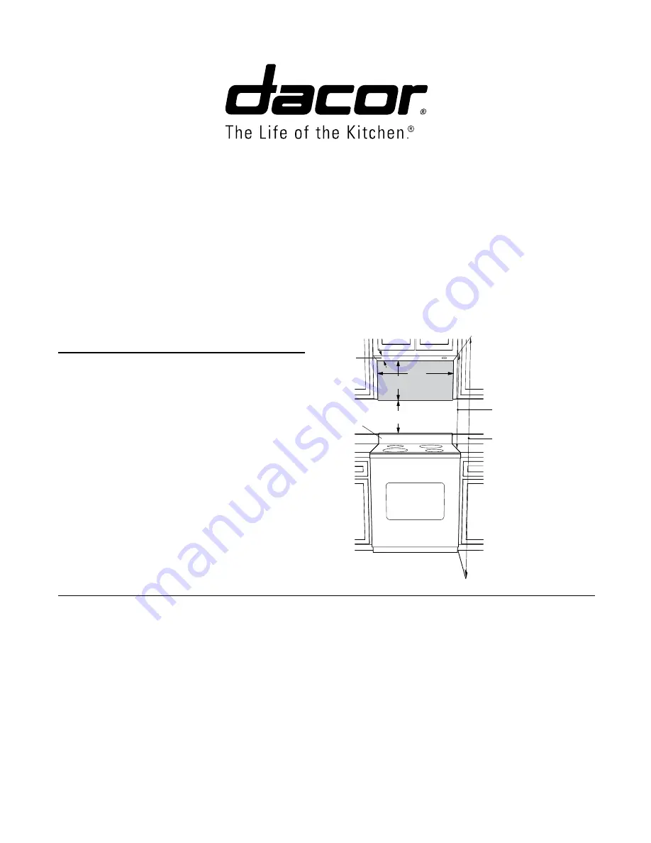
This microwave oven/hood requires a mounting space on
a wall as shown in Figure 1. It is designed to be used with
standard 12-inch wall cabinets.
Consult the installation instructions for the range or cooktop
being installed for additional and/or superseding minimum
distance requirements.
2 WALL CONSTRUCTION
This microwave oven/hood should be mounted against and supported by a flat vertical wall. The wall must be flat for proper
installation. If the wall is not flat, use spacers to fill in the gaps. Wall construction should be a minimum of 2” x 4” wood studding
and 3/8” or more thick dry wall or plaster/lath. The mounting surfaces must be capable of supporting a weight of 110 pounds—the
oven and contents—AND the weight of all items which would normally be stored in the top cabinet above the unit.
The unit should be attached to a minimum of one 2” x 4” wall stud.
To find the location of the studs, one of the following methods may be used:
A. Use a stud finder, a magnetic device which locates the nails in the stud.
B. Use a hammer to tap lightly across the mounting surface to find a solid sound. This will indicate stud location.
The center of the stud can be located by probing the wall with a small nail to find the edges of the stud and then placing a mark
halfway between the edges. The center of any adjacent studs will normally be 16” or 24” to either side of this mark.
Figure 1
At least 2"
15.5"
30"
12"
Backsplash
66" or more
from floor
30" or more from
cooking surface
PCOR30 OVER THE RANGE
MICROWAVE OVEN / HOOD SYSTEM
INSTALLATION INSTRUCTIONS
Part No. 107002 Rev. C
TINSEB319MRR1


