background image

PS-MMA0415-E1A


MAINTENANCE MANUAL 


Diesel Engine 

D1146 

D1146TI 

DE08TIS 


65.99897-8056 

Feb. 2001 

Summary of Contents for D1146

Page 1: ...PS MMA0415 E1A MAINTENANCE MANUAL Diesel Engine D1146 D1146TI DE08TIS 65 99897 8056 Feb 2001...

Page 2: ...ptimum condition and retain maximum performance for a long time CORRECT OPERATION and PROPER MAINTENANCE are essential In this manual the following symbols are used to indicate the type of service ope...

Page 3: ...special waste If you have any question or recommendation in connection with this manual please do not hesitate to contact our head office dealers or authorized service shops near by your location for...

Page 4: ...y 8 2 MAJOR MAINTENANCE 2 1 Preventive Maintenance 13 2 2 Diagnosis and Remedy 22 2 3 Engine Inspection 32 3 MAINTENANCE 3 1 Engine Disassembly 33 3 2 Inspection and Measurement on Major Parts 48 3 3...

Page 5: ...lock washer and self lock nuts should be discarded and new ones should be prepared for installation as normal function of the parts can not be maintained if these parts are reused 7 To facilitate prop...

Page 6: ...perfect combustion by the more smooth mixing of air and fuel which was injected through multi nozzles in the combustion chamber This engine by means of Toroidal Combustion Mode has the specific charac...

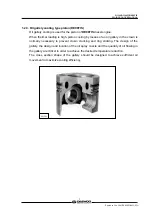
Page 7: ...oling by means of an oil gallery in the crown is normally necessary to prevent crown cracking and ring sticking The design of the gallery the design and location of the oil spray nozzle and the quanti...

Page 8: ...pe Zexel in line AD type Zexel in line P type Governor type Mechanical governor type RLD Mechanical governor type RLD J Injection nozzle type Multi hole type 5 hole Multi hole type 7 hole Fuel injecti...

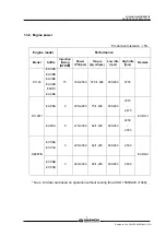
Page 9: ...Low idle rpm High idle rpm Remark D1146 EACBA EACBB EACBE EACBH EACBI EACBK 15 182 2 500 57 5 1 600 600 650 2750 EAPBA 9 205 2 200 75 1 400 600 650 2370 2 470 D1146TI EAPCA 9 215 2 300 82 1 400 600 65...

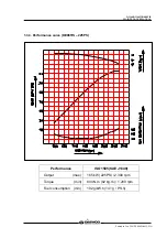
Page 10: ...NCE MANUAL 6 Printed in Jan 2001 PS MMA0415 E1A 1 3 3 Performance curve DE08TIS 225PS Performance ISO 1585 SAE J1349 Output max 165 kW 225PS 2 300 rpm Torque min 804 N m 82 kg m 1 200 rpm Fuel consump...

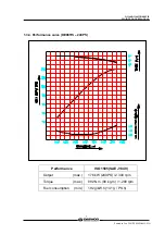
Page 11: ...NCE MANUAL 7 Printed in Jan 2001 PS MMA0415 E1A 1 3 4 Performance curve DE08TIS 240PS Performance ISO 1585 SAE J1349 Output max 176 kW 240PS 2 300 rpm Torque max 882 N m 90 kg m 1 200 rpm Fuel consump...

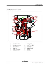
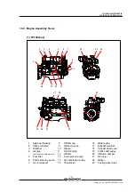
Page 12: ...Breather 7 Cylinder head cover 8 Exhaust valve spring 9 Cylinder head 10 Intake valve spring 11 Cylinder block 12 Push rod 13 Flywheel housing 14 Ring gear 15 Tappet 16 Cam shaft 17 Fly wheel 18 Oil...

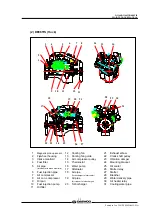
Page 13: ...injection pipe 9 Turbo charger 2 Fuel filter 10 Fuel injection pump 3 Fuel injection nozzle 11 Timing gear case 4 Intake manifold 12 Oil filler cap 5 Air heater 13 Connecting rod 6 Rocker arm 14 Oil s...

Page 14: ...17 Exhaust manifold 3 Breather 10 Oil pan 18 Cylinder head cover 4 Air pipe 11 Oil drain plug 19 Crank shaft pulley Air cleaner to intake manifold 12 Oil filter 20 Vibration damper 5 Fuel filter 13 F...

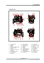
Page 15: ...stat 24 Mounting bracket 5 Air pipe 16 Water pump 25 Oil cooler Intercooler to intake manifold 17 Alternator 26 Starter relay 6 Fuel injection pipe 18 Air pipe 27 Starter 7 Air compressor Turbocharger...

Page 16: ...fold 13 Oil pan 23 Mounting bracket 4 Fuel injection pipe 14 Oil filter 24 Oil cooler 5 Air pipe 15 Fuel injection pump 25 Turbocharger Turbocharger to intercooler 16 Vibration damper 26 Starter 6 Fue...

Page 17: ...ality of engine For the improper control might give the fatal damage to the cooling water pump and cylinder liners detail care is needed zSince D1146 D1146TI and DE08TIS diesel engine of D1146 series...

Page 18: ...ust prevention and the proper range is that the meeting numerical value of brown vertical and pink color horizontal locates in the range of 0 3 to 0 8 at the color list of label on the test paper stor...

Page 19: ...First oil change After 1 000km 50hr operation D1146 TI every 10 000km Short distance operation vehicle city bus dump truck DE08TIS every 20 000km D1146 TI every 15 000km Long distance operation vehicl...

Page 20: ...e it z By the definite interval the elements must be cleaned and replaced 2 1 7 Intercooler The intercooler is air to air type and has a large cooling fan capacity The intercooler life and performance...

Page 21: ...djusting screw respectively and then tighten with the lock nut z As for the valve clearance adjust it when in cold as follows Model Intake Valve Exhaust Valve D1146 D1146TI DE08TIS 0 3 mm 0 3 mm 1 Rot...

Page 22: ...4 Thereafter adjust the valve clearances corresponding to of lower figure 5 After reinsuring the valve clearances retighten if necessary z No 1 cylinder is located at the side where flywheel was insta...

Page 23: ...10 Condition Water temperature 20 C Engine rotation 200rpm 10 rotations 2 1 10 Injection nozzle z Install a nozzle on the nozzle tester z If the inspected injection pressure is less than the specifie...

Page 24: ...n pump has the function of air removal continuously during the operation through a relief valve In case that the suction room lacks fuel at all for instance in case of new installation of injection pu...

Page 25: ...and must clean with non acid solvent solution If necessary use plastic scraper If impeller is severely polluted dip the impeller into solution and may be better to clean it with stiff brush Then one t...

Page 26: ...in Jan 2001 PS MMA0415 E1A 2 2 Diagnosis and Remedy z The following description summarizes the probable cause of and remedy for generall failure by item z Immediate countermeasures should be taken bef...

Page 27: ...D1146 D1146TI DE08TIS MAINTENANCE MANUAL 23 Printed in Jan 2001 PS MMA0415 E1A Operating state 1 Overload 2 Radiator core clogged 3 Continuous over run Inspect Radiator Check fresh Radiator tank cap...

Page 28: ...D1146 D1146TI DE08TIS MAINTENANCE MANUAL 24 Printed in Jan 2001 PS MMA0415 E1A...

Page 29: ...D1146 D1146TI DE08TIS MAINTENANCE MANUAL 25 Printed in Jan 2001 PS MMA0415 E1A...

Page 30: ...AL 26 Printed in Jan 2001 PS MMA0415 E1A Causes according to operating conditions 1 Overload 2 Freqent use of low geae position at high speed 3 Freqent use of high geae position at low speed 4 Clutch...

Page 31: ...D1146 D1146TI DE08TIS MAINTENANCE MANUAL 27 Printed in Jan 2001 PS MMA0415 E1A Cause according to use conditions 1 Excessive oil infusing 2 continuous operation in low speed or extremely cold state...

Page 32: ...D1146 D1146TI DE08TIS MAINTENANCE MANUAL 28 Printed in Jan 2001 PS MMA0415 E1A...

Page 33: ...Adjust or replace z Supply pump s function lowered Repair or replace z Fuel pipe system clogged Repair z Air suction amount insufficient Clean or replace air cleaner z Turbocharger poor Repair or rep...

Page 34: ...z Stuck bearing Replace grind crankshaft z Oil supply insufficiency as clogging at oil passage progresses Clean oil passage 3 Piston piston pin Piston ring z Piston clearance increase as the wear of...

Page 35: ...z Piston ring opening s disposition improper Correct position z Piston skirt part damaged or abnormal wear Replace piston z Oil ring s oil return hole clogged Replace piston ring z Oil ring s contact...

Page 36: ...cleaner element Drain the water in separator Clean the fuel strainer of fuel feed pump Check the fuel line leakage Check fuel Injection timing When necessary Replace the fuel filter cartridge Fuel Sys...

Page 37: ...f disassembly the parts should be laid in order 3 1 2 Oil level gauge z Pull out the oil level gauge 3 1 3 Cooling water z Remove the radiator cap Open the drain valve at the radiator lower part to dr...

Page 38: ...d vessel 3 1 5 Cooling fan zRemove the flange fixing bolts then take off the flange and cooling fan 3 1 6 Belt z Loosen the tension adjusting bolts of the alternator and the idle pulley and take off t...

Page 39: ...f filter and tear down fuel supply and discharge rubber hose z Remove fuel filter fixing bolts and disassemble the fuel filter If the fuel filter is of cartridge type disassemble the cartridge element...

Page 40: ...and the rubber hose clamps of connected pipes and disassemble it z Remove the oil cooler fixing bolts and take off the oil cooler 3 1 14 Oil filter z Remove the oil filter fixing bolts and take off th...

Page 41: ...r fixing bolts and take off the air compressor 3 1 17 Idle pulley z Unscrew the idle pulley fixing bolts and take off the idle pulley 3 1 18 Water pump z Unclamp the rubber hose connected to the oil c...

Page 42: ...ake out the seal ring from the nozzle hole of the cylinder head and discard it 3 1 21 Turbo charger D1146TI DE08TIS z Remove the oil supply pipe and oil return pipe between the turbo charger and the c...

Page 43: ...he cooling water pipe gasket and finish the surface with a scraper CAUTION Be sure that piece of the gasket do not come into the cooling water passage 3 1 25 Rocker arm z Remove the rocker arm bracket...

Page 44: ...ve the total bolts simultaneously by the step of 1 and 2 z Lay the removed bolts orderly not to damage the threads at all and store CAUTION Prevent a collision between the bolt thread each other z Tak...

Page 45: ...z Unscrew the oil pan fixing bolts and remove the oil pan z Remove the oil pan gasket and discard it 3 1 28 Vibration damper z Unscrew the vibration damper fixing bolts in reverse sequence of install...

Page 46: ...r of assembling but do same as the cylinder head bolt removal z Disassemble the upper lower of connecting rod caps by tapping lightly with urethane hammer and remove the bearing z By pushing the conne...

Page 47: ...ston as tapping it with a round wooden bar 3 Remove the piston ring with a plier 4 Clean the piston thoroughly 3 1 32 Cylinder liner z Disassemble the cylinder liner with a special tool or hand but be...

Page 48: ...ge z Unscrew the injection pump fixing bolts and remove the injection pump by lifting it up z Remove the bracket fixing bolts of injection pump and disassemble by pulling the injection pump backward 3...

Page 49: ...and remove the drive gear assembly 3 1 39 Timing gear case z Remove the timing gear case assembling bolts z By tapping lightly with a urethane hammer the right and left back of timing gear case s con...

Page 50: ...Disassemble the metal bearings in turn and store them NOTES Do not mingle with the metal bearings and bearing caps randomly To prevent mixing temporarily assemble the metal bearings to the correspond...

Page 51: ...D1146 D1146TI DE08TIS MAINTENANCE MANUAL 47 Printed in Jan 2001 PS MMA0415 E1A 3 1 43 Oil spray nozzle D1146TI DE08TIS only z Remove the valve screws of oil spray nozzle and disassemble it...

Page 52: ...oil discharge ports and apply the air pressure of about 4kg cm2 to intake port and soak it in water for about 1 minute to check if there is any leakage Water temperature 70 C 3 2 2 Cylinder head 1 Cy...

Page 53: ...at 6 directions with horizontal ruler and clearance gauge z If the measured value is beyond the limit value correct it by means of the fine grinding paper or grinding machine z If it is beyond the ma...

Page 54: ...em 8 935 8 955 mm 8 91 mm z Valve seat contacting faces Check the valve seat contact surface for any crack and wear and if necessary correct with grinding paper and if excessive replace it z Valve hea...

Page 55: ...Valve seat z Contacting face amount As for the valve seat s wear measure the width of the contact surface with intake valve seat and exhaust valve seat If beyond the limit value replace the valve sea...

Page 56: ...bench press z Apply valve lapping compound to the valve head seating face on the valve seat and lap the valve seat by turning it until it is seated in position then wipe out the lapping compound 4 Val...

Page 57: ...the measured value is less than the specified limit the valve spring must be replaced Set Length Spring force Limit Intake valve Valve Spring Tension at 41mm Set Length 70 kg 3 D1146 TI 28 6 kg 6 Inne...

Page 58: ...t tapping it lightly with urethane hammer 3 2 3 Rocker arm assembly 1 Disassembly 1 Disassemble the snap rings that are located at both ends of rocker arm shaft by a plier 2 Disassemble in the order o...

Page 59: ...eck the face of the rocker arm in contact with the valve stem end for scores and step wear If the wear is small correct it with an oil stone or grinding paper of fine grain size Rocker arm with a cons...

Page 60: ...he tappets in contact with the cam for pitting scores or cracks and replace if severely damaged If the amount of cracks or pitting is small correct with an oil stone or grinding paper z Outside diamet...

Page 61: ...play z Push the thrust plate toward the cam gear z With a feeler gauge measure the clearance between the thrust plate and camshaft journal z If the end play is excessive replace the thrust plate Stand...

Page 62: ...mshaft journal diameter Measure the inside diameter of the camshaft bushing on the cylinder block using a cylinder bore indicator and compare the measured value with the camshaft outside diameter to d...

Page 63: ...ith an outside micrometer measure the diameter of the crankshaft journals and pins in the directions as shown and compare the measured values to determine the amount of wear z If the amount of wear is...

Page 64: ...r than the standard size 1 00 Inside diameter is 1 00 mm lesser than the standard size Undersize bearings are available in 4 different sizes as indicated above and the crankshaft can be reused through...

Page 65: ...cylinder block tighten the bearing cap to specified torque then measure the inside diameter Torque 30 kg m Compare the two values obtained through measurement of main bearing inside diameter with the...

Page 66: ...and pins ground and install undersize bearings 3 Oil clearance between crankshaft and bearing Method 2 plastic gauge z Assemble the crankshaft on the cylinder block and put plastic gauge on the journ...

Page 67: ...nder block retighten the bolts to specified torque unscrew out one bolt completely then measure the clearance between the bearing cap and cylinder block using a feeler gauge Standard 0 19 0 22 mm z Co...

Page 68: ...ff or wear paying particular attention to the ring groove 2 Clearance between the piston and cylinder liner z With an outside micrometer measure the piston outside diameter at a point 13mm away from t...

Page 69: ...iston and liner Standard 0 103 0 139 mm 3 Piston rings 1 Visual check Replace the piston rings with new ones if detected worn or broken when the engine is overhauled 2 Piston ring gap z Insert the pis...

Page 70: ...Limit Top ring 2nd ring 0 07 0 102 mm 0 15 mm Oil ring 0 05 0 085 mm 0 15 mm 4 Piston ring tension With a tension tester measure piston ring tension Replace the piston ring if the measured value is be...

Page 71: ...he piston is normal When replacing the piston be sure to replace the piston pin together 5 Connecting rod inspection 1 Distorsion Check the connecting rod for distortion As shown in the figure below i...

Page 72: ...clearance z If the measured values are beyond the limit replace the connecting rod Limit 0 5 mm 3 2 7 Fuel injection nozzle projection DE08TIS z Insert a seal ring on the cylinder head and assemble th...

Page 73: ...Apply only the specified torque for bolts in the specified tightening order and avoid over tightening z Be sure to check that all the engine parts operate smoothly after being reassembled z Check the...

Page 74: ...the pressing operation measure the inside diameter of the cam bush to check if it is not deformed zApply engine oil to the entire face of the tappets and slide them into the tappet holes on the cylind...

Page 75: ...t the crankshaft gear for at least 10 minutes to 120 C then apply sealant Loctite 641 to the inside wall of the heated crankshaft gear evenly before inserting it to the end of crankshaft z Semi tighte...

Page 76: ...bolts then tighten in tightening sequence to specified torque Torque 30 kg m zAfter semi tightening both bolts evenly tighten them diagonally to the specified torque using a torque wrench as follows...

Page 77: ...nce to specified torque Zigzag method Torque 8 kg m CAUTION When the bolts are tightened remove the guide bar z The flywheel housing is assembled after the new oil seal was pressed Coat engine oil ove...

Page 78: ...lot bearing to the flywheel z By means of mandrel press in the wear ring at the backward face z Install a guide bar into a bolt hole on the crank shaft and lift the flywheel to align the dowel pin wit...

Page 79: ...lerance limit is 27 gap 0 1 mm 3 3 10 Water chamber cover z Coat the adhesive over the water chamber cover Particular around bolt holes and after attaching the gasket assemble it to the cylinder block...

Page 80: ...oximately 100 C 212 F for 5 minutes z Align the piston pin hole with the oiled connecting rod small end and press the piston pin by lightly tapping with a rubber hammer to assemble the connecting rod...

Page 81: ...ce upward The surface marked as Y is upper surface z Adjust the angle among individual piston ring gaps to 90 and fit a piston assembling jig onto the piston Use care not to match the ring gaps with t...

Page 82: ...rod cap by aligning it with dowel pin z Wet the fixing bolts with engine oil semi tighten them with hand tighten them to the specified torque using a torque wrench as follows Tightening Order 1 First...

Page 83: ...icularly around dowel pin z Tighten the bolts for assembling to the specified torque However in case of tightening the bolts tighten primarily the bolts of both end parts and then do the rest 3 3 14 T...

Page 84: ...sing a feeler gauge Measuring position between Backlash Limit cam gear idle gear 0 16 0 28 mm 0 35 mm crank gear idle gear 0 16 0 28 mm 0 35 mm injection pump idle gear 0 16 0 28 mm 0 35 mm 3 3 15 Inj...

Page 85: ...he fuel injection pump z Tighten the fixing bolts in a diagonal sequence to specified torque Torque 4 4 kg m Injection Timing Adjustment z Bring the piston of 1 cylinder to the compression TDC OT by t...

Page 86: ...s not correct adjust as follows 1 As above adjusting method Please coincide the indication point at the flywheel housing s inspection hole with the flywheel s inspection angle Fuel injection timing Mo...

Page 87: ...17 Oil pump and oil pipe z Install a dowel pin in the No 7 bearing cap then assemble the oil pump by tapping lightly with urethane hammer z Tighten the assembling bolts with specified torque Torque 4...

Page 88: ...e center of them then assemble the oil seal using an oil seal fitting jig 3 3 20 Water pump z Mount a new gasket z Install the water pump on the cylinder block and tighten the assembling bolts with sp...

Page 89: ...ne during the work z Coat the silicone at the gasket part that was removed Contacting part and attach the new oil pan gasket z Assemble the oil pan by tightening the oil pan assembling bolts and when...

Page 90: ...z Assemble the oil cooler by tightening the assembling bolts z Connect the cooling water pipe with the cooling water pump and tighten a hose clamp 3 3 25 Starter z Assemble the starter in position on...

Page 91: ...o check that the valve is assembled correctly 3 3 27 Cylinder head z Blow the bolt holes of cylinder block with a compressed air and remove the foreign matter z Clean the head gasket contact surface t...

Page 92: ...mount it CAUTION After tightening the cylinder head bolts even at disassembling the cylinder head gasket should be changed a new one z Coat the cylinder head bolts with engine oil and tighten in prope...

Page 93: ...e oil and insert it into the push rod hole 3 3 28 Rocker arm assembly z Apply lubricating oil to the rocker arm bush and shaft and assemble the intermediate bracket with the rocker arm rocker arm asse...

Page 94: ...ned the crankshaft by 360 and Intake exhaust valves of 1 cylinder overlap that is when 6 cylinder is in the state of compression TDC OT the clearance indicated by mark is adjusted To adjust the cleara...

Page 95: ...engine rotation but do not use the installing bolts at the turn 3 The cylinder no and the order of intake and exhaust can be determined from the crank shaft pulley z Adjust valve clearance with a fee...

Page 96: ...ling bolts The tightening order of bolts is from the middle to left and right alternately CAUTION For upper and lower bolts differ in the length so use the correct bolts 3 3 31 Turbocharger D1146TI DE...

Page 97: ...driving dog engaged z Insert the O ring coated with grease into the oil outlet of the air compressor z Place the air compressor on the mounting bracket carefully and tighten the fixing bolts to the sp...

Page 98: ...ead z As aligning the ball of nozzle with a groove in the nozzle hole Insert the nozzle into the cylinder head and tighten the nozzle Torque 7 0 kg m 3 3 38 Fuel injection pipe z Semi assemble a nut a...

Page 99: ...breather hose z Fit the oil filler cap on the cylinder head cover 3 3 40 Cooling fan z Install the flange to the water pump pulley then assemble the cooling fan to the pulley by tightening the fixing...

Page 100: ...MAINTENANCE MANUAL 96 Printed in Jan 2001 PS MMA0415 E1A bottom side of the guide tube z Then assemble the guide tube and oil level gauge on the oil pan 3 3 43 Others z Assemble by connecting the oth...

Page 101: ...not lapped enough the oil film can be destroyed easily by overload or overspeed and the engine life time may be shortened Therefore the following things must be obeyed by all means Up to the first 1...

Page 102: ...nerally show higher oil pressure for any specific RPM than hot oil Both of these conditions reflect normal engine operation c Watch the engine water temperature gauge and be sure there is proper water...

Page 103: ...ustion chamber heat goes on to the thermostat through the water pipe and circulates to the water pump if water temperature is lower than the valve opening temperature on the thermostat while circulati...

Page 104: ...he radiator is opened so that the coolant is forced to flow into the radiator Specifications In moderate climates Item Bus Truck In tropical climates Type Wax pallet type Wax pallet type Open at 79 C...

Page 105: ...coolant Such relatively slow reaction is mainly due to the large heat capacity of the wax pellet type thermostat Therefore to avoid a sharp rise of coolant temperature it is essential to idle the engi...

Page 106: ...or of radiator z Gases leaking into water jacket due to broken cylinder head gasket z Replace cylinder head gasket 2 Engine overcooling z Thermostat inoperative z Replace thermostat z Ambient temperat...

Page 107: ...ations Item Specifications Lubricating system Forced pressure circulation Oil filter type Full flow Oil pump type Gear type Bypass for filter element Relief valve opening pressure 10 1 5 kg cm2 Valve...

Page 108: ...fixing nuts and disassemble the oil pump cover The oil pump cover is fixed with the two dowel pins 3 Disassemble the drive gear and driven gear z Inspection and correction 1 With steel rule and feeler...

Page 109: ...n shaft and replace if the measured values are less than the limit 16 95mm Standard 16 95 16 968 mm b Measure the inside diameter of the pump body bushing to determine the clearance between the bushin...

Page 110: ...tons and or piston rings z Valve guide oil seals or valve guides or valve stem worn z Replace 2 Oil pressure too low z Poor oil z Use suggested oil z Relief valve sticking z Replace z Restrictions in...

Page 111: ...ank 3 Injection nozzle 10 Fuel return pipe 4 Overflow tube 11 Suction pipe 5 Fuel pipe filter injection pump 12 Feed pump 6 Overflow valve 13 Injection pump 4 3 2 Injection pump The components relatin...

Page 112: ...dition for injection pump Test oil ISO4113 Temperature 40 5 C 65 10102 6026 Nozzle 5 x 0 29 Nozzle holder Ass y 65 10101 7050 214 kg cm2 B Engine standard parts Injection pipe ID x OD L 65 10301 6036A...

Page 113: ...D1146 D1146TI DE08TIS MAINTENANCE MANUAL 108 Printed in Jan 2001 PS MMA0415 E1A 7 Governor adjustment D1146 Injection pump speed rpm Rack position mm...

Page 114: ...2 0 x 6 0 650 mm A Test condition for injection pump Test oil ISO4113 Temperature 40 5 C 65 10102 6042 Nozzle 5 x 0 32 Nozzle holder Ass y 65 10101 7293 214 kg cm2 B Engine standard parts Injection p...

Page 115: ...S MAINTENANCE MANUAL 110 Printed in Jan 2001 PS MMA0415 E1A 7 Governor adjustment D1146T a Governor adjustment b Boost compensator adjustment Injection pump speed rpm Rack position mm Boost pressure m...

Page 116: ...st oil ISO4113 Temperature 40 5 C 65 10102 6057 Nozzle 5 x 0 34 Nozzle holder Ass y 65 10101 7087 Opening pressure 1st 160 kg cm 2nd 220 kg cm2 B Engine standard parts Injection pipe IDxOD L 65 10301...

Page 117: ...D1146 D1146TI DE08TIS MAINTENANCE MANUAL 112 Printed in Jan 2001 PS MMA0415 E1A 7 Governor adjustment DE08TIS 225PS...

Page 118: ...st oil ISO4113 Temperature 40 5 C 65 10102 6057 Nozzle 5 x 0 34 Nozzle holder Ass y 65 10101 7087 Opening pressure 1st 160 kg cm 2nd 220 kg cm2 B Engine standard parts Injection pipe IDxOD L 65 10301...

Page 119: ...D1146 D1146TI DE08TIS MAINTENANCE MANUAL 114 Printed in Jan 2001 PS MMA0415 E1A 7 Governor adjustment DE08TIS 240PS...

Page 120: ...uction and delivery of fuel When the cam reaches the Bottom Dead Center as shown in the figure the fuel is drawn in through the check valve on the inlet side The fuel pressurized as the cam rotates on...

Page 121: ...check valve 14 z Take off the plug 7 seal ring 8 spring 6 and piston 5 on the piston side z Pull out the snap ring 20 holding the tappet 10 z Disassemble the snap ring then take off the tappet 10 and...

Page 122: ...ld the feed pump in position about 1 m above the level of fuel in the fuel tank Operate the tappet at the rate of 100 rpm and check to see if fuel is drawn in and delivered for 40 seconds or so 2 Deli...

Page 123: ...e injection nozzle at proper spray pressure and spray angle then burnt completely to achieve effective engine performance 2 Construction 3 Disassembly z Clamp the nozzle assembly and remove the nozzle...

Page 124: ...bleed it z Operate the nozzle tester lever at the specified rate z Adjust the injection pressure to the standard pressure by spring tension shims z After adjusting the injection pressure tighten the c...

Page 125: ...le and needle valve Correct or replace 4 Injection nozzles inoperative injection pressure incorrect Adjust Pipe from feed pump to injection pump clogged or filter clogged Clean Air in fuel Bleed Feed...

Page 126: ...orrect Nozzles defective Disassemble correct Injection starting pressure of each barrel incorrect Adjust 6 Engine output unstable Automatic timer defective Disassemble correct Nozzles not working norm...

Page 127: ...26 kg cm2 1 33 kg cm 2 1 40 kg cm 2 Air suction volume 16 8 m 3 min 18 0 m 3 min 18 4 m 3 min at maximum output Speed of turbine revolution 102 800 rpm 98 200 rpm 99 840 rpm Maximum allowable speed 1...

Page 128: ...heel ass y 34 Inlet baffle 75 Hose clamp 7 Compressor wheel 36 Thrust collar 77 Actuator clip 8 Compressor housing 38 Heat protector cover 80 Cover plate 11 Journal bearing 43 Oil seal plate 81 Hose 1...

Page 129: ...wer for the engine the volume of air enough to burn the fuel completely should be supplied into the cylinders Therefore the engine output is determined substantially by the cylinder capacity and a gre...

Page 130: ...transmitted from the turbine shaft Then the compressed air is delivered to the intake stake This is the operating principle of the compressor 3 Bearings 1 Thrust bearing The turbine wheel creates thru...

Page 131: ...gine stopped for extended time or in a cold place oil fluidity within the pipes can be deteriorated Immediately after starting 1 Run the engine at idle for 5 minutes after starting off 1 Applying load...

Page 132: ...vicing the exhaust system because leakage of exhaust gas from discharge pipes turbocharger fixing portions etc lowers charging effect As such components as turbine chamber that becomes red hot during...

Page 133: ...on The inspection of the rotor assembly for rotating condition should be performed by the degree of unusual sound If a sound detecting bar is used install its tip on the turbocharger housing and incre...

Page 134: ...r onto the engine For reassembly of the turbocharger or handling it after reassembly operation be sure to observe the following precautions Especially exercise extreme care to prevent foreign matters...

Page 135: ...take manifold Check and correct 4 Turbocharger seized up and not rotating Disassemble repair or replace 5 Turbine blades and compressor blades coming in contact with each other or damaged Disassemble...

Page 136: ...to 2000 Apr 2 EF 123 173 Oil seal insert ass y Front NOK made Japan From 2000 may EF 123 043 CR made USA up to 2000 Apr 3 EF 123 184 Oil seal insert ass y Rear NOK made Japan From 2000 may 4 EF 123 05...

Page 137: ...A0415 E1A No Part No Figure Tool Name Remark 10 EF 123 065 Valve spring press 11 EU 2 0647 Crankshaft gear punch EF 123 064 D1146 TI DE08TIS 12 EF 120 208 Piston sleeve All engine 13 60 99901 0027 Fee...

Page 138: ...nce weight fixing bolt M12 x 1 5 10 9T 9 0 kg m Flywheel housing fixing bolt M14 x 1 5 10 9T 8 0 kg m Flywheel fixing bolt M14 x 1 5 10 9T 21 5 kg m Crankshaft pulley fixing bolt M12 x 1 5 10 9T 13 4...

Page 139: ...4 3 6 6 5 7 8 3 7 5 11 1 12 5 13 18 5 22 M16 5 6 6 9 8 11 5 10 5 17 9 18 5 18 26 31 M16x1 5 6 2 6 5 9 7 8 6 12 5 11 3 17 19 5 20 28 33 M18 7 8 8 3 12 5 11 16 14 5 21 24 2 25 36 43 M18x1 5 9 1 9 5 14...

Page 140: ...e if leaky Water temp 70 C Outer dia of piston 110 801 110 959 Replace liner Measure at 13mm away from lower surface of piston Clearance between piston and liner 0 041 0 221 0 3 Replace one worn more...

Page 141: ...rface Crush height of journal bearing 0 08 0 110 Measure after tightening metal cap and releasing one stud Crank shaft Oil seal for wear crank shaft rear Replace oil seal if oil leaking End play of co...

Page 142: ...between valve stem and valve head 0 05 Without spring seat Free length mm Approx 64 Tension force when pressed to 41mm kg 67 73 66 5 Intake valve spring Squareness along free length direction 1 5 Repl...

Page 143: ...time C 120 Must not exceed this value Axial play of oil pump gear 0 055 0 105 Clearance between gear shaft oil pump cover hole 0 032 0 077 Replace gear or cover Clearance between drive gear shaft and...

Page 144: ...emp C 79 95 Cooling water temp Permissible temperature in a short time C 105 Must not exceed this value Thermostat opening temp C under atmospheric pressure 79 Replace Cooling system Thermostat Full o...

Page 145: ...z WORLDWIDE NETWORK...

Page 146: ......

Page 147: ......

Reviews: