background image

SB2301E06

Operation &
Maintenance Manual

LIFT TRUCKS

D35S-2, D40S-2, D45S-2, D50C-2

G35S-2, G40S-2, G45S-2, G50C-2

D40SC-2, D45SC-2, D50SC-2

G40SC-2, G45SC-2, G50SC-2

D35S-2, D40S-2, D45S-2, D50C-2

D40SC-2, D45SC-2, D50SC-2

G35S-2, G40S-2, G45S-2, G50C-2

(TIER II & STAGE II CERTIFIED TRUCK)

0510

Summary of Contents for D35S-2

Page 1: ...al LIFT TRUCKS D35S 2 D40S 2 D45S 2 D50C 2 G35S 2 G40S 2 G45S 2 G50C 2 D40SC 2 D45SC 2 D50SC 2 G40SC 2 G45SC 2 G50SC 2 D35S 2 D40S 2 D45S 2 D50C 2 D40SC 2 D45SC 2 D50SC 2 G35S 2 G40S 2 G45S 2 G50C 2 T...

Page 2: ...by the machine operator and by all personnel who will come into contact with it The following warning is provided pursuant to California Health Safety Code Sections 25247 5 et seq WARNING California...

Page 3: ...ting the Engine 67 Lift Truck Operation 86 Auto Shift Controller ASC 200 If Equipped 88 Operating Techniques 91 Parking the Lift Truck 95 Lift Fork Adjustment 96 Storage Information 97 Transportation...

Page 4: ...y be replaced with another DOOSAN operator restraint system Photographs or illustrations guide the operator through correct procedures of checking operation and maintenance of the DOOSAN operator rest...

Page 5: ...rform service on items at multiples of the original requirement For example at Every 500 Service Hours or 3 Months also service those items listed under Every 250 Service Hours or Monthly and Every 10...

Page 6: ...this safety alert symbol is as follows Attention Become Alert Your Safety is Involved The message that appears under the warning explaining the hazard can be either written or pictorially presented O...

Page 7: ...n of the lift truck to be alert and to avoid actions or conditions which can result in an accident Do not operate a lift truck if in need of repair defective or in any way unsafe Report all defects an...

Page 8: ...travel with load trailing 6 On grade operations travel with load up grade 7 Watch out for pedestrians and obstructions Check overhead clearances 8 Do not permit riders on forks or machine at any time...

Page 9: ...ouch lean on or reach through the mast or permit others to do so Located on the mast No Standing On Forks Warning No Standing Under Forks Warning WARNING Do not stand or ride on the forks Do not stand...

Page 10: ...tested with an impact of appropriate value Located on the Overhead Guard Brake Pedal Adjustment Warning WARNING Improper adjustment could result in injury or death It has to be adjusted by drawing di...

Page 11: ...atically applied Alarm will sound if parking brake is not applied WARNING Correct adjustment is necessary to provide adequate braking See the MAINTENANCE section for adjustment procedures The lift tru...

Page 12: ...nd fully supported by the carriage and the load backrest extension if equipped Do not raise loads any higher than necessary and never raise a load higher than 1830 mm 72 in with the overhead guard rem...

Page 13: ...ther than original DOOSAN spare parts waive any liability by DOOSAN Operation Information Mounting and Dismounting Mount and dismount the lift truck carefully Clean your shoes and wipe your hands befo...

Page 14: ...operation Report faulty performance Do not operate lift truck until repaired Learn how your lift truck operates Know its safety devices Know how the attachments work Before moving the lift truck look...

Page 15: ...Techniques in the Operation Section of this manual Loading or Unloading Trucks Trailers Do not operate lift trucks on trucks or trailers which are not designed or intended for that purpose Be certain...

Page 16: ...moving fan blades They will throw or cut any object or tool that falls or is pushed into them Do not use a kinked or frayed wire rope cable Wear gloves when handling the wire rope cable Retainer pins...

Page 17: ...n All fuels most lubricants and some coolant mixtures are flammable Fuel leaked or spilled onto hot surfaces or electrical components can cause a fire Do not smoke while refueling or in a refueling ar...

Page 18: ...ur bare hand to check for leaks Use a board or cardboard to check for leaks See Fluid Penetration in the Safety Section for more details Tighten all connections to the recommended torque Replace if an...

Page 19: ...he assemblies could burst with explosive force and cause serious personal injury or death Follow carefully the specific information provided by your tire or rim servicing personnel or dealer Operator...

Page 20: ...adjusting set the seat to make sure it is properly locked DO NOT adjust the seat while the truck is in motion WARNING Do NOT place your hand or fingers under the seat Injury may occur as the seat susp...

Page 21: ...e belt cannot be inserted into the buckle properly replace the seat belt assembly 2 Belt Maintenance Every 500 service hours Check that the belt fastening works properly and that winding device is fre...

Page 22: ...t Fasten the Seat Belt 1 Grip the plate connector of the belt and pull the belt from the retractor Then insert the plate into the slot of the buckle until a snap is heard Pull on the belt to confirm i...

Page 23: ...de of the object When the lift truck picks up a load the truck and load have a new combined CG Stability and Center of Gravity The stability of the lift truck is determined by the location of its CG o...

Page 24: ...face of an attachment to the CG of the load The location of the CG in the vertical direction is the same as the horizontal dimension Remember that unless otherwise indicated the capacity load shown o...

Page 25: ...and think safety Do not compromise safety Follow all safety rules and read all warning signs Do not operate a lift truck unless you are in the operator s seat Keep arms legs and head inside the confin...

Page 26: ...oss both forks Always use the proper size pallet Position the forks as wide as possible under the load Position loads evenly on the forks for proper balance Do not lift a load with one fork Do not ove...

Page 27: ...r falling loads when stacking Travel with the load tilted back and the forks as low as possible This will increase stability to the truck and load and permit better visibility for you Do not elevate t...

Page 28: ...for other persons or obstructions in your path of travel An operator must be in full control of his lift truck at all times Do not drive in forward direction when loads restrict your visibility Operat...

Page 29: ...ueling Smoking and handling of naked flames during refueling are strictly prohibited This prohibition also applies during the changing of the LPG liquefied propane gas tank Mop up spilt fuel and do no...

Page 30: ...the event of a tipover the risk of serious injury or death will be reduced if the operator is using the operator restraint system and follows the instructions provided Always use operator restraint s...

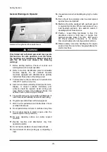
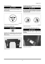
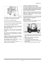
Page 31: ...Safety Section 29 Lean away from the direction of fall Lean forward...

Page 32: ...0 500 540 520 540 500 540 520 540 500 540 26 Speeds lowering loaded unloaded mm s 480 450 480 450 480 450 28 Drawbar pull at 1 6 km h loaded kg 3300 3355 3300 3430 3400 3410 30 Gradeability at 1 6 km...

Page 33: ...450 26 3300 3430 3300 3410 3400 3400 28 36 33 5 33 31 32 29 4 30 31 5840 6560 6560 32 8930 910 9860 1200 10380 1180 33 2810 3030 2725 3835 2725 3830 34 2 2 2 2 2 2 35 8 25X15 14 300X15 18 300X15 18 3...

Page 34: ...ERFORMANCE 24 traveling loaded unloaded km h 21 22 20 21 25 lifting loaded unloaded mm s 500 540 500 540 26 Speeds lowering loaded unloaded mm s 480 450 480 450 28 Drawbar pull at 1 6 km h loaded kg 3...

Page 35: ...561 571 22 20 21 20 21 24 500 540 500 540 25 480 450 480 450 26 3410 3410 28 30 7 30 7 30 6560 7035 32 9860 1200 10585 1450 33 2725 3835 2660 4375 34 2 2 2 2 35 300X15 18 300X15 18 36 7 00X12 12 7 00X...

Page 36: ...24 25 24 25 25 lifting loaded unloaded mm s 520 540 520 540 520 540 26 Speeds lowering loaded unloaded mm s 480 450 480 450 480 450 28 Drawbar pull at 1 6 km h loaded kg 3300 3300 3400 30 Gradeabilit...

Page 37: ...510 540 25 480 450 480 450 490 450 490 450 26 3300 3300 3400 3500 28 36 33 32 30 30 31 5840 6170 6560 7035 32 8930 910 9620 1050 10380 1180 10585 1450 33 2810 3030 2730 3440 2725 3830 2660 4375 34 2...

Page 38: ...86 5 81 82 108 D35 40 45S 2 D40 45 50SC 2 D50C 2 TIERIIE G W OCabin 81 7 83 7 78 3 77 4 107 G35 40 45S 2 G50C 2 G40 45 50SC 2 W OCabin NON CERT 84 9 87 5 85 85 108 G35 40 45S 2 G50C 2 TIERIIE G W OCa...

Page 39: ...General Section 37 Capacity Chart...

Page 40: ...General Section 38 Capacity Chart...

Page 41: ...General Section 39 Capacity Chart with Side Shifter...

Page 42: ...General Section 40 Capacity Chart with Side Shifter...

Page 43: ...General Section 41 Capacity Chart...

Page 44: ...General Section 42 Capacity Chart...

Page 45: ...General Section 43 Capacity Chart with Side Shifter...

Page 46: ...General Section 44 Capacity Chart with Side Shifter...

Page 47: ...General Section 45 Capacity Chart D G 50C 2...

Page 48: ...General Section 46 Capacity Chart with Side Shifter D G 50C 2...

Page 49: ..._________________________ 5 8 liter Diesel Engine TIER I Serial Number ______________________________ 5 8 liter Diesel Engine TIER II Serial Number ______________________________ 4 3 liter GM Vortec E...

Page 50: ...General Section 48 DRIVE AXLE Serial Number ______________________________ Side Shifter Serial Number If Equipped ______________________________...

Page 51: ...ck can lift 1200kg 2640lb if the load center is 600 mm 24in from both the vertical and horizontal faces of the forks Before attempting to lift any load ensure that the weight and load center combinati...

Page 52: ...cation plate a standard carriage and forks are used Attachment Abbreviations Includes Special Forks SC Special Carriage increased width height or outreach SSS Shaft type Sideshift Carriage HSS Hook ty...

Page 53: ...he illustrations Due to the various options available typical instrument panels are shown However the symbols on the indicators and lights on your panel identify what those particular items are Also t...

Page 54: ...end of the green band when the coolant temperature reaches approximately 106 C 223 F on all engines LED Type Gage If both tenth ninth flash out of phase while operating the lift truck overheating is...

Page 55: ...n push down switch to the first step The front and rear floodlights are ON when push down switch to the second step 18 Brake Fluid Oil Light If Equipped The light is ON when the brake fluid oil of bra...

Page 56: ...the latch and raising the hood and seat assembly NOTE Unlock latch before pulling if key equipped 2 The hood and seat assembly is held up by a support cylinder Make certain the air cylinder is operati...

Page 57: ...knob 1 Electrical Disconnect Switch If Equipped 1 ON Connects the battery for electrical power to all electrical circuits 2 OFF Disconnects the battery from all electrical circuits Seat NOTE Seat arr...

Page 58: ...ck with an alarm that will sound if the parking brake is not applied when leaving the machine NOTICE 1 Prior to operating the lift truck be sure to understand and check the SEAT SWITCH SYSTEM 2 While...

Page 59: ...the lever clockwise for LOW speed range Transmission Inching Control Pedal Inching Control Pedal Pushing down on the inching pedal modulates the hydraulic pressure to the clutch packs permitting disc...

Page 60: ...e Lever Pull the lever BACK to engage the parking brake Push the lever FORWARD to release the parking brake Lift Control NOTE To prevent a sudden change of position of the load operate all lift tilt a...

Page 61: ...ing action will stop 3 Mast Tilt Back Pull the lever BACK smoothly to tilt the mast backward Sideshift Attachment Control If Equipped 1 Sideshift Left Push the lever FORWARD to shift the carriage to t...

Page 62: ...laden air and to prevent condensation In the cold weather the moisture condensation can cause rust in the fuel system and hard starting due to its freezing Do not fill the tank to the top Fuel expands...

Page 63: ...not smoke in refueling areas Lift truck should be refueled only at designated safe locations Safe outdoor locations are preferable to indoor locations Stop the engine and get off the lift truck durin...

Page 64: ...plings for deterioration damage or missing flexible seals 11 Position the replacement tank so that the locating pin dowel is in place WARNING The LP Gas tank must not extend past the counterweight 12...

Page 65: ...ator lights or gauges 3 Test the horn and other safety devices for proper operation 4 Inspect the mast and lift chains for wear broken links pins and loose rollers 5 Inspect the carriage forks or atta...

Page 66: ...is empty also fill the radiator at the top tank 13 Observe the fuel level gauge after starting the truck Add fuel if necessary 14 In case of LPG truck if needed change LPG Fuel Tank as the procedure...

Page 67: ...cator light will come ON The preheat indicator light will stay ON approximately seven seconds depending on the surrounding air temperature NOTICE Do not engage the starter for more than 10 seconds 2 W...

Page 68: ...step 2 and depress the accelerator pedal slightly during cranking 4 Allow the engine to warm up slowly Starting From a 12 Volt External Source WARNING Sparks occurring near the battery could cause vap...

Page 69: ...e light comes ON with the engine running 3 The G643E engine MIL Malfunction Indicator Light 3 will not come ON with engine running unless the fault or faults are stored in the memory of the engine con...

Page 70: ...engines performance Engine speed is monitored by the SECM through a variable reluctance VR sensor Intake manifold air temperature and absolute pressure is monitored with a TMAP sensor The MI 04 is a d...

Page 71: ...n liquid valve Excess flow valve closed Reset excess flow valve z Close liquid valve z Wait for a click sound z Slowly open liquid valve Plugged fuel line Remove obstruction from the fuel line z Close...

Page 72: ...e z Using caution disconnect the fuel line some propane may escape z Clear obstruction with compressed air z Re connect fuel line z Slowly open liquid fuel valve z Leak test Faulty vapor connection be...

Page 73: ...connect fuel line z Slowly open liquid fuel valve Leak test Pressure regulator freezes Check level in cooling system z Must be full check coolant strength z 35F minimum Check coolant hoses z Watch fo...

Page 74: ...stics Will Not Accelerate Hesitatio n During Acceleration Engine Mechanical See Engine Service Manual Fuel container almost empty LPG Vapor from liquid outlet z Fill fuel container z Do not exceed 80...

Page 75: ...vice Manual Vacuum leak Check for vacuum leaks z Between mixer and throttle body z Between throttle body and intake manifold z Between intake manifold and cylinder head Air Fuel Mixer malfunction Chec...

Page 76: ...alve z Using caution disconnect the fuel line some propane may escape z Clear obstruction with compressed air z Re connect fuel line z Slowly open liquid fuel valve Leak test Air filter clogged Check...

Page 77: ...lator malfunction fuel pressure too high Test pressure regulator operation z See G643E Engine Service Manual Faulty FTV Check FTV for housing cracks or obstructions z See Advanced Diagnostics FTV oper...

Page 78: ...es are two digit codes When the fault codes are retrieved displayed the MIL will flash for each digit with a short pause 5 seconds between digits and a long pause 1 2 seconds between fault codes A cod...

Page 79: ...he foot pedal three 3 times within five 5 seconds to enable the display codes feature of the SECM Simply turn the key OFF to exit display mode The code list will continue to repeat until the key is tu...

Page 80: ...nd for leaks in the system Possible ECT short to GND check ECT signal wiring Check regulator for coolant leaks 22 ThrottleSensorInputLo TPS1 signal disconnected or open circuit Expected faults when ET...

Page 81: ...ansient manuevers It is not system trouble If the fault really sets then the engine will shut down 28 ETCSpringTestFailed Upon initial key up the internal throttle return spring has become weak Power...

Page 82: ...P PIN 2 to SECM PIN 4 SIGNAL TMAP PIN 1 to SECM PIN 1 GND TMAP PIN 3 to SECM PIN 18 XDCR 5VDC To check the IAT sensor of the TMAP disconnect the TMAP connector and measure the IAT resistance See the I...

Page 83: ...ge measured above 15 9 VDC Stored Fault Code MIL Only Check battery and charging system voltage Check battery voltage during starting and with the engine running Check voltage regulator alternator and...

Page 84: ...ditional ETC faults z Check for ETC Sticking or other ETC faults z Verify if the lift truck was motored down a steep grade 61 Pedal1SensorInputLo APP1 signal disconnected open circuit or sensor malfun...

Page 85: ...2 potentiometer malfunction Improper APP2 reading may be due to dirt or oxidation on the sensor traces Stored Fault Code MIL Only Check foot pedal connector 68 Pedal2SensorRangeHi APP2 potentiometer m...

Page 86: ...nifold leaks z Check balance line vacuum hose connection at the regulator z Check N CA55 500 TR mixer for heavy end build up and operation see mixer section z Check N2001 secondary for operation or lo...

Page 87: ...Adaptive learns Note If LP Gas fuel in LP tank is not enough this fault code can be set If LP tank is frozen this fault code can be set too It is not system trouble Check the FTV for proper operation...

Page 88: ...ion control lever in the NEUTRAL center position and apply the parking brake before dismounting the lift truck 5 Release the service brake 6 Push down on the accelerator pedal to obtain the desired tr...

Page 89: ...ake pedal and bring the lift truck to a smooth stop Inching NOTE The purpose of the inching pedal is to provide precise lift truck inching control at very slow travel speed and high engine rpm This is...

Page 90: ...ibit selecting direction at high speed outside of the design parameters Adjustments SW1 Low High Shift Point SW2 Direction Inhibit Point NOTCH Vehicle Speed NOTCH Vehicle Speed 0 2 5 km h 1 55 mph 0 3...

Page 91: ...rated in two preselected modes automatic mode and manual mode Automatic Mode is selected in factory setting controller as a default Manual Mode Fail Safe Mode is selected to operate the truck manually...

Page 92: ...by its own speed ratio control so that the appropriate gear may be engaged in every situation NOTICE Two Speed Auto Shift Control function can be accomplished only when the direction control lever is...

Page 93: ...rt as load permits Typical Example 2 Move the lift truck FORWARD until the load touches the carriage Lifting the Load 1 Lift the load carefully and tilt the mast back a short distance Typical Example...

Page 94: ...ll on upgrades and downgrades Typical Example 2 For better vision travel in reverse with bulky loads Unloading Typical Example 1 Move the lift truck into the unloading position Typical Example 2 Tilt...

Page 95: ...le 4 Lower the carriage and forks to the travel position or to the park position Turning 1 When turning sharp corners keep close to the inside corner Begin the turn when the inside drive wheel meets t...

Page 96: ...n hot weather Keep the following points in mind when you operate the lift truck in hot weather 1 Check the radiator Clogging can cause overheating Clean them out regularly with a blast of compressed a...

Page 97: ...he parking brake 4 Lower the forks to the ground WARNING Blocking the wheels will prevent unexpected lift truck movement which could cause personal injury 5 Turn the key in the ignition switch to the...

Page 98: ...position 2 Raise the hook pin in each fork to side the fork on the carriage bar 3 Adjust the forks in the position most appropriate for the load and as wide as possible for load stability 4 When adjus...

Page 99: ...er z Dismount the battery from the machine Even though the machine is parked indoors if the place is hot or humid the battery should be kept in a dry cool place Charge the battery once a month z Apply...

Page 100: ...uck Position the lift truck on the truck bed or the rail car Apply the parking brake and place the transmission control in NEUTRAL Turn the ignition switch to the OFF position and remove the key If LP...

Page 101: ...as low as possible on the lift truck that is being towed Quick lift truck movement could overload the tow line or bar and cause it to break Gradual and smooth lift truck movement will work better Norm...

Page 102: ...s equal to or greater than the Standard or rated Capacity of the lift truck The individual load rating in most cases will be stamped on the fork in a readily visible area This is generally on the top...

Page 103: ...d bearing cross section of the remaining metal is decreased in size until it becomes insufficient to support the load and complete failure occurs Fatigue failure is the most common mode of fork failur...

Page 104: ...the forks First Installation 1 Inspect forks to ensure they are the correct size for the truck on which they will be used Make sure they are the correct length and type for the loads to be handled If...

Page 105: ...ith a carbon stone to remove minor surface cracks or defects Polish the inside radius of the heel section to increase the fatigue life of the fork Always grind or polish in the direction of the blade...

Page 106: ...re cold inflation shipping pressures Shipping Pressure Size Ply Rating or Strength Index kPa psi 7 00X12 Steer 12 860 125 8 25X15 Drive 14 825 120 300X15 Drive 18 785 115 7 50X16 Drive dual 12 760 110...

Page 107: ...h N m 1 lb in 16 mm 625 in 7 5 0 5 65 5 13 5 mm 531 in 4 5 0 5 40 5 8 mm 312 in 0 9 0 2 8 2 Reassembly Or Retightening Torque Clamp Width N m1 lb in 16 mm 625 in 4 5 0 5 40 5 13 5 mm 531 in 3 0 0 5 25...

Page 108: ...t in personal injury Original fasteners removed from the lift truck should be saved for reassembly whenever possible If new fasteners are needed they must be of the same size and grade as the ones tha...

Page 109: ...shipped to an area with freezing temperatures the cooling system must be protected to the lowest expected outside ambient temperature The engine cooling system is normally protected to 28 C 20 F with...

Page 110: ...r use it mixed with antifreeze of different brand DOOSAN recommends that the coolant mix contain 50 commercially available automotive antifreeze or equivalent and acceptable water to maintain and adeq...

Page 111: ...nance costs and reduced engine service life Crude oil is used to describe oils fuels that are not refined and are in the original state as when pumped from the ground Certain types of crude oils can b...

Page 112: ...request fuel sulfur content information from your fuel supplier Fuel sulfur content can change with each bulk delivery LP Gas Specifications LP Gas is Liquefied Petroleum Gas The exact composition of...

Page 113: ...mmendations For fuel sulfur effects the Infrared Analysis or the ASTM D2896 procedure can be used to evaluate the residual neutralization properties of an engine oil The sulfur products formation depe...

Page 114: ...al requirements for disk materials and or excessive gear wear Select the oil that meets the following specification z GM DEXRON III z FORD MERCON V Drive Axle Oil NOTE Failure to follow the recommenda...

Page 115: ...r antifoam antirust and antioxidation additives for heavy duty use as stated by the oil supplier ISO viscosity grade of 32 would normally be selected The following products are authorized for use Supp...

Page 116: ...sc Brake OCDB UTTO UTTO 20 80 4 176 ISO VG32 20 30 4 86 ISO VG46 10 40 14 104 Brake Reservoir Only for OCDB ISO 6743 4HM ISO VG68 0 50 32 122 The SAE grade number indicates the viscosity of oil A prop...

Page 117: ...el Check 139 Drive Axle Oil Level Check 139 Mast Carriage Lift Chains Attachments Check Lubricate 140 Carriage Side Rollers Lubricate 141 Steering Mechanism Check Lubricate 141 Battery Terminal Clean...

Page 118: ...ock off Operation LP Gas Engine Only 158 Every 2000 Service Hours or Yearly Steer Wheel Bearings Reassemble 159 Cooling System Clean Change 161 Fork Inspect 162 Every 2500 Service Hours or 15 Months H...

Page 119: ...r Change 142 148 O O Engine Oil Oil Filter Diesel E G Only Change 129 O Engine Oil Level Clean Check 125 O Engine Valve Lash Diesel E G Only Check Adjust 118 O Forks Inspect 162 O Fuel Filter Change 1...

Page 120: ...rns Allow additional time for the engine to cool before measuring valve clearance NOTICE Measure the valve lash with the engine stopped To obtain an accurate measurement allow at least 20 minutes for...

Page 121: ...en perform a visual inspection of the fuel system Leaks will cause the solution to bubble 5 Repair any leaks before continuing 6 Crank the engine through several revolutions This will energize the fue...

Page 122: ...ertical until completely remove an air 4 Tighten air bleed nut 2 5 Make sure to check leakage of injection pump filter after operating feed pump many times Seat Hood Latch Support Cylinder Check Lubri...

Page 123: ...over from the fuse box The fuses are located under the cowl Fuse Protects an electrical circuit from an overload Opens filament separates if an overload occurs Fuse Box Open Typical Example Fuse Box C...

Page 124: ...n 24V 55W 2 Bulb back up 24V 10W 3 Bulb turn signal 24V 25W 4 Bulb stop tail 24V 25 10W LP Gas Engine 1 Bulb head lamp halogen 12V 35W 2 Bulb back up 12V 8W 3 Bulb turn signal 12V 23W 4 Bulb stop tail...

Page 125: ...rims the assemblies could burst with explosive force and cause serious physical injury or death Follow carefully the specific information provided by your tire servicing man or dealer Check Inflation...

Page 126: ...attempt to rework weld heat or braze any rim components Carriage Roller Extrusion Check Adjust 1 Set the mast vertical 2 Lower the carriage completely 3 On full free lift and full free triple lift mo...

Page 127: ...y Make certain the support cylinder securely holds the hood open 2 Maintain oil level between the MAX and MIN marks on the dipstick Coolant Level Check Clean Check Coolant Level WARNING At operating t...

Page 128: ...Indicator Typical Example Diesel Engine Truck Typical Example LP GasEngine Truck 1 Observe the air cleaner service indicator 2 Service the air cleaner when the RED band in the service indicator lock i...

Page 129: ...lift chains for wear broken links pins and loose rollers 3 Inspect the hydraulic system for leaks worn hoses or damaged lines 4 Look for transmission and differential leaks on the lift truck and on t...

Page 130: ...onents can cause personal injury Do not allow hot oil or components to contact skin 1 Start and operate the lift truck until the engine reaches normal operating temperature 2 Park the lift truck level...

Page 131: ...the engine stopped 2 Raise rear of lift truck off ground and block securely WARNING Hot oil and components can cause personal injury Do not allow hot oil or components to contact skin Typical Example...

Page 132: ...NING Hot oil and components can cause personal injury Do not allow hot oil or components to contact skin Park the lift truck level with the forks lowered parking brake engaged transmission in NEUTRAL...

Page 133: ...fill Capacities Install the dipstick filter cap 9 Start the engine 10 With the service brake applied and engine at low idle shift the transmission to forward and reverse to fill the clutches 11 Shift...

Page 134: ...rains Remove the drain plug 3 Allow the oil to drain completely out Discard the oil according to local regulations 4 Clean and reinstall the drain plug 5 Remove the oil level plug 6 Add sufficient fre...

Page 135: ...all the dip stick filter cap Parking Brake Test Adjust NOTE Be sure area around the lift truck is clear of personnel and obstructions 1 Drive the lift truck with a capacity load forward up a 15 inclin...

Page 136: ...th the forks lowered transmission in NEUTRAL the engine stopped and the wheels securely blocked 1 Release the parking brake 2 Turn the adjustment knob clockwise to tighten the brake 3 Test the parking...

Page 137: ...nents to contact skin Park the lift truck level with the forks lowered parking brake engaged transmission in NEUTRAL and the engine stopped 1 Raise the hood and seat assembly Loosen the bolts of the h...

Page 138: ...Truck Typical Example LP Gas Engine Truck 1 Check the precleaner bowl for dirt build up If the dirt is up to the line remove the precleaner bowl and empty it Periodically wash the cover and bowl in w...

Page 139: ...or replace parts as necessary to prevent leakage NOTICE Do not allow dirty air to enter the intake hose when cleaning the inside of the air cleaner housing 5 Check the air cleaner housing for loose l...

Page 140: ...hand to use while cleaning used elements The primary element should be replaced after a year s service or after cleaning no more than 6 times Air 205 kPa 30 psi Maximum Pressure Direct air on the ins...

Page 141: ...mbly Make sure the air lift cylinder securely holds the hood open 3 Remove the dipstick filter cap Maintain the oil level to the FULL mark on the breather dip stick Drive Axle Oil Level Check WARNING...

Page 142: ...te a need for repair 2 Inspect for loose bolts and nuts on the carriage Remove any debris from the carriage and mast 3 Inspect the forks and attachments for free operation and damage Have repairs made...

Page 143: ...or inserting washer Carriage Side Rollers Lubricate D35 40S 2 D40 45SC 2 G35 40S 2 G45 50SC 2 D45S 2 D50SC 2 D50C 2 G45S 2 G50SC 2 Lubricate 2 side roller fittings one on each side of the carriage Ste...

Page 144: ...topic Engine Oil Filter Diesel Engine Only Change in First 50 100 Service Hours LP Gas Engine Crankcase 1 Operate lift truck a few minutes to warm oil Park the lift truck with the forks lowered parki...

Page 145: ...ubricate ball seas of wheels or ball faces of wheel nuts Be sure mounting faces of hub wheel nuts and flat mounting surfaces are clean Tighten wheel nuts again after 24 hours of operation NOTE Always...

Page 146: ...under 110N of force NOTICE Failure to loosen the alternator mounting bolt will cause excessive stress and break the alternator mounting gear 3 To adjust the alternator drive belt loosen adjusting bra...

Page 147: ...d To adjust back tilt spacers must be added or removed Typical Example 1 Check to make sure the tilt cylinders extend and retract evenly 2 If one cylinder continues to move after the other cylinder ha...

Page 148: ...the carriage high enough to gain access to the side thrust rollers on the back side of the carriage Block the carriage in this position 2 Lubricate 2 side thrust roller fittings one on each side of t...

Page 149: ...nut 4 4 Lower the hood and seat assembly Drive Axle Oil Strainer OCDB Only Check Clean Change WARNING Hot oil and components can cause personal injury Do not allow hot oil or components to contact ski...

Page 150: ...hts If Equipped Check 1 Press horn button to determine if horn is operational 2 Check and replace all defective gauges 3 Check all lights such as warning directional backup driving and flood lights fo...

Page 151: ...V when de energized replace the FTV Inspect Electrical System G643E Engine only 1 Check for loose dirty or damaged connectors and wires on the harness including Fuel lock off TMAP sensor O2 sensor Ele...

Page 152: ...ne stopped For the complete procedure and specifications for your specific engine see the Service Manual Fuel Filters Change Diesel Engine Park the lift truck with the forks lowered parking brake appl...

Page 153: ...RED after installing a new secondary element and a cleaned primary outer element replace the cleaned primary filter with a new element 5 Stop the engine Close the hood and seat assembly Inspect Coolan...

Page 154: ...ixer and throttle section of the service manual for procedures on removing the mixer and inspecting the throttle plate Hydraulic Return Filter Change See topic Hydraulic Return Filter Change in First...

Page 155: ...le 2 Measure precisely ten links of chain distance at the center of pins in millimeter 3 Calculate chain wear rate 4 If the chain wear rate is 2 or more replace the lift chain Chain wear rate Actual m...

Page 156: ...chain tension If not equal repeat the same procedure as step 1 through step 3 5 Put LOCTITE No 242 Tread lock on the threads of the anchor nuts 1 2 after the adjustment is completed Mast Chain Adjust...

Page 157: ...enance Section 155 Universal Joint Diesel Engine Only Inspect 1 Inspect for loose retaining bolts Check for worn or damaged bearings 2 Have worn or damaged bearings replaced Tighten the bolts if neces...

Page 158: ...an 25 kOhms repair and or replace 4 Remove distributor cap and perform visual inspection Replace cap and rotor if corrosion is found on the contacts 5 Inspect the ignition coil for cracks and heat det...

Page 159: ...lter LP Gas Engine Only Disassembly 1 Remove top cover 2 magnet 3 spring 4 and filter element 7 from bottom cover 5 2 Replace the filter element 7 3 Check bottom cover O ring seal 6 for damage Replace...

Page 160: ...time 5 Turn the ignition key switch off and re connect the fuel lock off connector NOTE The length of time the engine runs on trapped fuel vapor increases with any increase in distance between the fu...

Page 161: ...ds or blocking under the frame and steer axle to support the lift truck 2 Remove the hub cap Typical Example 3 Remove the cutter pin 4 Remove the castle nut and washer 5 Remove the wheel assembly Exam...

Page 162: ...cknut to 135 N m 100 lb ft while turning wheel hub to seat the bearing 10 Loosen the locknut Retorque it to 50 5 N m 37 4 lb ft Bend the lockwasher tang to secure locknut 11 Install the hub cap 12 Rai...

Page 163: ...ow the coolant to drain Drain the recovery bottle 4 Close radiator drain valve and install block drain plug Fill the cooling system with 1 kg 2 lb sodium bisulphate per 40 liters 10 gallons of water M...

Page 164: ...ork should be withdrawn from service if angle C exceeds 93 degrees or deviates by more than 3 degrees from an original angle other than 90 degrees as may be found in some special application forks 3 C...

Page 165: ...revented from sliding off the end of the carriage by stop blocks These stop blocks are at both ends of the carriage and in the path of the bottom fork hook The load backrest extension may be used in p...

Page 166: ...d back all cylinders retracted parking brake engaged transmission in NEUTRAL and the engine stopped 1 Remove the hydraulic tank drain plug Allow the oil to drain Clean and install the plug 2 Raise the...

Page 167: ...eplace as necessary 4 Apply a thin coat of an approved silicon lubricant to the TMAP o ring seal 5 Re install the TMAP sensor into the manifold adapter and securely tighten the retaining screw 1 LP fu...

Page 168: ...643E Engine Only 1 Stop engine and wait until the exhaust pipe and exhaust pipe is cooled 2 Disconnect the electrical connector of oxygen sensor 3 Remove oxygen sensor 4 Assemble new oxygen sensor Tig...

Page 169: ...Secondary Element 151 Chassis Pivot Eyebolts 145 Check Coolant Level 125 Check for Equal Tension 153 Check Inflation and Damage 123 Checking Element 138 Checking Service Indicator 126 Checking the TMA...

Page 170: ...eck Clean Change 164 Hydraulic Oil HYDO 111 Hydraulic Oil Level Check 139 Hydraulic Return Filter Change 135 152 Identification Lift Capacity and Attachment Plate 49 If Optional Suspension Seat weight...

Page 171: ...Operator s Warning and Identification Plate 49 Overhead Guard Inspect 149 Overhead Guard Must Be In Place Warning 8 Overloading 101 P Parking brake 9 Parking Brake Test Adjust 133 147 Parking Brake Le...

Page 172: ...tandard Hose Clamps Worm Drive 105 Torque Specifications 105 Torques for Bolts and Nuts With Standard Threads 105 Torques for Taperlock Studs 106 Towing Information 99 Training Required to Operate or...

Reviews: