background image

Service Manual

Video Cassette Recorder

All models (K30 -Mecha)
SYSTEM : NTSC

Model : DV-K892NZ-QB/M    
               DV-K592NZ-QB/M    

DAEWOO ELECTRONICS CO., LTD.

http : //svc.dwe.co.kr

S/M No. : VK592NTEF0

Summary of Contents for DV-K892NZ-QB/M

Page 1: ...Service Manual Video Cassette Recorder All models K30 Mecha SYSTEM NTSC Model DV K892NZ QB M DV K592NZ QB M DAEWOO ELECTRONICS CO LTD http svc dwe co kr S M No VK592NTEF0...

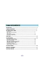
Page 2: ...T 4 HEAD MODEL 21 WAVEFORMS 24 CIRCUIT DIAGRAM 28 INTERCONNECT WIRING DIAGRAM 28 POWER SUPPLY SCHEMATIC DIAGRAM 29 SYSCON CIRCUIT DIAGRAM 30 VIDEO AUDIO SCHEMATIC DIAGRAM 4 HEAD 31 VIDEO AUDIO SCHEMAT...

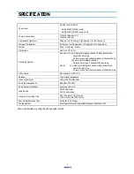
Page 3: ...scan Luma FM recording Chroma converted subcarrier phase shifted recording Two audio record playback heads Rotary helical scan 2 channels FM recording 4 head Four video record playback heads Rotary he...

Page 4: ...scope on channel 1 3 Connect channel 2 scope probe 1V div to the Video Out Jack 4 Set the scope to slope and adjust the PG Shifter control R595 so that the trailing edge of the SW 30Hz pulse is place...

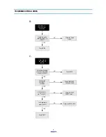
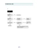
Page 5: ...ltage applied to the terminal of C806 Is output voltage of secondary correct Check secondary rectifier Diode D809 D810 D812 D819 Is sw pulse of base T801 Correct OK Change AC CORD Check Ic601 Check IC...

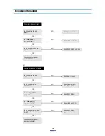
Page 6: ...601 pin of IC601 Is 5V applied to pin of IC601 Is 4V applied to collector of Q711 Q712 Q713 and Q714 Check IC602 Check D813 Check IC601 Check R636 C616 Check Q711 Q712 Q713 and Q714 YES YES YES YES NO...

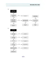
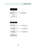
Page 7: ...t pin of IC601 Do pin and of IC601 oscillate Check IC601 Check C820 Check X601 R603 C604 and C605 NO YES YES YES YES NO NO NO B C Check the IC602 RESET circuit Is 0V applied to pin of Ic601 YES NO Che...

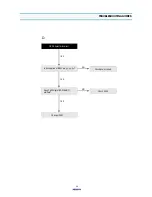
Page 8: ...output signal pin of IC301 YES YES NO NO YES E Is 5V supplied to pin of Ic601 NO YES Is 5V applied to pin of Ic601 YES Check X601 Is 4V applied to the collector Is 5V applied to of Q711 Q712 Q713 Q714...

Page 9: ...pin of IC601 YES NO NO Check IC601 NO Noise appears although change cassette tape CTL HEAD height is normal and there is not dust YES Check CTL input in circuit R501 R502 R503 C501 CTL AMP VREF IC601...

Page 10: ...nve waveform supplied to at pin of PT01 YES NO Check VIDEO circuit Check connector Head Amp and Clean heads Is Reel pulse applied to pin and of IC601 YES NO YES NO Check REEL sensor part Is D FG appli...

Page 11: ...or J YES YES Check power circuit NO Is 12V supplied to P501 pin YES NO Is the voltage of pin P501 3 2V YES Check R513 R514 NO Is the voltage of P501 pin 2 5V YES Check IC601 and C FG NO Is C PWM pin o...

Page 12: ...Err 82 84 86 66 Is 12V applied to pin of IC604 Check power circuit YES NO L Check motor drive circuit Check IC601 Is 5V applied to pin of IC601 when CST IN YES NO Is 5V applied to pin of PJ601 when C...

Page 13: ...om pin of Ic301 YES NO Check IIC CLK DATA Is 5V suppiled to pin and of Ic601 Check PCB pattern Is signal input into pin of Ic601 YES NO Is signal output from pin of Ic601 YES NO YES Check power circui...

Page 14: ...eparated C signal output from pin of IC301 input into pin of IC301 output from pin of IC301 YES Is composite video signal output from pin of IC301 YES Check OSD circuit NO NO YES NO YES NO NO NO NO NO...

Page 15: ...IC401 pin Is REC H signal supplied IC301 pin Is SW pulse input into IC301 pin Is REC signal output from IC301 pin SP mode pin EP mode pin Check video head and connector Check EE mode Is signal input...

Page 16: ...15 TROUBLESHOOTING GUIDES YES D Does X602 crystal 14 318MHz oscillate YES NO Is 5V supplied at IC601 pin YES NO Check power circuit OSD Character Incorrect Check X602 Change IC601 53 98 99...

Page 17: ...O A Is 5V supplied to pin of IC251 and pin of IC301 Check INPUT JACK Is signal input pin of IC251 in line mode YES NO Is 0V supplied to pin of IC251 YES NO YES NO Check SYSCON circuit Change IC251 Is...

Page 18: ...vel of IC251 pin more than 200mVp p Is A SW PULSE input into pin of IC251 Is pin of IC251 over 3V Check IC601 NO Check the PRE AMP circuit NO Check IC601 Change IC251 YES YES YES No Hi Fi sound in pla...

Page 19: ...of Q205 5V NO NO Check IC601 Is there output at pin of IC251 Clean HEAD Is there FM osc wave at pin of P401 NO Check IC251 NO Change Drum YES YES YES YES No Hi Fi sound in the playback mode after Hi F...

Page 20: ...in of IC301 NO Is 9V supplied pin of IC251 NO Check Power circuit Is there Audio signal pin of IC301 Is pin of IC301 0V NO Check A C head Check PJ201 and A C head NO NO Check Power circuit YES YES YES...

Page 21: ...Is the voltage above 5 8V at pin of T201 Is the Emitter of Q205 5V YES NO Check power circuit NO YES Check A C HEAD and connector pin of PJ201 Check INPUT JACK NO Check power circuit YES YES YES Chec...

Page 22: ...o pin of IC301 Check power circuit YES NO A Check INPUT JACK Is signal input pin of IC301 in line mode YES NO Is 0V supplied to pin of IC301 YES NO YES Check SYSCON circuit Change IC301 Is there outpu...

Page 23: ...t pin of IC301 Check R214 R265 C279 Is 5V applied to pin of IC301 Is IIC CLK applied to pin of IC301 Is the collector of Q203 0V Check Pin of PJ201 NO NO Check power circuit NO Check IC601 NO Check Q2...

Page 24: ...ES NO Check Q202 YES Is there output at pin of IC301 Does T201 oscillate YES YES Check A C HEAD and connector pin of PJ201 Check Q202 Collect 5 8V Base 0 7 3 0V NO Check T201 Check INPUT JACK YES Is t...

Page 25: ...21 500mVp p 200mV 10u sec cm PLAY IC301 41 150mVp p 50mV 10u sec cm PLAY IC301 28 5 2Vp p 2V 5msec cm Picture search 2 5 7 9 IC301 12 300mV 100mV 10u sec cm REC 3 IC301 20 500mVp p 200mV 10u sec cm R...

Page 26: ...PLAY 12 IC301 61 300mVp p 200mV 10u sec cm REC PLAY 13 IC301 59 300mVp p 200mV 10u sec cm REC PLAY 14 IC301 76 100mVp p 20mV 0 5msec cm REC IC301 100 120mVp p 50mV 0 5msec cm PLAY 16 20 IC301 96 1 5V...

Page 27: ...C601 38 4 8Vp p 1V 0 05u sec cm REC PLAY 23 27 31 IC601 77 5 5Vp p 2V 0 2u sec cm REC PLAY IC601 89 1 3Vp p 0 5V 0 5m sec cm REC PLAY 24 28 IC601 76 5Vp p 2V 0 2u sec cm REC PLAY 25 IC601 90 2Vp p 0 5...

Page 28: ...C251 61 0 8Vp p 0 2V 0 5msec EE REC PLAY IC251 39 0 75Vp p 0 2V 0 5msec EE REC 32 36 IC251 12 0 75Vp p 0 2V 0 5msec EE REC IC251 57 0 9Vp p 0 2V 0 5msec EE REC 33 37 IC251 26 0 3Vp p 0 1V 1msec REC 34...

Page 29: ...28 CIRCUIT DIAGRAM 1 INTERCONNECT WIRING DIAGRAM...

Page 30: ...29 CIRCUIT DIAGRAM 2 POWER SUPPLY SCHEMATIC DIAGRAM...

Page 31: ...30 CIRCUIT DIAGRAM 3 SYSCON CIRCUIT DIAGRAM...

Page 32: ...31 CIRCUIT DIAGRAM 4 VIDEO AUDIO SCHEMATIC DIAGRAM 4 HEAD...

Page 33: ...32 CIRCUIT DIAGRAM 5 VIDEO AUDIO SCHEMATIC DIAGRAM HI FI...

Page 34: ...33 CIRCUIT DIAGRAM 6 PIF SCHEMATIC DIAGRAM 4 HEAD 68 16 4...

Page 35: ...34 CIRCUIT DIAGRAM 7 HI FI SCHEMATIC DIAGRAM...

Page 36: ...35 CIRCUIT DIAGRAM 8 PIF MPX SCHEMATIC DIAGRAM HI FI 68 16...

Page 37: ...36 PCB CIRCUIT BOARD MAIN PCB...

Page 38: ...presented When reassembling use the reverse procedure Make sure that all leads wiring are routed correctly when reassembling 1 Top Cover Removal Fig 1 1 Remove three 3 screws Holding the top cover 2 C...

Page 39: ...Front Panel Removal Fig 2 1 Continued from Fig 1 2 Remove two 2 screws securing front panel F L bracket 3 Remove the F L bracket 4 Release seven 7 tabs holding the front panel Release bottom tabs fir...

Page 40: ...39 INSTRUMENT DISASSEMBLY 3 Bottom Cover Removal Fig 3 1 Remove the top cover and the front panel 2 Remove two 2 screws 3 Lift out the bottom cover in the direction of the arrow...

Page 41: ...40 INSTRUMENT DISASSEMBLY 4 F L Door Removal Fig 4 1 Open the F L door 90 degrees 2 Remove the F L door in the direction of the arrow...

Page 42: ...Assembly Removal Fig 5 1 Remove the top cover the front panel and the bottom cover 2 Disconnect the FPC A 3 Disconnect three 3 connectors B C D 4 Remove four 4 screws E F 5 Pull out the Deck Assembly...

Page 43: ...UMENT DISASSEMBLY 6 Main PCB Assembly Removal Fig 6 1 Remove the top cover the front panel the bottom cover and the deck assembly 2 Release two 2 tabs A and lift out the Main PCB in the direction of t...

Page 44: ...20V C ELECTRO 25V RSS 22MF 5X11 C203 CMXM2A272J C MYLAR 100V 2700PF J TP C204 HCBK102KCA C CHIP CERA 50V X7R 1000PF K 2012 C205 HCFK104ZCA C CHIP CERA 50V Y5V 0 1MF Z 2012 MONO C206 CEXF1E330V C ELECT...

Page 45: ...34 HCFK104ZCA C CHIP CERA 50V Y5V 0 1MF Z 2012 NO PART CORD PART NAME PART DISC REMARK C335 HCFK223ZCA C CHIP CERA 50V Y5V 0 022MF Z 2012 C336 CEXF1C101A C ELECTRO 16V RSM 100MF 6 3X7 TP C337 CBZP1C10...

Page 46: ...1F TAPING C822 CEXF1E470V C ELECTRO 25V RSS 47MF 5X11 TP C823 CEXF1E470V C ELECTRO 25V RSS 47MF 5X11 TP C824 CEXF1E470V C ELECTRO 25V RSS 47MF 5X11 TP NO PART CORD PART NAME PART DISC REMARK C825 CEX...

Page 47: ...LU BLK L202 5CPX680J2T COIL PEAKING 68UH BLU BLK NO PART CORD PART NAME PART DISC REMARK L252 5CPX680J2T COIL PEAKING 68UH BLU BLK Hi Fi L302 5CPZ560K02 COIL PEAKING 56UH K AXIAL 3 5MM L304 5CPX100J2T...

Page 48: ...ARK R208 85801060TA WIRE COPPER 0 6X52MM TAPING Hi Fi RD AZ681J R CARBON FILM 1 6 680 OHM J MONO R209 HRFT273JCA R CHIP 1 10 27K OHM J 2012 MONO R210 RD AZ224J R CARBON FILM 1 6 220K OHM J MONO R211 R...

Page 49: ...RD AZ152J R CARBON FILM 1 6 1 5K OHM J R378 RD AZ155J R CARBON FILM 1 6 1 5M OHM J NO PART CORD PART NAME PART DISC REMARK R380 RD AZ101J R CARBON FILM 1 6 100 OHM J R501 HRFT332JCA R CHIP 1 10 3 3K O...

Page 50: ...29J R WIRE WOUND 2W 2 2 OHM J R803 HRFT103JCA R CHIP 1 10 10K OHM J 2012 NO PART CORD PART NAME PART DISC REMARK R804 HRFT689JCA R CHIP 1 10 6 8 OHM J 2012 R805 RS01F334J R M OXIDE FILM 1W 330K OHM J...

Page 51: ...SW TACT SKHV10914B 9 5M AUTO NO PART CORD PART NAME PART DISC REMARK SW704 5S50101Z97 SW TACT SKHV10914B 9 5M AUTO SW705 5S50101Z97 SW TACT SKHV10914B 9 5M AUTO SW706 5S50101Z97 SW TACT SKHV10914B 9...

Reviews: