background image


SERVICE


MANUAL


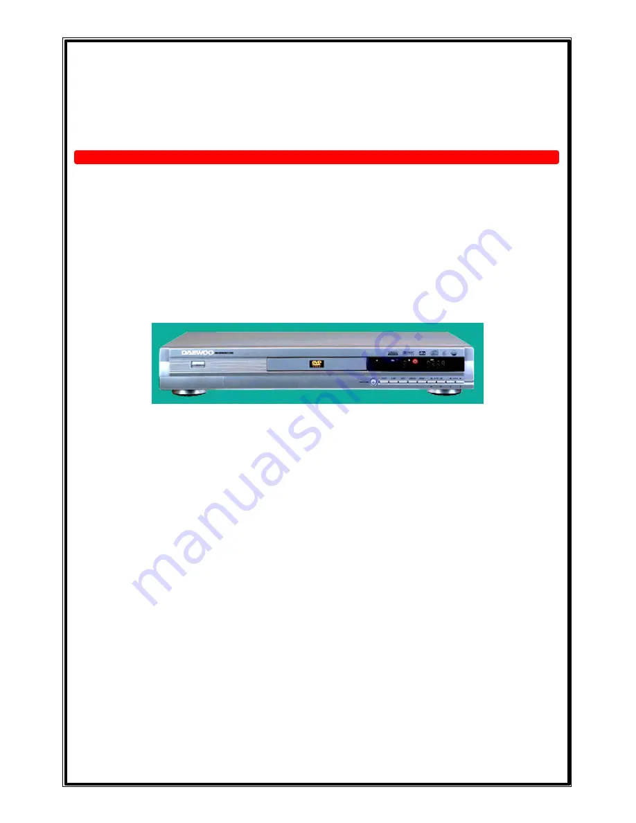
D V C-T 6 3 0 0 N   

For version 2 

1. Precautions 
2. Reference Information 
3. Product Specification 
4. Operating Instructions 
5. Disassembly and Reassembly 
6. Troubleshooting 
7. Electrical Part List 
8. Block Diagram 
9. PCB Diagrams 

10. Wiring Diagram 

11. Schematic Diagrams


12. Oscillograms


Component descriptions 

Summary of Contents for DVC-T6300N

Page 1: ...s 2 Reference Information 3 Product Specification 4 Operating Instructions 5 Disassembly and Reassembly 6 Troubleshooting 7 Electrical Part List 8 Block Diagram 9 PCB Diagrams 10 Wiring Diagram 11 Schematic Diagrams 12 Oscillograms Component descriptions ...

Page 2: ...h American National Standards institute ANSI C101 1 Leakage Current for Appliances and Underwriters Laboratories UL 1270 40 7 With the instrument s AC switch first in the ON position and then in the OFF position measure from a known earth ground metal water pipe conduit etc to all exposed metal parts of the instrument antennas handle brackets metal cabinets screwheads metallic overlays control sha...

Page 3: ...5 antenna wiring Always inspect in all areas for pinched out of place or frayed wiring Do not change spacing between a component and the printed circuit board Check the AC power cord for damage 5 Components parts and or wiring that appear to have overheated or that are otherwise damaged should be replaced with components parts and or wiring that meet original specifications Additionally determine ...

Page 4: ...e indicated or printed on the cabinet chassis or components When servicing follow the printed or indicated service precautions and service materials 3 The components used in the unit have a specified flame resistance and dielectric strength When replacing components use components which have the same ratings Components I enti fied by shading by or by in the circuit diagram are important for safety...

Page 5: ...a grounded tip soldering iron to solder or unsolder ESD device 4 Use only an anti static solder removal devices Some solder removal devices not classified as anti static can generate electrical charges sufficient to damage ESD devices 5 Do not use freon propelled chemicals These can generate electrical charges sufficient to damage ESD devices 6 Do not remove a replacement ESD device from its prote...

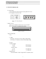
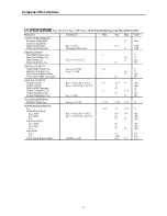
Page 6: ...ng its pin definition 39 1 40 2 Interface Connector Electrical Charateristics 1 Power 1 1 Voltage 5V DC with 5 tolerance less than 100mVp p Ripple Voltage 12V DC with 10 tolerance less than 150mVp p Ripple Voltage 1 2 Current Continuous Reading 5V DC 500mA Average 12V DC 300mA Average Seeking Spin up 5V DC 0 8 A Maximum 12V DC 1 5 A Maximum 2 Signal Summary The physical interface consists of singl...

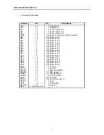
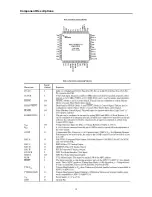
Page 7: ...a bus bit 5 DD6 5 I O Data bus bit 6 DD7 3 I O Data bus bit 7 DD8 4 I O Data bus bit 8 DD9 6 I O Data bus bit 9 DD10 8 I O Data bus bit 10 DD11 10 I O Data bus bit 11 DD12 12 I O Data bus bit 12 DD13 14 I O Data bus bit 13 DD14 16 I O Data bus bit 14 DD15 18 I O Data bus bit 15 DIOR 25 I I O read DIOW_ 23 I I O write DMARK_ 29 I DMA acknowledge DMARQ_ 21 O DMA request INTRQ 31 O Interrupt request ...

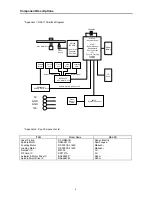
Page 8: ... Rohm Spindle Motor Drive IC BA6664FM Rohm Spindle Motor Focus Coil Track Coil Sled Motor Loading Motor BA6664FM Spindle Motor Drive BA5954FP 4Ch Motor Drive 80C52 System Controller Flash Memory 1Mbit MT1366 RF AMP Laser Driver Equalizer Error Gen Disc Motor Unit Laser Pickup MT1368 Decoder Servo ATAPI Buffer Manager Demodulator Error Correction PLl Focus Tracking Feeding Loading DRAM 4Mbit Spindl...

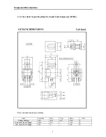
Page 9: ... Item Symbol Min Typ Max Unit Supply Voltage Vcc 4 75 5 0 5 25 V High Level Input Voltage VIH 2 0 Vcc V Low Level Input Voltage VIL 0 0 8 V 2 1 2 Fiber Optic Transmitting Module for Digital Audio Equipments VST5B Component Descriptions ...

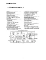
Page 10: ...10 2 1 3 NTSC PAL Digital Video Encoder AD7170 Component Descriptions ...

Page 11: ...11 Component Descriptions ...

Page 12: ...12 Component Descriptions ...

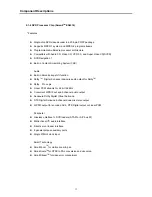
Page 13: ...r 24 bit 96KHz l Concurrent S PDIF out and 2 channel audio output l Sensaura Dolby Digital Virtual Surround l DTS Digital Surround 2 channel downmix stereo output l S PDIF output for encoded AC 3 DTS Digital output or Linear PCM Peripheral l Glueless unterface to DVD loaders ATAPI or A V bus I F l Bidirectional I 2 C audio interface l Direct servo loader interface l 8 general purpose auxiliary por...

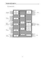
Page 14: ...14 Functional Description Component Descriptions ...

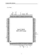
Page 15: ...15 Component Descriptions Pinout Diagram ...

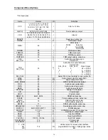
Page 16: ...he table for pin number 33 MCLK 39 I O Audio master clock for audio DAC TBCK 40 I O Audio transmit bit clock SDIF_DOBM 41 O S PDIF IEC958 Format Output RSD 45 I Audio receive serial data RWS 46 I Audio receive frame synch RBCK 47 I Audio receive bit clock APLLCAP 48 I Analog PLL Capacitor XIN 49 I Crystal input XOUT 50 O Crystal output DMA 11 0 66 61 58 53 O DRAM address bus DCAS 69 O Column addre...

Page 17: ... Interface Acknowledge Signal active low HRD DCI_C LK 150 I I Host read DCI Interface Clock HD 15 0 141 140 137 131 128 122 I O Host data bus HWRQ 142 O Host write request HRDQ 143 O Host read request HIRQ 144 I O Host interrupt HRST 145 O Host reset HIORDY 146 I Host I O ready HWR 149 O Host write request AUX 7 0 169 165 162 160 I O Auxiliary ports LOE 170 O Device output enable active low LCS 3 ...

Page 18: ...18 Block Diagram Component Descriptions 2 1 5 DIGITAL TO ANALOG STEREO AUDIO CONVERTER CS4391 ...

Page 19: ...19 Component Descriptions ...

Page 20: ...20 Component Descriptions ...

Page 21: ...21 Component Descriptions ...

Page 22: ...B program memory address space 64 KB data memory address space Four 8 bit bi directional ports Three 16 bit timer counters One full duplex serial port UART Watchdog Timer Eight sources two level interrupt capability EMI reduction mode Built in power management Code protection mechanism Packages DIP 40 W78LE52 24 Pin Configurations 2 1 6 8 BIT MTP MICROCONTROLLER W78LE52 ...

Page 23: ...O port which also provides a multiplexed low order address data bus during accesses to external memory The pins of Port 0 can be individually configured to open drain or standard port with internal pull ups P1 0 P1 7 PORT 1 Port 1 is a bi directional I O port with internal pull ups The bits have alternate functions which are described below T2 P1 0 Timer Counter 2 external count input T2EX P1 1 Ti...

Page 24: ...am Absolute Maximum Ratings PARAMETER SYMBOL MIN MAX UNIT DC Power Supply VDD VSS 0 3 7 0 V Input Voltage VIN VSS 0 3 VDD 0 3 V Operating Temperature TA 0 70 C Storage Temperature TST 55 150 C Component Descriptions ...

Page 25: ...ansfer Protocol 100 kHz 1 8V 2 5V 2 7V and 400 kHz 5V Compatibility Write Protect Pin for Hardware Data Protection 8 Byte Page 1K 2K 16 Byte Page 4K 8K 16K Write Modes Partial Page Writes Are Allowed Self Timed Write Cycle 10 ms max High Reliability Endurance 1 Million Write Cycles Data Retention 100 Years ESD Protection 3000V Automotive Grade and Extended Temperature Devices Available 8 Pin and 1...

Page 26: ...26 Component Descriptions Pin Configurations Pin Description Pin Name Function A0 A2 Address Inputs SDA Serial Data SCL Serial Clock Input WP Write Protect NC No Connect ...

Page 27: ...27 Component Descriptions 2 1 8 512K Bit CMOS 5 0 Volt only Uniform Sector Flash Memory A29040 ...

Page 28: ...28 Component Descriptions ...

Page 29: ...29 Component Descriptions 2 1 9 64MBit SDRAM 1MX 16BitX4Banks Synchronous DRAM LVTTL K4S641632D ...

Page 30: ...30 Component Descriptions ...

Page 31: ...31 Component Descriptions ...

Page 32: ... 1 Vpp 75 ohm S Video Out Y 1 Vpp 75 ohm C 0 286 Vpp 75 ohm Component Out 0 7 Vpp 75 ohm D A Converter 27MHz 10bit n Audio Performance Frequency Response DVD fs 48 96KHz 4Hz 2 44KHz Video CD fs 44 1KHz 4Hz 20KHz Audio CD fs 44 1KHz 4Hz 20KHz Output Level Analog 2Vrms 1 KHz Digital 1 15 Vpp D A Converter 96KHz 24bit S N Ratio 110 dB 3 Product Specifications ...

Page 33: ... X1 Audio Analog out for 2 channel X1 Component Video X1 Composite Video out X1 S Video out X1 n Power Supply Power Source AC 100 240V 50 60Hz Power Consumption 20 Watt n Set Dimensions W X H X D 440 X 60 X 270 mm Net Weight 3 2 Kg Gross Weight 4 Kg Product Specifications ...

Page 34: ... DVD Player TV with Video input Jack Method2 DVD Player TV with S video Jack Method3 DVD Player TV with Component Input Jack Connecting to AUDIO SYSTEM Method1 DVD Player 2CH Streo Amplifer Method2 DVD Player TV with Audio Input Jack L R DVD Play TV with Audio Input Jack The way connected DVD Player and TV for Video is the same with the procedure described in above TV set ...

Page 35: ...TS processing TV set Operating Instructions Coaxial audio cable optional To coaxial digital audio input Optical audio cable optional To optical digital audio input Front Surround Center Surround Subwoofer Decoder or Amplifier with Dolby Digital dts Front ...

Page 36: ... three times and press the SELECT button Example 1 Press the RIGHT arrow button 2 Press the RIGHT arrow button 3 Press the RIGHT arrow button 4 Press the SELECT button When a MP3 disc is loaded you may see the menu screen as shown right To play a MP3 title you should select a title under the desired folder Use arrow button select the folder which you want to play by pressing the SELECT button If y...

Page 37: ...erse you can do that by pressing FF SF button or FR SR button There are total 6 steps for DVD 4 steps for VCD and 2 steps for CDDA in fast searching They are FAST 2X FAST 4X FAST 8X FAST 16X FAST 32X and FAST 64X for both direction To search at FAST 16X in forward direction press the FF SF button 4 times during play mode Example 1 Press the FF SF button 2 Press the FF SF button 3 Press the FF SF b...

Page 38: ...corded If the loaded disc supports multiple languages you can see the AUDIO indicator on fluorescent display In the figure shown right there are total 8 audio languages To select the third audio language press the AUDIO button twice during play Example 1 Press the AUDIO button 2 Press the AUDIO button This function works only with discs on which multiple subtitle lan gauges are recorded If the loa...

Page 39: ... angles If the loaded disc su pports multiple angles you can see indicator on the fluorescent display and the TV screen In the figure shown right there are total 9 angles To switch to the angle number 2 press the ANGLE button Example 1 Press the ANGLE button Operating Instructions 4 11 Selecting Angle ...

Page 40: ...off Note If Tray doesn t open insert a sharp point into emergency hole and then push the tap in the hole in direction of arrow After then open tray manually 5 Disassembly and Reassembly 5 1 Cabinet and PCB 5 1 1 Door Tray Removal 1 Tray 2 Door Tray Emergency Hole Screw Driver Bottom View Fig 5 1 Door Tray Removal A ...

Page 41: ...e 2 Screws 2 3 on the left and right side 3 Lift up the Top Cabinet in direction of arrow You have to lift up in direction of arrow certainly Disassembly and Reassembly 5 1 2 Top Cabinet Removal 2 2 Screws 1 4 Screws 3 2 Screws Fig 5 2 Top Cabinet Removal ...

Page 42: ... 1 2 Disconnect PCN4 2 3 Disconnect LCN1 3 4 Disconnect CON2 4 5 Disconnect CON1 5 6 Disconnect CON6 6 5 1 3 PCB Cable Removal 1 PCN1 2 PCN4 4 CON2 5 CON1 Fig 5 3 PCB Cable Removal 3 LCN1 6 CON6 Disassembly and Reassembly ...

Page 43: ... 2 and disassemble the Main PCB 3 and SMPS PCB 4 3 Remove 6 Screws 5 and disassemble the Front Ass y 6 5 1 4 PCB and Front Ass y Removal 2 8 Screws 1 2 Screws 4 SMPS PCB 3 Main PCB 6 Front Ass y Fig 5 4 PCB and Front Ass y Removal Disassembly and Reassembly 5 6 Screws ...

Page 44: ...44 1 Remove 4 Screws 1 and disassemble the Loader 2 5 1 5 Loader Removal 1 4 Screws 2 Loader Fig 5 5 Loader Removal Disassembly and Reassembly ...

Page 45: ...45 1 Remove 9 Screws 1 and disassemble the Front PCB 2 from the Front Ass y 3 5 1 6 Front PCB Removal 1 9 Screws 3 Front Ass y 2 Front PCB Fig 5 6 Front PCB Removal Disassembly and Reassembly ...

Page 46: ...performed with the remote controller Check the batteries are installed with the correct polarities Point the remote control unit at the remote control sensor and operate Remove the obstacles between the remote control unit and remote control sensor No button operation Set the POWER button to OFF and then back to ON Alternatively turn off the power disconnect the power plug and then reconnect it Au...

Page 47: ...49 S 1 X601 10 X TAL 27MHZ HC 49 S 20pF HC 49 S 1 X201 P C B A S S Y M A I N D I P 1 40PIN DIP MPU SOCKET DIP 1 U601 2 32PIN DIP ROM SOCKET DIP 1 U201 P C B A S S Y M A I N R A D 1 ELEC CAP 100uF 16V M 5mm 5 CE3 CE4 CE5 CE6 CE20 2 ELEC CAP 100uF 25V M 5mm 2 CE1 CE2 3 ELEC CAP 10uF 16V M 5mm 15 CE7 101 102 201 202 303 304 305 306 315 316 317 318 601 602 4 ELEC CAP 10uF 25V M 5mm 2 CE320 CE321 5 ELE...

Page 48: ... R234 R261 R277 29 CHIP RES 1 8W 120 ΩJ 1608 2 R551 R539 30 CHIP RES 1 8W 1 2K ΩJ 1608 4 R327 R329 R331 R333 31 CHIP RES 1 8W 22 ΩJ 1608 7 R301 R302 R303 R304 R305 R306 R307 32 CHIP RES 1 8W 220 ΩJ 1608 3 R262 R270 R603 33 CHIP RES 1 8W 20K ΩJ 1608 6 R535 R541 R547 R558 R564 R570 34 CHIP RES 1 8W 33 ΩJ 1608 27 R113 114 115 117 118 204 205 206 207 208 209 210 211 212 213 214 215 216 217 218 219 228...

Page 49: ...AP 25V 47pF J COG 1608 7 C219 C531 C532 C533 C535 C536 C537 57 CHIP CAP 25V 470pF J COG 1608 2 C540 C541 58 CHIP CAP 25V 560pF J COG 1608 4 C306 C307 C308 C309 59 CHIP CAP 25V 0 1uF Z Y5V 1608 68 C1 C2 C3 C4 C5 C6 C7 C20 C101 C102 C103 C104 C105 C106 C107 C108 C109 C110 C111 C112 C113 C114 C115 C116 C117 C118 C120 C121 C123 C128 C201 C202 C203 C204 C205 C206 C207 C208 C209 C210 C211 C212 C213 C214...

Page 50: ...T R A D LED RED 3 PIE 5mm Formming High 4 5mm 1 D2 ELEC CAP 10uF 16V M 5mm 3 CE1 CE2 CE4 ELEC CAP 10uF 50V M 5mm 1 CE3 P C B A S S Y F R O N T A X I PCB 1 LAYER FR1 1 JUMPER 8mm 14 JP1 JP2 JP3 JP6 JP9 JP18 JP24 JUMPER 12mm 10 JP4 JP5 JP10 JP17 DIODE AXIAL 3 D3 D4 D5 Axial Cap 50V 0 IUF Z AXIAL 7 C1 C3 C4 C5 C6 C7 C8 AXIAL BEAD 3560 AXIAL 2 L1 L2 AXI RES 1 6W 3 3K ΩJ AXIAL 2 R1 R9 AXI RES 1 6W 56K ...

Page 51: ...23 R24 14 CAPACITOR ELE 1 C1 15 CAPACITOR ELE 1 C13 16 CAPACITOR ELE 2 C7 C8 17 CAPACITOR ELE 2 C9 C10 18 CAPACITOR ELE 3 C14 C15 C17 19 CAPACITOR ELE 4 C16 19 20 25 20 CAPACITOR CER 2 C5 C106 21 CAPACITOR MF 2 C101 C102 22 CAPACITOR CER 1 C11 23 CAPACITOR CER 1 C4 24 CAPACITOR CER 1 C103 25 DIODE 1 D1 26 DIODE 1 D4 27 DIODE 2 D3 D5 28 DIODE 3 D8 D9 D10 29 DIODE 1 ZD2 30 DIODE 4 D401 4 31 DIODE 2 ...

Page 52: ...L2 L3 46 AXIAL CHOKE 2 L6 L7 47 VARISTOR 1 V1 48 THERMISTOR 1 TH1 49 LINE FILTER 1 LF1 50 HARNESS 12PIN 1 CN1 51 HARNESS 4PIN 1 CN2 52 WAFER 1 CN3 53 WAFER 1 P1 54 HEAT SINK 2 55 PCB 1 56 TRANS CUSHION 1 57 BOX OUT BOX 1 40 58 JUMPER 5 S2 3 4 9 10 59 JUMPER 2 S5 6 60 SCREW 2 Total Electrical Part List ...

Page 53: ...53 8 Block Diagram POWER PCB LOADER DVS A V DECODER MAIN CPU VFD KEY MATRIX RCU REMOCON EYE VIDEO ENCODER D A CONVERTE R SUB MICOM MAIN PCB FRONT PCB HEAD PHONE PCB ...

Page 54: ...54 9 PCB Diagrams 9 1 Main PCB Top ...

Page 55: ...55 PCB Diagrams 9 2 Main PCB Bottom ...

Page 56: ...56 9 3 Front PCB Top 9 4 Front PCB Bottom PCB Diagrams ...

Page 57: ...57 9 5 SMPS PCB Top 9 6 SMPS PCB Bottom PCB Diagrams ...

Page 58: ...58 10 Wiring Diagram ...

Page 59: ...CVBS_RCA Cr Cb Y G ARO_RCA Y_SVHS P1 TOTX178A 1 2 3 GND VCC IN C121 104 C7 104 CON5B RCA JACK 4 3 CON5D RCA JACK 8 7 CON5C RCA JACK 6 5 R128 330 L10 FB2012 L18 FB2012 L19 FB2012 L5 PB3216 L4 PB3216 L6 PB3216 L20 FB2012 L9 FB2012 C123 104 L8 FB2012 R8 10K CON6 HDR 2X20 1 2 3 4 5 6 7 8 9 10 11 12 13 14 15 16 17 18 19 20 21 22 23 24 25 26 27 28 29 30 31 32 33 34 35 36 37 38 39 40 RESET GND D7 D8 D6 D...

Page 60: ...V CE320 10u 25V R303 22 R306 22 R305 22 R302 22 R301 22 BC303 104 R307 22 R361 3 3k R351 1K Q302 BC847A D302 8 2V D301 8 2V Q303 BC847A Q304 BC857AL 3 1 2 C427 3p C428 27p C407 104 U401 ADV7170 7171 1 2 3 4 5 6 7 8 9 10 11 12 13 14 15 16 17 18 19 20 21 22 23 24 25 26 27 28 29 30 31 32 33 34 35 36 37 38 39 40 41 42 43 44 VAA P5 P6 P7 P8 P9 P10 P11 P12 GND VAA P13 P14 P15 HSYNC FIELD VSYNC BLANK ALS...

Page 61: ...CC VSS VCC VSS DMA6 DMA7 DMA8 DMA9 DMA10 DMA11 VSS VCC DCAS DOE DSCK_EN DWE DRAS0 DRAS1 DRAS2 VCC VSS DB0 DB1 DB2 DB3 DB4 DB5 VCC VSS DB6 DB7 DB8 DB9 DB10 DB11 VSS VCC DB12 DB13 DB14 DB15 DCS1 VSS VCC DCS0 DQM DSCK VSS VCC CLK YUV0 YUV1 YUV2 YUV3 YUV4 VCC VSS YUV5 YUV6 YUV7 PCLK2XSCN PCLKQSCN VSSCN HSSCN VSS VCC HD7 DCI 7 HD8 DCI_FDS HD9 HD10 HD11 HD12 HD13 VSS VCC HD14 HD15 HWRQ DCI_REQ HRDQ HIRQ...

Page 62: ... 100K Q502 BC847A C532 47p R545 75 R542 100K R548 100K R550 3 3K R552 100K Q503 BC847A C533 47p R551 120 CE512 22u 16V R535 20K CE513 22u 16V R539 120 C531 47p R538 3 3K R540 100K Q501 BC847A R547 20K Q520 KRA107S R558 20K Q519 KRC107S R567 3 3K R569 100K Q506 BC847A C536 47p R568 68 R565 100K R570 20K CE516 22u 16V R541 20K CE514 22u 16V R564 20K R561 3 3K R563 100K Q505 BC847A C535 47p R562 75 R...

Page 63: ... 6 WR P3 7 RD XTAL2 XTAL1 VSS P2 0 A8 P2 1 A9 P2 2 A10 P2 3 A11 P2 4 A12 P2 5 A13 P2 6 A14 P2 7 A15 PSEN ALE PROG EA VPP P0 7 A7 P0 6 A6 P0 5 A5 P0 4 A4 P0 3 A3 P0 2 A2 P0 1 A1 P0 0 A0 VCC R602 3 3K C601 104 R616 10K R603 220 X601 11 0592MHz C602 27p C603 27p CON601 OPEN 1 2 3 4 5VD TXD RXD GND_D R620 10K R619 open CE602 10u 16V Q701 KRC107S Q702 KRA107S CE601 10u 16V R601 10K D601 MMBD4148 R618 O...

Page 64: ...1 1 2 3 4 5 6 7 8 9 10 11 12 13 14 15 16 17 18 19 20 21 22 23 24 25 26 27 28 29 30 31 32 33 34 35 36 37 38 39 40 41 42 43 44 45 46 47 48 49 50 51 52 SW1 SW2 SW3 SW4 DOUT DIN IC CLK STB KEY1 KEY2 KEY3 KEY4 VDD SEG1 KS1 SEG2 KS2 SEG3 KS3 SEG4 KS4 SEG5 KS5 SEG6 KS6 SEG7 KS7 SEG8 KS8 SEG9 KS9 SEG10 KS10 SEG11 KS11 SEG12 KS12 SEG13 GRID16 SEG14 GRID15 SEG15 GRID14 SEG16 GRID13 SEG17 GRID12 SEG18 GRID11...

Page 65: ...65 11 3 SMPS PCB Schematic Diagram 11 3 SMPS PCB Schematic diagram ...

Page 66: ...66 1 27MHz 2 ROM DATA BUS 3 RAM DATA BUS 4 12C CLK 5 12C DATA 6 HSYNC 12 Oscillograms ...

Page 67: ...67 7 VSYNC 8 BCLK DVD 9 LRCK DVD 10 TSDO 11 MCLK 12 HOST DATA Oscillograms ...

Page 68: ...68 13 HOST CLK 14 HOST CS 15 MC DACO 16 MD DACO 17 VFD DATA 18 VFD STB Oscillograms ...

Page 69: ...69 19 VFD CLK 20 COMPOSITE OUT 21 COXIAL OUT 22 OPTICAL OUT 23 S VIDEO 24 COMPONENT OUT Oscillograms Oscillograms ...

Page 70: ...70 MEMO ...

Reviews: