background image

The content of this document is the property of DAHER AEROSPACE. It is

supplied in confidence and commercial security of its contents must be

maintained.

It must not be used for any purpose other than that for which it is supplied, nor

may information contained in it be disclosed to unauthorized persons. It must

not be reproduced nor transmitted in any form in whole or in part without

permission in writing from the owners of the Copyright.

Information in this document is subject to change without notice.

© 2022 - DAHER AEROSPACE

All rights reserved

DAHER AEROSPACE

Customer Care
65921 TARBES CEDEX 9
FRANCE

Printed in FRANCE

TBM 960

Pilot's Information Manual

P/N DMMPIPYEE0EN - Edition 0 - Revision 2

CAUTION

This information manual is a non-official copy of the pilot's operating handbook


and may be used for general information purposes only. It is not kept current


and therefore cannot be used as a substitute for airworthiness authorities


approved manual which is the only one intended for operation of the airplane.

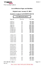
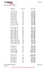
The list of effective pages in this manual corresponds to that of the basic

Pilot's Operating Handbook.

PIM - DO NOT USE FOR FLIGHT OPERATIONS

Summary of Contents for TBM 960

Page 1: ...ect to change without notice 2022 DAHER AEROSPACE All rights reserved DAHER AEROSPACE Customer Care 65921 TARBES CEDEX 9 FRANCE Printed in FRANCE TBM 960 Pilot s Information Manual P N DMMPIPYEE0EN Edition 0 Revision 2 CAUTION This information manual is a non official copy of the pilot s operating handbook and may be used for general information purposes only It is not kept current and therefore c...

Page 2: ...2 3 1 to 2 3 4 00 JAN 2022 2 4 1 to 2 4 1 00 JAN 2022 2 5 1 to 2 5 4 00 JAN 2022 2 6 1 to 2 6 16 00 JAN 2022 2 7 1 to 2 7 2 01 MAR 2022 2 8 1 to 2 8 5 00 JAN 2022 2 9 1 to 2 9 11 01 MAR 2022 3 A 1 to 3 A 3 02 APR 2022 3 0 1 to 3 0 3 02 APR 2022 3 1 1 to 3 1 4 00 JAN 2022 Section 0 Pilot s Operating Handbook POH TBM 960 Edition 0 Rev 02 Page 0 19 PIM DO NOT USE FOR FLIGHT OPERATIONS 0 1 to 0 1 02 0...

Page 3: ... 00 JAN 2022 3A 6 1 to 3A 2 1 00 JAN 2022 3A 7 1 to 3A 7 15 01 MAR 2022 3A 8 1 to 3A 8 5 00 JAN 2022 3A 9 1 to 3A 9 7 00 JAN 2022 3A 10 1 to 3A 10 5 00 JAN 2022 3A 11 1 to 3A 11 10 00 JAN 2022 3A 12 1 to 3A 12 22 00 JAN 2022 3A 13 1 to 3A 13 4 00 JAN 2022 4 0 1 to 4 0 3 02 APR 2022 4 1 1 to 4 1 1 00 JAN 2022 4 2 1 to 4 2 1 00 JAN 2022 4 3 1 to 4 3 23 01 MAR 2022 4 4 1 to 4 4 65 01 MAR 2022 4 5 1 t...

Page 4: ...5 01 MAR 2022 7 4 1 to 7 4 29 00 JAN 2022 7 5 1 to 7 5 16 01 MAR 2022 7 6 1 to 7 6 27 02 APR 2022 7 7 1 to 7 7 10 01 MAR 2022 7 8 1 to 7 8 15 00 JAN 2022 7 9 1 to 7 9 26 02 APR 2022 7 10 1 to 7 10 15 02 APR 2022 7 11 1 to 7 11 11 00 JAN 2022 7 12 1 to 7 12 5 00 JAN 2022 7 13 1 to 7 13 4 00 JAN 2022 7 14 1 to 7 14 5 00 JAN 2022 7 15 1 to 7 15 17 01 MAR 2022 8 0 1 to 8 0 2 02 APR 2022 8 1 1 to 8 1 1...

Page 5: ...Page No Rev No Rev Date 8 9 1 to 8 9 15 01 MAR 2022 8 10 1 to 8 10 2 00 JAN 2022 Section 0 Pilot s Operating Handbook POH TBM 960 Edition 0 Rev 02 Page 0 22 PIM DO NOT USE FOR FLIGHT OPERATIONS ...

Page 6: ...mergency Procedures 3 Abnormal Procedures 3A Normal Procedures 4 Performance 5 Weight and Balance 6 Description 7 Handling Servicing and Maintenance 8 Section 0 Pilot s Information Manual PIM TBM 960 Edition 0 Rev 02 PIM DO NOT USE FOR FLIGHT OPERATIONS ...

Page 7: ...nd Terminology 1 4 1 Meteorological Terminology 1 4 1 General Airspeed Terminology and Symbols 1 4 1 Power Terminology 1 4 2 Airplane Performance and Flight Planning Terminology 1 4 2 Weight and Balance Terminology 1 4 3 General Abbreviations 1 4 3 Radio Navigation Abbreviations 1 4 8 1 5 Conversion Factors 1 5 1 1 6 Pressure and Standard Atmosphere 1 6 1 Standard Atmosphere 1 6 1 Pressure Convers...

Page 8: ...Section 1 General Pilot s Information Manual Intentionally left blank PIM TBM 960 Edition 0 Rev 02 Page 1 0 2 PIM DO NOT USE FOR FLIGHT OPERATIONS ...

Page 9: ...n 9 Supplements The installed ADS B OUT system has been shown to meet the equipment requirements of 14 CFR 91 227 The installed transponder system is able to respond to interrogations in Modes A C and S and is fully compliant with the requirements of CS ACNS D ELS EHS Mode S Elementary Enhanced Surveillance The installed ADS B OUT system is fully compliant with the requirements of CS ACNS D ADSB 1...

Page 10: ...Section 1 General Pilot s Information Manual Intentionally left blank PIM TBM 960 Edition 0 Rev 00 Page 1 1 2 PIM DO NOT USE FOR FLIGHT OPERATIONS ...

Page 11: ... 71 ft mini 0 207 m 2 914 m 3 874 m 4 355 m 14 29 ft I4061000AAAHMA8000 10 736 m 35 22 ft Airplane on a level surface with fully extended FWD shock absorber Section 1 General Pilot s Information Manual PIM TBM 960 Edition 0 Rev 00 Page 1 2 1 PIM DO NOT USE FOR FLIGHT OPERATIONS ...

Page 12: ...re 1 2 2 Three View Drawing 2 2 I4061000AAAIMA8000 16 36 ft 4 988 m 12 833 m 42 1 ft Section 1 General Pilot s Information Manual PIM TBM 960 Edition 0 Rev 00 Page 1 2 2 PIM DO NOT USE FOR FLIGHT OPERATIONS ...

Page 13: ...Digital Engine Control FADEC system Propeller Number of propellers 1 Propeller manufacturer Hartzell Propeller model number 5D31 NK366B1 86DB01B Number of blades 5 Propeller diameter 91 in 2 311 m Propeller type Adjustable constant speed with feathering and hydraulic control reverse Propeller blade setting at 30 inch station Low pitch 19 5 Feathering 86 1 Maximum reverse 9 3 The electro hydro mech...

Page 14: ...ion UK NATO Code ASTM D1655 JET A ASTM D1655 JET A1 AIR 3405C Grade F35 DERD 2494 Issue 9 F35 MIL DTL 5624 Grade JP 5 AIR 3404C Grade F44 DERD 2452 Issue 2 Amendment 1 F44 MIL DTL 83133 Grade JP 8 AIR 3405C Grade F34 DERD 2453 Issue 4 Amendment 1 F34 AIR 3404C Grade F43 DERD 2498 Issue 7 F43 Already contains an anti ice additive Requires an anti ice additive Engine Oil System total capacity 12 7 q...

Page 15: ...sition see Figure 2 5 2 Baggage weight For weight and C G limits refer to Paragraph Weight Limits in Subsection 2 5 For cargo loading instructions refer to Subsection 6 3 Baggage Loading Standard Airplane Weights Standard empty weight 4 784 lbs 2 170 kg Maximum useful load 2 831 lbs 1 284 kg Cabin and Entry Dimensions Maximum cabin width 3 97 ft 1 21 m Maximum cabin length 13 29 ft 4 05 m Maximum ...

Page 16: ...ft 0 70 m Pilot entry mean height 3 18 ft 0 97 m Specific Loadings Wing loading 39 3 lbs ft2 191 9 kg m2 Power loading 8 5 lbs SHP 3 86 kg SHP Section 1 General Pilot s Information Manual PIM TBM 960 Edition 0 Rev 00 Page 1 3 4 PIM DO NOT USE FOR FLIGHT OPERATIONS ...

Page 17: ...cted for position and instrument error Knots calibrated airspeed is equal to KTAS in standard atmosphere at sea level KIAS Knots Indicated Airspeed the speed shown on the airspeed indicator and expressed in knots KTAS Knots True Airspeed the airspeed expressed in knots relative to undisturbed air which is KCAS corrected for altitude and temperature VA Maneuvering Speed the maximum speed at which f...

Page 18: ...nditions to maintain a specified power Hot start Engine start or attempt to start that causes the interturbine temperature to be higher than the maximum value permissible during start Flameout Involuntary loss of the combustion chamber flame during operation GPU Ground Power Unit Feathering Action which reduces the drag of a propeller by positioning blades at the pitch angle creating minimal drag ...

Page 19: ...point Its distance from the reference datum is found by dividing the total moment by the total weight of the airplane C G limits The extreme center of gravity locations within which the airplane must be operated at a given weight Standard empty weight Weight of a standard airplane including unusable fuel and full operating fluids oil and hydraulic fluids Basic empty weight Standard empty weight pl...

Page 20: ...ter of Gravity CONT Control cu ft Cubic Feet DCTU Data Collection and Transmission Unit DIEGME Diethylene Glycol Monomethyl Ether DISC Disconnect DN Down ECS Environmental Control System EDM Emergency Descent Mode EGME Ethylene Glycol Monomethyl Ether EIS Engine Indication System EMER Emergency ESP Electronic Stability Protection ESS BUS TIE Essential Bus Tie EXT LIGHTS External Lights F Degrees F...

Page 21: ...gh HP High Pressure hPa Hectopascal HTR Heater HTRS Heaters IAS Indicated Airspeed IGNIT Ignition in Inch Inches INDIC Indicator INERT SEP Inertial Separator in Hg Inches of Mercury in lbs Inch pounds INSTR Instrument INT LIGHTS Interior Lights ITT Interturbine Temperature kg Kilogram kg h Kilogram per Hour kg m2 Kilograms per Square Meter kg SHP Kilogram per Shaft Horsepower Section 1 General Pil...

Page 22: ...corder LFE Landing Field Elevation l h Liter per Hour L H Left Hand LO Low LP Low Pressure LRCR Long Range Cruise LRN Long Range Navigation LTS TEST Lights Test LVL Level m Meter M Mach Number MAC Mean Aerodynamic Chord MAIN GEN Main Generator MAN Manual MAX RPM Maximum Revolutions per Minute mb Millibar MFD Multifunction Display min Minute MIN Minimum m kg Kilogram meters Section 1 General Pilot ...

Page 23: ... psi Pounds per Square Inch PSIG Pounds per Square Inch Gauge qt Quart USG qt h Quart per Hour QTY Quantity R Right RCR Recommended Cruise R H Right Hand RUD Rudder s Second SEI Single Engine Indicator SEL Selector SIG Signalization SL Sea Level S N Serial Number SPKR Speaker STALL HTR Stall Warning Heater ST BY Standby Std Standard STPD Standard Temperature Pressure Dry Section 1 General Pilot s ...

Page 24: ...ronautical Information Regulation and Control AP Autopilot APR Approach ATC Air Traffic Control Baro VNAV Barometric Vertical NAVigation CDI Course Deviation Indicator COM Communications Transceivers DA Decision Altitude DH Decision Height DME Distance Measuring Equipment DR Dead Reckoning ELT Emergency Locator Transmitter FAF Final Approach Fix FD Flight Director FDE Fault Detection and Exclusion...

Page 25: ...F Legs Radius to Fix Legs RNAV Area NAVigation RNP Required Navigation Performance RVSM Reduced Vertical Separation Minimum SBAS Satellite Based Augmentation System STAR Standard Terminal Arrival Route TAS Traffic Advisory System TAWS Terrain Awareness Warning System VDI Vertical Deviation Indicator VFR Visual Flight Rules VHF Very High Frequency VMC Visual Meteorological Conditions VNAV Vertical ...

Page 26: ...Section 1 General Pilot s Information Manual Intentionally left blank PIM TBM 960 Edition 0 Rev 00 Page 1 4 10 PIM DO NOT USE FOR FLIGHT OPERATIONS ...

Page 27: ...units Multiply By To obtain Multiply By To obtain feet 0 3048 meters meters 3 2808 feet inches 25 4 mm mm 0 03937 inches Imp Gal 4 546 liters liters 0 220 Imp Gal USG 3 785 liters liters 0 264 USG lbs 0 45359 kg kg 2 2046 lbs Section 1 General Pilot s Information Manual PIM TBM 960 Edition 0 Rev 00 Page 1 5 1 PIM DO NOT USE FOR FLIGHT OPERATIONS ...

Page 28: ... to Meters feet meters 31 000 30 000 20 000 10 000 0 2 500 5 000 7 500 10 000 C4010000AAALMA8000 Section 1 General Pilot s Information Manual PIM TBM 960 Edition 0 Rev 00 Page 1 5 2 PIM DO NOT USE FOR FLIGHT OPERATIONS ...

Page 29: ... 1 5 2 Inches to Millimeters C4010000AAALMA8100 in 40 30 20 10 0 250 500 750 1 000 mm Section 1 General Pilot s Information Manual PIM TBM 960 Edition 0 Rev 00 Page 1 5 3 PIM DO NOT USE FOR FLIGHT OPERATIONS ...

Page 30: ...ounds to Kilograms C4010000AAALMA8200 lbs 8 000 6 000 4 000 2 000 0 kg 1 000 2 000 3 000 4 000 Section 1 General Pilot s Information Manual PIM TBM 960 Edition 0 Rev 00 Page 1 5 4 PIM DO NOT USE FOR FLIGHT OPERATIONS ...

Page 31: ...8 000 752 6 0 8 30 5 10 000 696 8 4 8 23 4 12 000 644 3 8 7 16 2 14 000 595 2 12 7 9 2 16 000 549 1 16 6 2 2 18 000 505 9 20 6 5 0 20 000 465 6 24 6 12 4 22 000 427 8 28 5 19 3 24 000 392 6 32 5 26 5 26 000 359 8 36 5 33 6 28 000 329 3 40 4 40 7 30 000 300 8 44 4 47 8 31 000 287 4 46 4 51 6 Section 1 General Pilot s Information Manual PIM TBM 960 Edition 0 Rev 00 Page 1 6 1 PIM DO NOT USE FOR FLIG...

Page 32: ...993 29 32 994 29 35 995 29 38 996 29 41 997 29 44 998 29 47 999 29 50 1 000 29 53 1 001 29 56 1 002 29 59 1 003 29 62 1 004 29 65 1 005 29 68 1 006 29 71 1 007 29 74 1 008 29 77 1 009 29 80 1 010 29 83 1 011 29 85 1 012 29 88 1 013 29 91 1 014 29 94 1 015 29 97 1 016 30 00 1 017 30 03 1 018 30 06 1 019 30 09 1 020 30 12 1 021 30 15 1 022 30 18 1 023 30 21 1 024 30 24 1 025 30 27 1 026 30 30 1 027 ...

Page 33: ...1 Flight Load Factor Limits 2 6 1 Generator Limits 2 6 2 GFC 700 Autopilot Limits 2 6 2 Autothrottle AT Limits 2 6 2 HomeSafe Emergency Function 2 6 2 GNSS GPS SBAS Navigation Equipment Approvals 2 6 3 GNSS GPS SBAS Navigation System Limitations 2 6 6 Icing Conditions 2 6 8 Severe Icing Conditions 2 6 9 Flap Operating Envelope 2 6 10 Reverse Utilization 2 6 10 Weather Radar 2 6 10 Equipment Requir...

Page 34: ...ge Limits 2 7 1 Minimum Crew 2 7 1 Maximum Occupancy 2 7 1 Use of Doors 2 7 1 Cargo Net Installation Limits 2 7 1 2 8 Markings 2 8 1 Airspeed Indicator on PFD s and on Standby Airspeed Indicator 2 8 1 Pressurization 2 8 1 Engine Instruments 2 8 2 2 9 Placards 2 9 1 Section 2 Limitations Pilot s Information Manual PIM TBM 960 Edition 0 Rev 02 Page 2 0 2 PIM DO NOT USE FOR FLIGHT OPERATIONS ...

Page 35: ...ry fails its initial capacity check with associated message WARNING INTERNAL BATTERY MAY PROVIDE LESS THAN 60 MINUTES OF OPERATION or if there is a red X over the battery symbol at MD302 initialization This section of the airplane POH presents the various operating limitations the significance of such limitations instrument markings color coding and basic placards necessary for the safe operation ...

Page 36: ...Section 2 Limitations Pilot s Information Manual Intentionally left blank PIM TBM 960 Edition 0 Rev 00 Page 2 1 2 PIM DO NOT USE FOR FLIGHT OPERATIONS ...

Page 37: ...this speed VFE Maximum flaps extended speed Do not exceed these speeds depending on flaps position Landing configuration 120 122 Takeoff configuration 180 178 VLO Maximum landing gear operating speed Do not extend or retract landing gear above this speed Extension 180 178 Retraction 151 150 Emergency extension 151 150 VLE Maximum landing gear extended speed 180 178 Do not exceed this speed with la...

Page 38: ...Pilot s Information Manual Section 2 Limitations Intentionally left blank PIM TBM 960 Edition 0 Rev 00 Page 2 2 2 PIM DO NOT USE FOR FLIGHT OPERATIONS ...

Page 39: ... continuous 850 C 850 C ITT 900 C acceptable for maximum 20 seconds NOTE During normal operation the power settings are defined by the FADEC to maintain ITT below 840 C During start 850 C 850 C ITT 900 C acceptable for maximum 20 seconds 900 C ITT 1 000 C acceptable for maximum 5 seconds Oil CAUTION Do not mix different viscosities or specifications of oil as their different chemical structure can...

Page 40: ...e as soon as possible using the minimum power required to sustain flight Oil capacity System total capacity 12 7 qt 12 liters oil cooler included Usable capacity 6 qt 5 7 liters Fuel Fuel limitations Two tanks 150 5 USG 570 liters each Total fuel 301 USG 1 140 liters Usable fuel 292 USG 1 106 liters Unusable fuel 9 USG 34 liters Maximum fuel imbalance 15 USG 57 liters NOTE The quantity of usable f...

Page 41: ...DERD 2453 Issue 4 Amendment 1 F34 AIR 3404C Grade F43 DERD 2498 Issue 7 F43 Already contains an anti ice additive Requires an anti ice additive Propeller Number of propellers 1 Propeller manufacturer Hartzell Propeller model number 5D31 NK366B1 86DB01B Propeller diameter 91 in 2 311 m Propeller blade setting at 30 inch station Low pitch 19 5 Feathering 86 1 Maximum reverse 9 3 Full Authority Digit...

Page 42: ...first appearance The full duration of the flight after which LMTD DISPATCH first appeared must be counted when calculating the 50 flight hour time period Calculating the 50 flight hour time period is the pilot s responsibility Pilot s Information Manual Section 2 Limitations PIM TBM 960 Edition 0 Rev 00 Page 2 3 4 PIM DO NOT USE FOR FLIGHT OPERATIONS ...

Page 43: ...ion The FADEC limits the use of starter to a total duration of 80 seconds including dry motoring and start sequences Should several start up sequences be necessary respect the following spacings between attempts Between 1st and 2nd sequence wait for 1 minute Between 2nd and 3rd sequence wait for 5 minutes Between 3rd and 4th sequence wait for 30 minutes Pilot s Information Manual Section 2 Limitat...

Page 44: ...Pilot s Information Manual Section 2 Limitations Intentionally left blank PIM TBM 960 Edition 0 Rev 00 Page 2 4 2 PIM DO NOT USE FOR FLIGHT OPERATIONS ...

Page 45: ... 7 The Maximum Takeoff Weight of 3 354 kg is valid only for C G at 23 8 The Maximum Takeoff Weight increases linearly from 3 354 kg to 3 454 kg between 23 8 and 34 4 of C G For example MTOW 3 394 kg for C G at 28 see Figure 2 5 2 Maximum baggage weight in the front baggage compartment non pressurized 110 lbs 50 kg With 6 seat accommodation in rear part of pressurized cabin 220 lbs 100 kg With 4 se...

Page 46: ...664 m aft of datum at 6 250 lbs 2 835 kg 18 of MAC 185 3 in 4 707 m aft of datum at 6 579 lbs 2 984 kg 20 85 of MAC 187 1 in 4 752 m aft of datum at 7 024 lbs 3 186 kg 23 8 of MAC 187 1 in 4 752 m aft of datum at 7 394 lbs 3 354 kg 23 8 of MAC 193 4 in 4 912 m aft of datum at 7 615 lbs 3 454 kg 34 4 of MAC Aft limits 193 6 in 4 916 m aft of datum at 7 615 lbs 3 454 kg 34 7 of MAC 193 7 in 4 921 m ...

Page 47: ...Subsection 6 1 General for proper loading instructions Figure 2 5 2 C G Limits C4080000AABAMA8000 Max Takeoff Weight MTOW Max Ramp Weight MRW 14 16 18 20 22 24 26 28 30 32 34 36 MAC 16 18 20 22 24 26 28 30 32 34 MAC 40 44 48 52 56 60 64 68 72 76 Airplane weight lbs x 100 18 20 25 30 35 Airplane weight kg x 100 Pilot s Information Manual Section 2 Limitations PIM TBM 960 Edition 0 Rev 00 Page 2 5 3...

Page 48: ...5 3 Example of C G Outside the Limits when Fuel on Board Decreases C4080000AABIMA8000 Max Ramp Weight MRW Max Takeoff Weight MTOW Max Landing Weight MLW Max Zero Fuel Weight MZFW Ramp Weight Takeoff Weight Zero Fuel Weight Empty Weight 14 16 18 20 22 24 26 28 30 32 34 36 MAC 16 18 20 22 24 26 28 30 32 34 MAC 17 20 25 30 35 Airplane weight kg x 100 Pilot s Information Manual Section 2 Limitations P...

Page 49: ...d Temperature Limits Minimum temperature at start and takeoff 40 C 40 F Maximum temperature at start and takeoff ISA 37 C 67 F from 0 to 8 000 ft pressure altitude Maximum temperature in flight ISA 37 C 67 F from 0 to 8 000 ft pressure altitude ISA 30 C 54 F above 8 000 ft pressure altitude Flight Load Factor Limits Flaps Up Weight below 6 579 lbs 2 984 kg 1 5 n 3 8 g Weight above 6 579 lbs 2 984 ...

Page 50: ...AT Limits Do not engage autothrottle for taxi Do not engage autothrottle below 1 000 ft 300 m AGL in case of takeoff without autothrottle Do not engage autothrottle during landing and touch and go Disengage autothrottle if speed is not controlled within 5 KIAS range Do not engage autothrottle when autopilot is coupled with the flight director on PFD2 XFR right For approaches the SPD source switch ...

Page 51: ... Class 3 approved Garmin GDUs Display Units Garmin GA36 and GA37 antennas GPS software version 7 0 or later approved version is installed in this airplane in accordance with AC 20 138A is as installed in this airplane approved for navigation using GPS and GPS SBAS within the coverage of a SBAS complying with ICAO Annex 10 for IFR enroute terminal area and RNP APCH operations to LNAV LNAV VNAV and ...

Page 52: ...l See Note 2 FAA AC 90 105A R L1 Additional communication and surveillance equipment may be required to obtain operational approval to utilize RNP 4 performance Departure En route continental Arrival RNAV 2 RNAV 1 One GNSS system required to be operational JAA TGL 10 FAA AC 90 105A R C2 D2 Domestic Offshore Oceanic and Remote continental RNP 2 GNSS FDE availability must be verified prior to oceani...

Page 53: ...ures containing RF Legs QNH shall be available at the destination airport when conducting a Baro VNAV approach Use of remote altimeter setting source is not allowed to conduct a Baro VNAV approach The two primary altimeters must be operational when flying a RNP APCH LNAV VNAV with Baro VNAV guidance EASA AMC 20 27 FAA AC 90 105A R S2 Includes area navigation approaches titled RNAV GPS and RNAV GNS...

Page 54: ...quality and database management processes for many of its aviation databases LOA status and RTCA DO 200A List of Applicable Avionics 190 01999 00 can be viewed at FlyGarmin com Navigation information is referenced to WGS 84 reference system and should only be used where the Aeronautical Information Publication including electronic data and aeronautical charts conform to WGS 84 or equivalent GNSS G...

Page 55: ...d Obstacle Departure Procedures ODPs Standard Terminal Arrival STAR and enroute RNAV Q and RNAV T routes should be loaded into the flight plan from the database in their entirety rather than loading route waypoints from the database into the flight plan individually Selecting and inserting individual named fixes from the database is permitted provided all fixes along the published route to be flow...

Page 56: ...nd utilized when conducting procedures containing RF Legs Advisory visual approaches WARNING Use of advisory visual approaches in IMC is prohibited Advisory visual approaches are intended to be used as an aid to situational awareness and do not guarantee terrain or obstruction clearance along the approach path Icing Conditions Except for certain phases of flight where the POH specifies that deicin...

Page 57: ... severe icing conditions that exceed those for which the airplane is certificated shall be determined by the following visual cues If one or more of these visual cues exists immediately request priority handling from air traffic control to facilitate a route or an altitude change to exit the icing conditions Unusually extensive ice accumulation on the airframe and windshield in areas not normally ...

Page 58: ...anned by antenna when system is transmitting CAUTION The weather radar can be displayed on PFD 1 PFD 2 and MFD with different indications of mode The radar is in standby mode only when all displays indicate STANDBY Equipment Required Depending on Type of Operation The airplane is approved for day night VFR and day night IFR operations when appropriate equipment is installed and operating correctly...

Page 59: ...ference instrument 2 CAS warning and caution messages FADEC monitoring Oil pressure Low fuel pressure Fuel selector OFF Fuel auxiliary pump ON Left and right fuel tank low level Non functioning of fuel timer Battery stop Main generator OFF Low voltage Ground power unit connected Inertial separator Starter Ignition Flaps Landing gears and doors 3 Aural warning VMO warning Landing gear warning Stall...

Page 60: ...arter generator Inertial separator Stall warning Electrical aileron trim Electrical rudder trim Manual elevator pitch trim Engine ignition Landing gear electro hydraulic unit Landing gear emergency hydraulic pump manual Flaps Electrical feathering Battery 7 Miscellaneous Seats each occupant Belts each occupant Straps each occupant Pilot s Operating Handbook Night VFR 1 All equipment required for d...

Page 61: ...ed flight 1 Cabin altimeter 2 Cabin vertical speed indication 3 Cabin differential pressure indication 4 Pressurization control valve 5 Safety valve 6 Pressurization control 7 Maximum cabin altitude and pressure warning light Flight into icing conditions 1 All equipment required for IFR flight 2 Propeller deicing 3 Left windshield deicing 4 Airframe stabilizer and elevator horn deicing 5 Wing lead...

Page 62: ...ment listed hereafter or later approved versions must be installed and operating normally upon entering RVSM airspace Equipment Installed quantity Required quantity Barometric altimeter Air Data Computer 2 2 Avionics Display Unit 3 2 Autopilot altitude hold function AFCS mode controller 1 1 Integrated Avionics Computer 2 2 AHRS 2 2 ATC transponder with ADS B OUT function 1 or 2 1 NOTE Any changes ...

Page 63: ... european airspace The capability to transmit data parameters is shown in column 2 Parameter Available A Not available NA Magnetic heading A Indicated airspeed A Mach No A Vertical rate A Roll angle A True airspeed A True track angle A Ground speed A Selected altitude A Barometric pressure setting A Chartview System Operating Limitations The geographic referenced airplane symbol on some charts mus...

Page 64: ... during low visibility taxi operations Position accuracy orientation and related guidance must be assured by other means of required navigation Operators must have backup charts available to the flight crew Database currency must be verified prior to use via database effectivity page The flight crew is responsible for verifying availability of charts for the planned flight Pilot s Information Manu...

Page 65: ...e in pressurized cabin at 303 in 7 695 m Baggage in non pressurized forward compartment at 128 in 3 250 m Minimum Crew One pilot at left front seat Maximum Occupancy The number of persons on board is limited by approved seating configuration installed but must not exceed six including the pilot The number of persons must be less than or equal to the number of seats Use of Doors Flight with an open...

Page 66: ...in cabin out of baggage compartment CAUTION No item may extend forward of the cargo net system to protect door from obstruction Pilot s Information Manual Section 2 Limitations PIM TBM 960 Edition 0 Rev 01 Page 2 7 2 PIM DO NOT USE FOR FLIGHT OPERATIONS ...

Page 67: ...5 KIAS is maximum weight VS0 in landing configuration Thin white strip 81 122 Thin green strip 81 122 Normal operating airspeed range 81 KIAS is maximum weight VS1 with landing gear and flaps UP Thick green strip 122 266 Red white barber pole strip Above 266 266 KIAS VMO Pressurization Table 2 8 2 Pressurization Marking Marking Value Significance Red line 6 2 psi Cabin differential pressure limit ...

Page 68: ... 832 F ITT Engine running 850 to 900 C 1 562 to 1 652 F 400 to 850 C 752 to 1 562 F 900 C 1 652 F Torque TRQ 103 to 118 0 to Max available 118 Limit for 20 seconds maximum between 850 C and 900 C The FADEC continuously sends to the avionics the maximum TRQ available that depends on current airplane operation and current external conditions The upper boundary of the green arc is updated accordingly...

Page 69: ...and Ng 72 None Yellow 104 C 110 10 minutes 40 C None Red 104 C 110 10 minutes 110 C None Table 2 8 5 Oil Pressure Digit Colors Range psi Time condition Digit color 60 psi 100 and Ng 72 None Green 60 psi 100 and Ng 72 5 seconds 100 psi 135 None 40 psi 60 20 seconds Yellow 60 psi 100 and Ng 72 5 seconds 135 psi 175 20 seconds 40 psi None Red Continue Pilot s Information Manual Section 2 Limitations ...

Page 70: ...n Digit color 50 7 Ng 104 None Green 104 Ng 104 3 20 seconds Yellow 104 20 seconds Red 104 3 None Table 2 8 7 Propeller RPM Np Digit Colors Range RPM Time condition Digit color 1 905 None White 1 955 Np 2 030 None 1 905 Np 1 955 None Green 2 030 Np 2 100 None Yellow 2 030 20 seconds Red 2 100 None Pilot s Information Manual Section 2 Limitations PIM TBM 960 Edition 0 Rev 00 Page 2 8 4 PIM DO NOT U...

Page 71: ...Engine running Digit Colors Range C Time condition Digit color 850 C None Green 850 C 900 20 seconds Yellow 850 C 20 seconds Red 900 C None Table 2 8 10 Torque Digit Colors Range Time condition Digit color 103 None Green 103 TRQ 118 5 seconds 103 TRQ 118 5 seconds Yellow 103 20 seconds Red 118 None Pilot s Information Manual Section 2 Limitations PIM TBM 960 Edition 0 Rev 00 Page 2 8 5 PIM DO NOT ...

Page 72: ...Pilot s Information Manual Section 2 Limitations Intentionally left blank PIM TBM 960 Edition 0 Rev 00 Page 2 8 6 PIM DO NOT USE FOR FLIGHT OPERATIONS ...

Page 73: ...g 7615 lbs 3225 kg 7110 lbs FLAPS UP WEIGHT BELOW 2984 kg 6579 lbs ABOVE 2984 kg 6579 lbs 1 5 n 3 8 g 1 5 n 3 5 g 150 KIAS 178 KIAS 34 4 34 7 3354 kg 7394 lbs 23 8 MTOW MLW 3225 kg 7110 lbs 2 On the pressurized baggage compartment partition wall I4113500AAABMA18001 100 kg 220 lbs MAXIMUM IT IS THE PILOT S RESPONSIBILITY TO CHECK THAT ALL THE BAGGAGE IS PROPERLY SECURED FOR LOADING INSTRUCTIONS SEE...

Page 74: ...4113500AAAAMA18100 5 On the forward baggage compartment door frame non pressurized I4112001AAAFMA8000 IN PILOT S OPERATING HANDBOOK 50 kg 110 Ibs MAXIMUM FOR LOADING INSTRUCTIONS SEE WEIGHT AND BALANCE DATA 6 On the pedestal console C4113006AAAAMA8300 NOSE DOWN NOSE AILERON TRIM L R UP GND FEATHER MAX IDLE REV MAX IDLE REV FLAPS LDG TO UP 7 On the fuel selector Section 2 Limitations Pilot s Inform...

Page 75: ...TING HANDBOOK FOR OTHER APPROVED FUELS QUANTITY AND TYPE OF ADDITIVE TOTAL CAPACITY 150 5 us gal 570 l I4112004AAAAMA8200 9 On internal face of left side engine cowling 10 On the landing gear emergency control access door Section 2 Limitations Pilot s Information Manual PIM TBM 960 Edition 0 Rev 01 Page 2 9 3 PIM DO NOT USE FOR FLIGHT OPERATIONS ...

Page 76: ...ove the passenger s table I4113400AAADMA8300 TABLE MUST BE STOWED DURING TAKE OFF AND LANDING 13 Under the right control wheel 14 On the nose gear door Section 2 Limitations Pilot s Information Manual PIM TBM 960 Edition 0 Rev 01 Page 2 9 4 PIM DO NOT USE FOR FLIGHT OPERATIONS ...

Page 77: ...MAIN LANDING GEAR TIRE PRESSURE 8 96 bar 130 psi C4112001AABAMA8200 17 On the engine cowling in front of the compartment door C4112001AABAMA8100 EXTERNAL POWER 28 VOLTS D C NOMINAL 800 AMPS STARTING CAPACITY MIN DO NOT EXCEED 1000 AMPS 18 On the pilot door External side if installed Section 2 Limitations Pilot s Information Manual PIM TBM 960 Edition 0 Rev 01 Page 2 9 5 PIM DO NOT USE FOR FLIGHT O...

Page 78: ...n the access door External side I4112002AAAEMA8000 T U R N T O O P E N 20 On the outer fuselage skin aft of the access door Section 2 Limitations Pilot s Information Manual PIM TBM 960 Edition 0 Rev 01 Page 2 9 6 PIM DO NOT USE FOR FLIGHT OPERATIONS ...

Page 79: ...nternal side C4113400AAAGMA8000 HOLD TO UNLOCK PULL T U R N 23 On the pilot door Internal side if installed 24 On the emergency exit handle Marking on cover and marking on handle Section 2 Limitations Pilot s Information Manual PIM TBM 960 Edition 0 Rev 01 Page 2 9 7 PIM DO NOT USE FOR FLIGHT OPERATIONS ...

Page 80: ...25 Above the emergency exit door 26 On the last step of stairs Section 2 Limitations Pilot s Information Manual PIM TBM 960 Edition 0 Rev 01 Page 2 9 8 PIM DO NOT USE FOR FLIGHT OPERATIONS ...

Page 81: ...RATURE F C 0 10 20 30 40 50 60 70 80 90 100 110 120 130 140 1150 1250 1350 1450 1550 1650 1750 1850 1950 2050 2150 2250 60 54 4 48 9 43 3 37 8 32 2 26 7 21 1 15 6 10 4 4 10 20 30 40 50 60 70 1 1 6 7 12 2 17 8 23 3 28 9 34 4 40 45 6 51 1 56 7 I4112400AAAAMA8000 29 On the oxygen service door Section 2 Limitations Pilot s Information Manual PIM TBM 960 Edition 0 Rev 01 Page 2 9 9 PIM DO NOT USE FOR F...

Page 82: ...t and headset hanger C4113200AAACMA8000 M A X W EIGHT CAPACITY 1 6kg 3 5 l b s 32 Above the AFCS control unit C4113207AAAAMA8000 HOMESAFE RESTRICTED TO SITUATIONS PILOT INCAPACITATION OF FUNCTION USE OF Section 2 Limitations Pilot s Information Manual PIM TBM 960 Edition 0 Rev 01 Page 2 9 10 PIM DO NOT USE FOR FLIGHT OPERATIONS ...

Page 83: ...oth sides of each buckle positioner SEAT BUCKLE POSITIONER ONLY C4112200AAABMA8000 Section 2 Limitations Pilot s Information Manual PIM TBM 960 Edition 0 Rev 01 Page 2 9 11 PIM DO NOT USE FOR FLIGHT OPERATIONS ...

Page 84: ...Section 2 Limitations Pilot s Information Manual Intentionally left blank PIM TBM 960 Edition 0 Rev 01 Page 2 9 12 PIM DO NOT USE FOR FLIGHT OPERATIONS ...

Page 85: ...P 3A 9 1 BAT OFF 3A 9 2 CABIN ALTITUDE and USE OXYGEN MASK 3 10 3 CABIN DIFF PRESS 3 10 5 CARGO DOOR 3A 13 1 CHIP 3A 3 2 DOOR 3 10 7 ECS DEGRADED 3A 10 1 EDM 3 10 4 ENG OP DEGRADED 3A 3 6 ENG PROT ACTIVE 3A 3 3 ESP DEGRADED AOA 3A 12 3 ESP DEGRADED IAS 3A 12 2 ESP FAIL 3A 12 1 EXCEEDANCE 3A 12 22 Section 3 Emergency Procedures Pilot s Information Manual PIM TBM 960 Edition 0 Rev 02 Page 3 A 1 PIM ...

Page 86: ...ST 3 12 8 HS ABN BRAKES 3A 7 15 HS CONFIG MODE 3 12 11 ICE DETECTED 3A 11 9 ICE DETECTION FAIL 3A 11 10 IGNITION 3A 13 3 INERT SEP FAIL 3A 11 3 ITT 3 3 13 ITT HI 3A 3 1 LDG GEAR UP 3A 7 1 LMTD DISPATCH 3A 13 4 LOW LVL FAIL L R 3A 8 4 LOW VOLTAGE 3A 9 4 MAIN GEN 3A 9 3 MAIN GEN and LOW VOLTAGE 3A 9 5 NG 3 3 15 Section 3 Emergency Procedures Pilot s Information Manual PIM TBM 960 Edition 0 Rev 02 Pa...

Page 87: ...L 3A 11 2 SET PWR TO IDLE 3A 3 5 STALL NO HEAT 3A 11 8 TCAS FAIL 3A 12 20 THROTTLE FAIL and FADEC FAIL 3 3 8 TRAFFIC FAIL 3A 12 21 USP ACTIVE 3 12 4 VACUUM LOW 3A 10 4 XPDR1 ADS B FAIL and XPDR2 ADS B FAIL 3A 12 18 XPDR1 FAIL and XPDR2 FAIL 3A 12 17 Section 3 Emergency Procedures Pilot s Information Manual PIM TBM 960 Edition 0 Rev 02 Page 3 A 3 PIM DO NOT USE FOR FLIGHT OPERATIONS ...

Page 88: ...Section 3 Emergency Procedures Pilot s Information Manual Intentionally left blank PIM TBM 960 Edition 0 Rev 02 Page 3 A 4 PIM DO NOT USE FOR FLIGHT OPERATIONS ...

Page 89: ...ulation Discrepancy THROTTLE FAIL or FADEC FAIL without Engine Shutdown 3 3 8 PROP 3 3 12 ITT 3 3 13 NG 3 3 15 OIL TEMP or OIL TEMP 3 3 16 FEATHER 3 3 18 3 4 Air Start 3 4 1 Air Start Envelope 3 4 1 Air Start Procedure 3 4 2 3 5 Fire and Smoke 3 5 1 Engine Fire on Ground 3 5 1 Cabin Fire on Ground 3 5 2 Engine Fire in Flight 3 5 3 Cabin Electrical Fire or Smoke During Flight 3 5 4 Smoke Eliminatio...

Page 90: ...E OXYGEN MASK 3 10 3 EDM 3 10 4 CABIN DIFF PRESS 3 10 5 O2 CYL CLOSED 3 10 6 DOOR 3 10 7 3 11 Deicing System 3 11 1 No Emergency Procedures 3 11 1 3 12 Avionics Miscellaneous 3 12 1 Unsuccessful AT Disconnection 3 12 1 Trim Runaway 3 12 2 USP ACTIVE 3 12 4 AURAL WRN FAIL 3 12 5 AURAL WRN 1 CHL 3 12 6 ABORT APR 3 12 7 HOMESAFE RQST 3 12 8 HomeSafe Deactivation 3 12 9 HS CONFIG MODE 3 12 11 3 13 Mis...

Page 91: ... 3 13 4 AP Off Stall Warning 3 13 5 Oxygen Use 3 13 6 Flight into Severe Icing Conditions 3 13 9 NO DISPATCH 3 13 10 Section 3 Emergency Procedures Pilot s Information Manual PIM TBM 960 Edition 0 Rev 02 Page 3 0 3 PIM DO NOT USE FOR FLIGHT OPERATIONS ...

Page 92: ...Section 3 Emergency Procedures Pilot s Information Manual Intentionally left blank PIM TBM 960 Edition 0 Rev 02 Page 3 0 4 PIM DO NOT USE FOR FLIGHT OPERATIONS ...

Page 93: ... or caution messages appearing in the CAS window The color code philosophy for CAS messages is the following the RED warning messages indicate a failure or a condition that requires an immediate action from the pilot the AMBER caution messages indicate a failure or a condition that requires an action from the pilot as soon as practicable and the WHITE advisory messages indicate a state of a system...

Page 94: ...ed to the WHITE advisory messages are described in the Garmin Pilot s Guide Procedure Format PROCEDURE TITLES Name of the procedure 1 X Procedure introduction or description of symptoms associated with the failure are presented like this at the beginning of the procedure 1 X is written if the procedure extends over two pages or more MEMORY ITEMS The memory items are indicated in bold font as shown...

Page 95: ...of a condition is indicated by End of procedure Continuation of a procedure on several pages is indicated by Continue at the bottom of the page Continuing at the top of the page FLY THE AIRPLANE DIRECTIVE Fly the airplane stands for a reminder of a basic flying rule Despite the critical situation keep focusing on control of the airplane while performing the necessary procedure LANDING DIRECTIVES L...

Page 96: ...dvisory CAS message ANNUNCIATIONS ON PFDs or MFD Indicated as displayed in the PFD or MFD with specifying annunciation next to the message BOTH ON AHRS1 annunciation HDG annunciation Pilot s Information Manual Section 3 Emergency Procedures PIM TBM 960 Edition 0 Rev 00 Page 3 1 4 PIM DO NOT USE FOR FLIGHT OPERATIONS ...

Page 97: ...runway 3 ENGINE MODE switch OFF 4 FUEL TANK SELECTOR OFF 5 Crash lever Pull down If necessary 6 Evacuate the airplane after coming to complete stop Do not unfasten seat belts before complete stop End of procedure Pilot s Information Manual Section 3 Emergency Procedures PIM TBM 960 Edition 0 Rev 00 Page 3 2 1 PIM DO NOT USE FOR FLIGHT OPERATIONS ...

Page 98: ...nway 4 ENGINE MODE switch OFF 5 FUEL TANK SELECTOR OFF 6 Crash lever Pull down If necessary 7 Evacuate the airplane after coming to complete stop Do not unfasten seat belts before complete stop End of procedure Pilot s Information Manual Section 3 Emergency Procedures PIM TBM 960 Edition 0 Rev 00 Page 3 2 2 PIM DO NOT USE FOR FLIGHT OPERATIONS ...

Page 99: ...Rotation 1 1 1 Perform procedure Engine Failure at Takeoff Before Rotation in Subsection 3 2 End of procedure Pilot s Information Manual Section 3 Emergency Procedures PIM TBM 960 Edition 0 Rev 00 Page 3 3 1 PIM DO NOT USE FOR FLIGHT OPERATIONS ...

Page 100: ...ain above 100 KIAS 3 THROTTLE IDLE 4 ENGINE MODE switch OFF 5 FUEL TANK SELECTOR OFF Before touchdown 6 FLAPS lever LDG 7 Crash lever Pull down 8 Evacuate the airplane after coming to complete stop Do not unfasten seat belts before complete stop End of procedure Continue Pilot s Information Manual Section 3 Emergency Procedures PIM TBM 960 Edition 0 Rev 00 Page 3 3 2 PIM DO NOT USE FOR FLIGHT OPER...

Page 101: ...100 KIAS 178 Flaps LDG 85 KIAS 122 11 THROTTLE IDLE 12 ENGINE MODE switch OFF 13 FUEL TANK SELECTOR OFF Before touchdown 14 Crash lever Pull down 15 Evacuate the airplane after coming to complete stop Do not unfasten seat belts before complete stop End of procedure Pilot s Information Manual Section 3 Emergency Procedures PIM TBM 960 Edition 0 Rev 00 Page 3 3 3 PIM DO NOT USE FOR FLIGHT OPERATIONS...

Page 102: ...DEC CH A FADEC CH B breakers Pull 6 FADEC CH A FADEC CH B breakers Push Figure 3 3 1 Location of FADEC Breakers C4255004AAAEMA8000 CH A FADEC BUS 1 BUS 2 BUS 3 ESS BUS 2 ESS BUS 1 BATT BUS PROP DE ICE ICE LIGHT ICE DETEC PWR2 COND CPCS AIR MFD CABIN A C COMP FLAPS SIG WXR TAS LDG CONT BU S 2 SATCOM SATCOM HEATER PANEL LIGHT NAV RECOG LIGHT DATA LINK CH B FADEC DOORS CABIN CH A FADEC GPS NAV 1 COM ...

Page 103: ...ion 3 4 End of procedure If FADEC FAIL is still ON or air start is not possible 9 Perform procedure Maximum Range Descent in Subsection 3 6 NOTE If FADEC FAIL is ON NO DISPATCH will be displayed when on ground refer to procedure NO DISPATCH in Subsection 3 13 End of procedure Pilot s Information Manual Section 3 Emergency Procedures PIM TBM 960 Edition 0 Rev 00 Page 3 3 5 PIM DO NOT USE FOR FLIGHT...

Page 104: ... for less than 20 seconds for low pressure below 60 PSI for less than 20 seconds or below 100 PSI for more than 5 seconds when Ng 72 NOTE OIL PRESS and OIL PRESS are inhibited during engine start sequence Fly the airplane Land as soon as possible 1 Oil pressure Monitor 2 THROTTLE Minimum power necessary for level flight at 120 KIAS CAUTION ENG OP DEGRADED may appear refer to procedure ENG OP DEGRA...

Page 105: ...r to procedure Oxygen Use in Subsection 3 13 4 THROTTLE IDLE 5 ENGINE MODE switch OFF 6 FUEL TANK SELECTOR OFF 7 Perform procedure Maximum Range Descent in Subsection 3 6 End of procedure Pilot s Information Manual Section 3 Emergency Procedures PIM TBM 960 Edition 0 Rev 00 Page 3 3 7 PIM DO NOT USE FOR FLIGHT OPERATIONS ...

Page 106: ...t valid throttle position 1 AT Disconnect In case engine regulation is back to normal Do not engage AT Land as soon as practicable Inform maintenance department Repair before further flight End of procedure If engine power allows for level flight at 120 KIAS or above CAUTION Avoid rapid THROTTLE movements No faster than 10 seconds between IDLE and maximum power positions Continue Pilot s Informati...

Page 107: ...l approach 5 FLAPS lever LDG Only on short final Do not perform a go around When runway is assured 6 THROTTLE IDLE 7 ENGINE MODE switch OFF 8 FUEL TANK SELECTOR OFF 9 Land normally 10 Brakes As required Inform maintenance department Repair before further flight NOTE If THROTTLE FAIL or FADEC FAIL are displayed in flight NO DISPATCH will be displayed when on ground refer to procedure NO DISPATCH in...

Page 108: ...Descent in Subsection 3 6 NOTE If THROTTLE FAIL or FADEC FAIL are displayed in flight NO DISPATCH will be displayed when on ground refer to procedure NO DISPATCH in Subsection 3 13 End of procedure If power is excessive to maintain level flight below 178 KIAS 16 Prepare for landing as soon as possible When approaching appropriate chosen airfield 17 Airspeed Reduce below 178 KIAS By setting nose up...

Page 109: ... TANK SELECTOR OFF 26 FLAPS lever LDG as required At IAS 122 KIAS 27 Land normally 28 Brakes As required Inform maintenance department Repair before further flight NOTE If THROTTLE FAIL or FADEC FAIL are displayed in flight NO DISPATCH will be displayed when on ground refer to procedure NO DISPATCH in Subsection 3 13 End of procedure Pilot s Information Manual Section 3 Emergency Procedures PIM TB...

Page 110: ...oid propeller rotation speeds higher than 2 030 RPM Land as soon as possible Do not perform a go around NOTE In that case the go around may damage the gear reduction box and the reverse efficiency might be lower than expected Inform maintenance department Repair before further flight End of procedure Pilot s Information Manual Section 3 Emergency Procedures PIM TBM 960 Edition 0 Rev 00 Page 3 3 12...

Page 111: ...ntrol the engine ITT parameter within the limitations During engine start NOTE During engine start if ITT is above 945 C the FADEC automatically aborts start sequence 1 Starting procedure Abort Refer to procedure Engine Start in Subsection 4 4 2 Cancel the flight Inform maintenance department End of procedure After engine start On ground 3 Cancel the flight Inform maintenance department End of pro...

Page 112: ...nnect 5 THROTTLE Reduce To get ITT in green sector Land as soon as possible Inform maintenance department End of procedure Pilot s Information Manual Section 3 Emergency Procedures PIM TBM 960 Edition 0 Rev 00 Page 3 3 14 PIM DO NOT USE FOR FLIGHT OPERATIONS ...

Page 113: ...seconds 1 AT Disconnect 2 THROTTLE Reduce To get Ng below 104 Land as soon as possible Inform maintenance department End of procedure Pilot s Information Manual Section 3 Emergency Procedures PIM TBM 960 Edition 0 Rev 00 Page 3 3 15 PIM DO NOT USE FOR FLIGHT OPERATIONS ...

Page 114: ...L PRESS or OIL PRESS displayed Fly the airplane 1 THROTTLE Minimum power necessary for level flight at 120 KIAS Land as soon as possible CAUTION ENG OP DEGRADED may appear refer to procedure ENG OP DEGRADED in Subsection 3A 3 Prepare for an engine stop shortly If engine power decreases If airplane altitude is 10 000 ft 2 Oxygen masks Use Refer to procedure Oxygen Use in Subsection 3 13 3 THROTTLE ...

Page 115: ...5 FUEL TANK SELECTOR OFF 6 Perform procedure Maximum Range Descent in Subsection 3 6 End of procedure Pilot s Information Manual Section 3 Emergency Procedures PIM TBM 960 Edition 0 Rev 00 Page 3 3 17 PIM DO NOT USE FOR FLIGHT OPERATIONS ...

Page 116: ...in and to provide electrical power from main generator 2 FLAPS and LANDING GEAR levers UP 3 Airspeed 120 KIAS 4 Prepare for a forced landing Refer to procedure Forced Landing or Ditching in Subsection 3 7 NOTE NO DISPATCH will be displayed when on ground refer to procedure NO DISPATCH in Subsection 3 13 End of procedure Pilot s Information Manual Section 3 Emergency Procedures PIM TBM 960 Edition ...

Page 117: ...titude ft Air Start Envelope NOTE Air start may be attempted outside of the envelope However above 20 000 ft or at lower speeds ITT tends to increase during start and prudence is recommended End of procedure Pilot s Information Manual Section 3 Emergency Procedures PIM TBM 960 Edition 0 Rev 00 Page 3 4 1 PIM DO NOT USE FOR FLIGHT OPERATIONS ...

Page 118: ... set to AUTO may cause overtemperature or abnormal acceleration 5 BLEED switch OFF RST 6 FAN selector OFF 7 Electric consumption Reduce 8 FUEL TANK SELECTOR L or R 9 THROTTLE IDLE 10 ENGINE MODE switch OFF then RUN Guarded 11 AUX BP switch AUTO 12 AUX BP ON Check ON 13 STARTER switch ON 2 seconds then release 14 STARTER Check ON 15 IGNITION Check ON Continue Pilot s Information Manual Section 3 Em...

Page 119: ... not successful 17 Perform procedure Maximum Range Descent in Subsection 3 6 End of procedure If air start is successful When Ng above 45 18 Starter Check OFF automatically 19 STARTER Check OFF 20 Engine parameters Check Oil pressure oil temperature and ITT in green sector 21 THROTTLE As required 22 TRQ available Check 23 BLEED switch As required 24 Electrical equipment As required Land as soon as...

Page 120: ...Pilot s Information Manual Section 3 Emergency Procedures Intentionally left blank PIM TBM 960 Edition 0 Rev 00 Page 3 4 4 PIM DO NOT USE FOR FLIGHT OPERATIONS ...

Page 121: ...ch OFF 3 FUEL TANK SELECTOR OFF 4 BLEED switch OFF RST 5 FAN selector OFF 6 Brakes As required If necessary 7 Warn ground assistance 8 Crash lever Pull down Evacuate as soon as possible End of procedure Pilot s Information Manual Section 3 Emergency Procedures PIM TBM 960 Edition 0 Rev 00 Page 3 5 1 PIM DO NOT USE FOR FLIGHT OPERATIONS ...

Page 122: ...akes As required If necessary 5 Warn ground assistance 6 Crash lever Pull down 7 Cabin fire extinguisher As required Evacuate as soon as possible End of procedure Pilot s Information Manual Section 3 Emergency Procedures PIM TBM 960 Edition 0 Rev 00 Page 3 5 2 PIM DO NOT USE FOR FLIGHT OPERATIONS ...

Page 123: ...OR OFF 5 AUX BP switch OFF 6 BLEED switch OFF RST 7 FAN selector OFF WARNING No air start attempt after an engine fire If necessary 8 Perform an emergency descent Refer to procedure Maximum Rate Descent in Subsection 3 6 9 Perform a forced landing Refer to procedure Forced Landing or Ditching in Subsection 3 7 End of procedure Pilot s Information Manual Section 3 Emergency Procedures PIM TBM 960 E...

Page 124: ...on If smoke or fire persists 7 Fly using the standby instrument 8 SOURCE selector OFF 9 GENERATOR selector OFF 10 Cabin fire extinguisher Use 11 All circuit breakers Pull Except FADEC CH A on ESS BUS 1 and FADEC CH B on BUS 2 12 All electrical equipment OFF NOTE Check for possible fire or smoke while re engaging necessary electrical equipment one after the other 13 SOURCE selector BATT 14 GENERATO...

Page 125: ...ve equipment breaker Pull 18 Not affected electrical equipment ON As required 19 Perform an emergency descent Refer to procedure Maximum Rate Descent in Subsection 3 6 Land as soon as possible End of procedure Pilot s Information Manual Section 3 Emergency Procedures PIM TBM 960 Edition 0 Rev 00 Page 3 5 5 PIM DO NOT USE FOR FLIGHT OPERATIONS ...

Page 126: ...til the cabin differential pressure drops 6 EMERGENCY RAM AIR control knob Pull If smoke decreases Land as soon as possible End of procedure If smoke increases 7 EMERGENCY RAM AIR control knob Push Land as soon as possible End of procedure Pilot s Information Manual Section 3 Emergency Procedures PIM TBM 960 Edition 0 Rev 00 Page 3 5 6 PIM DO NOT USE FOR FLIGHT OPERATIONS ...

Page 127: ...00 25 000 MO V 70 60 50 0 30 40 10 20 Altitude feet C4010000AAAGMA8000 Ground distances Nautical Miles Max Rate Descent Max Range Descent No wind Smooth atmosphere IAS 120 KIAS End of procedure Pilot s Information Manual Section 3 Emergency Procedures PIM TBM 960 Edition 0 Rev 00 Page 3 6 1 PIM DO NOT USE FOR FLIGHT OPERATIONS ...

Page 128: ...smooth air 4 FLAPS lever UP 5 LANDING GEAR lever UP 6 Airspeed VMO 266 KIAS If rough air or in case of structure problem 7 Airspeed Below 178 KIAS 8 FLAPS lever UP 9 LANDING GEAR lever DN End of procedure Pilot s Information Manual Section 3 Emergency Procedures PIM TBM 960 Edition 0 Rev 00 Page 3 6 2 PIM DO NOT USE FOR FLIGHT OPERATIONS ...

Page 129: ...bsection 3 13 2 THROTTLE IDLE 3 ENGINE MODE switch OFF 4 FUEL TANK SELECTOR OFF 5 FLAPS lever UP 6 LANDING GEAR lever UP 7 Airspeed 120 KIAS 8 DUMP switch Press 9 EMERGENCY RAM AIR control knob Pull If VMC and non icing conditions are possible 10 ESS BUS TIE switch EMER 11 Prepare for a forced landing Refer to procedure Forced Landing or Ditching in Subsection 3 7 End of procedure Continue Pilot s...

Page 130: ... R STALL HTR Check ON 19 Airspeed Above 135 KIAS Configuration flaps UP 20 AUX BP OFF 21 FUEL SEL MAN Status light in green 22 Lights All OFF 23 BLEED OFF RST 24 FAN OFF 25 AP TRIMS OFF 26 CABIN ACCESS OFF 27 All personal electrical devices Disconnect 28 Prepare for a forced landing Refer to procedure Forced Landing or Ditching in Subsection 3 7 End of procedure Pilot s Information Manual Section ...

Page 131: ... approach 9 ESS BUS TIE switch NORM To have GEAR and FLAPS available 10 AP YD AT Disconnect Before 200 ft If night conditions 11 LDG lights ON For a forced landing on ground If landing surface is suitable 12 LANDING GEAR lever DN If landing surface is not suitable 13 LANDING GEAR lever Keep UP When chosen landing surface is assured 14 FLAPS lever LDG 15 Crash lever Pull down Continue Pilot s Infor...

Page 132: ...rollers In heavy wind land facing wind 19 LANDING GEAR lever UP 20 FLAPS lever LDG 21 Airspeed Maintain above 85 KIAS 22 Maintain a descent rate as low as possible when approaching the water 23 Crash lever Pull down 24 Maintain attitude without flaring out until touchdown 25 Evacuate through EMERGENCY EXIT Refer to procedure Emergency Exit Use in Subsection 3 13 End of procedure Pilot s Informatio...

Page 133: ...ing 2 Reverse As required 3 Stop the airplane to minimize damages 4 Shut down the engine Refer to procedure Shutdown in Subsection 4 4 End of procedure Pilot s Information Manual Section 3 Emergency Procedures PIM TBM 960 Edition 0 Rev 00 Page 3 7 3 PIM DO NOT USE FOR FLIGHT OPERATIONS ...

Page 134: ... UP Land as soon as possible 3 Maintain airspeeds IAS 178 KIAS for deflections between UP and TO positions IAS 122 KIAS for deflections greater than TO position At landing 4 Perform procedure Landing with Flaps Malfunction in Subsection 3A 7 End of procedure Pilot s Information Manual Section 3 Emergency Procedures PIM TBM 960 Edition 0 Rev 00 Page 3 7 4 PIM DO NOT USE FOR FLIGHT OPERATIONS ...

Page 135: ...has failed 6 AUX BP switch Maintain ON Land as soon as practicable End of procedure If FUEL PRESS remains ON 7 FUEL TANK SELECTOR Switch tanks If FUEL PRESS is OFF A supply problem may have occured from the tank selected first air vent fuel icing etc End of procedure If FUEL PRESS remains ON 8 Fullest tank Select 9 Avoid high power and rapid movements of the THROTTLE Continue Pilot s Information M...

Page 136: ... Continuing 10 Altitude Below 18 000 ft Land as soon as possible End of procedure Pilot s Information Manual Section 3 Emergency Procedures PIM TBM 960 Edition 0 Rev 00 Page 3 8 2 PIM DO NOT USE FOR FLIGHT OPERATIONS ...

Page 137: ...r tank not automatically selected 3 FUEL SEL pushbutton MAN Status light in green 4 Select tank manually As required Fly the airplane 5 Minimum fuel Check 6 Take decision If necessary Land as soon as practicable End of procedure Pilot s Information Manual Section 3 Emergency Procedures PIM TBM 960 Edition 0 Rev 00 Page 3 8 3 PIM DO NOT USE FOR FLIGHT OPERATIONS ...

Page 138: ...ssible Inform maintenance department Repair before further flight End of procedure On ground Do not take off Inform maintenance department The airplane is grounded repair before further flight End of procedure Pilot s Information Manual Section 3 Emergency Procedures PIM TBM 960 Edition 0 Rev 00 Page 3 8 4 PIM DO NOT USE FOR FLIGHT OPERATIONS ...

Page 139: ...VOS FLAPS AIL TRIM RUD TRIM LDG GEAR STROBE LIGHT LH LDG LIGHT RH LDG LIGHT DATA LINK if installed SATCOM if installed SATCOM HEATER if installed WXR NAV RECOG LIGHT CABIN FUEL SEL AUX BP DME TAXI LIGHT MFD RADIO ALTI SHAKER XPDR 2 if installed TOUCH CTRL 2 AHRS 2 ICE DETEC PROP DE ICE ICE LIGHT CABIN DOORS FADEC CH B AoA C4246000AAAGMA8000 AIRFRAME DE ICE HOMESAFE Continue Pilot s Information Man...

Page 140: ... USB SEATS HEATERS DATA HUB DIM WINDOWS if installed 115 VAC PLUG HEATERS CMD NOTE Breakers located on Frame C13bis and Frame C15 Figure 3 9 3 BUS 5 Bar C4246000AAAGMA08200 B U S 5 NOT USED Continue Pilot s Information Manual Section 3 Emergency Procedures PIM TBM 960 Edition 0 Rev 00 Page 3 9 2 PIM DO NOT USE FOR FLIGHT OPERATIONS ...

Page 141: ... XPDR 1 FUEL GAGE 2 ESS BUS 1 GPS NAV 1 COM 1 ENGINE AIRFRAME 1 ENGINE AIRFRAME 2 PFD 1 ADC 1 ESS BUS 1 ESS BUS 2 B A T T B U S CAB BLEED IGNITION PASS MASKS EPS EMER LIGHT STBY INSTR TOUCH CTRL 1 AUDIO CPCS PWR1 C4246000AAAGMA8300 FADEC CH A End of procedure Pilot s Information Manual Section 3 Emergency Procedures PIM TBM 960 Edition 0 Rev 00 Page 3 9 3 PIM DO NOT USE FOR FLIGHT OPERATIONS ...

Page 142: ...he MD302 display for normal operation Operation of the basic system is automatic The system is powered ON while airplane power is ON If airplane power is lost the internal battery will provide power to the MD302 for one hour End of procedure Pilot s Information Manual Section 3 Emergency Procedures PIM TBM 960 Edition 0 Rev 00 Page 3 9 4 PIM DO NOT USE FOR FLIGHT OPERATIONS ...

Page 143: ...sks Use Refer to procedure Oxygen Use in Subsection 3 13 2 BLEED switch OFF RST 3 CPCS PWR1 and CAB BLEED ESS BUS 2 breakers Check pushed 4 CPCS PWR2 BUS 2 breaker Check pushed If possible 5 TRQ Reduce Fly the airplane 6 BLEED switch AUTO Continue Pilot s Information Manual Section 3 Emergency Procedures PIM TBM 960 Edition 0 Rev 00 Page 3 10 1 PIM DO NOT USE FOR FLIGHT OPERATIONS ...

Page 144: ...titude is 10 000 ft it may be followed by CABIN ALTITUDE and USE OXYGEN MASK Inform maintenance department End of procedure If on ground 9 BLEED switch OFF RST 10 Taxi back to apron 11 Shut down the engine Refer to procedure Shutdown in Subsection 4 4 Inform maintenance department End of procedure Pilot s Information Manual Section 3 Emergency Procedures PIM TBM 960 Edition 0 Rev 00 Page 3 10 2 PI...

Page 145: ...Fly the airplane 2 BLEED switch Check AUTO 3 DUMP switch Check NORM Guarded 4 EMERGENCY RAM AIR control knob Check pushed If necessary 5 Perform an emergency descent Refer to procedure Maximum Rate Descent in Subsection 3 6 6 Limit flight altitude to maintain cabin altitude below 10 000 ft Inform maintenance department before next flight End of procedure Pilot s Information Manual Section 3 Emerge...

Page 146: ... switch Check NORM Guarded 4 EMERGENCY RAM AIR control knob Check pushed NOTE When the airplane reaches 15 000 ft HOMESAFE RQST is displayed for 15 seconds before HomeSafe starts the automatic landing process If EDM has been overridden Fly the airplane If necessary 5 Perform an emergency descent Refer to procedure Maximum Rate Descent in Subsection 3 6 6 Limit flight altitude to maintain cabin alt...

Page 147: ...i 2 Oxygen masks Use Refer to procedure Oxygen Use in Subsection 3 13 3 BLEED switch OFF RST Fly the airplane If necessary 4 Perform an emergency descent Refer to procedure Maximum Rate Descent in Subsection 3 6 End of procedure Pilot s Information Manual Section 3 Emergency Procedures PIM TBM 960 Edition 0 Rev 00 Page 3 10 5 PIM DO NOT USE FOR FLIGHT OPERATIONS ...

Page 148: ...olation valve is closed WARNING Flight is prohibited with oxygen cylinder closed 1 Oxygen cylinder Open End of procedure Pilot s Information Manual Section 3 Emergency Procedures PIM TBM 960 Edition 0 Rev 00 Page 3 10 6 PIM DO NOT USE FOR FLIGHT OPERATIONS ...

Page 149: ... Fly the airplane 3 Start a slow descent 4 Decrease cabin differential pressure By selecting a higher LFE LFE between 9 500 ft and 10 000 ft If cabin altitude increases above 10 000 ft 5 Oxygen masks Use Refer to procedure Oxygen Use in Subsection 3 13 6 BLEED switch OFF RST 7 DUMP switch Press 8 THROTTLE IDLE 9 Airspeed 120 KIAS Land as soon as possible End of procedure Pilot s Information Manual...

Page 150: ...Pilot s Information Manual Section 3 Emergency Procedures Intentionally left blank PIM TBM 960 Edition 0 Rev 00 Page 3 10 8 PIM DO NOT USE FOR FLIGHT OPERATIONS ...

Page 151: ...g System No Emergency Procedures Refer to Section 3A for Abnormal Procedures Pilot s Information Manual Section 3 Emergency Procedures PIM TBM 960 Edition 0 Rev 00 Page 3 11 1 PIM DO NOT USE FOR FLIGHT OPERATIONS ...

Page 152: ...Pilot s Information Manual Section 3 Emergency Procedures Intentionally left blank PIM TBM 960 Edition 0 Rev 00 Page 3 11 2 PIM DO NOT USE FOR FLIGHT OPERATIONS ...

Page 153: ...l to disconnect AT using AP TRIM DISC pushbutton 3 THROTTLE Move back To disengage AT by forcing the THROTTLE lever Move forward to manage power manually If unsuccessfull to disconnect AT by forcing the THROTTLE 4 AP TRIMS switch AP OFF AP YD is also inoperative Fly the airplane without AP If unsuccessfull to disconnect AT 5 AP SERVOS breaker Pull AP is also inoperative Fly the airplane without AP...

Page 154: ...3 AP TRIM DISC pushbutton Release 4 Pitch trim may be used manually If necessary 5 Airspeed Reduce To reduce control forces In case of pitch trim runaway 6 AP TRIMS switch AP OFF The pitch trim may be used manually the two other trim tabs may be used again electrically End of procedure Continue Pilot s Information Manual Section 3 Emergency Procedures PIM TBM 960 Edition 0 Rev 00 Page 3 12 2 PIM D...

Page 155: ...r AIL TRIM breaker Pull According to the defective trim 8 AP TRIMS switch ON The two other trim tabs may be used again electrically End of procedure Pilot s Information Manual Section 3 Emergency Procedures PIM TBM 960 Edition 0 Rev 00 Page 3 12 3 PIM DO NOT USE FOR FLIGHT OPERATIONS ...

Page 156: ...t AP 2 Manage the flight NOTE Stall warning may be triggered but AP will remain ON End of procedure Pilot s Information Manual Section 3 Emergency Procedures PIM TBM 960 Edition 0 Rev 00 Page 3 12 4 PIM DO NOT USE FOR FLIGHT OPERATIONS ...

Page 157: ...ing No aural overspeed warning No aural landing gear warning 1 Maintain airspeeds Flaps UP 105 KIAS 266 Flaps TO 100 KIAS 178 Flaps LDG 85 KIAS 122 End of procedure Pilot s Information Manual Section 3 Emergency Procedures PIM TBM 960 Edition 0 Rev 00 Page 3 12 5 PIM DO NOT USE FOR FLIGHT OPERATIONS ...

Page 158: ...OTE System switches automatically on the remaining valid aural channel End of procedure Pilot s Information Manual Section 3 Emergency Procedures PIM TBM 960 Edition 0 Rev 00 Page 3 12 6 PIM DO NOT USE FOR FLIGHT OPERATIONS ...

Page 159: ...1 1 Indicates a loss of GPS navigation Perform a go around End of procedure Pilot s Information Manual Section 3 Emergency Procedures PIM TBM 960 Edition 0 Rev 00 Page 3 12 7 PIM DO NOT USE FOR FLIGHT OPERATIONS ...

Page 160: ...ants to cancel the HomeSafe request 1 AP TRIM DISC pushbutton Press twice AP YD AT also disengage NOTE Before reengaging AP YD and or AT check that FD and AT modes are correct End of procedure Pilot s Information Manual Section 3 Emergency Procedures PIM TBM 960 Edition 0 Rev 00 Page 3 12 8 PIM DO NOT USE FOR FLIGHT OPERATIONS ...

Page 161: ...ress twice AP YD AT also disengage CAUTION MFD reconfiguration can take up to one minute During this time engine instruments and CAS messages can be displayed on PFD by using DISPLAY BACKUP 2 L H DISPLAY BACKUP pushbutton Press 3 LVL pushbutton Press 4 Before using VHFs set appropriate frequency and used VHF 5 Inform ATC that the pilot is back and flying the airplane and ask for altimeter setting ...

Page 162: ...ing If ACFT CONF MISM is ON 7 Perform procedure ACFT CONF MISM in Subsection 3A 7 End of procedure Pilot s Information Manual Section 3 Emergency Procedures PIM TBM 960 Edition 0 Rev 00 Page 3 12 10 PIM DO NOT USE FOR FLIGHT OPERATIONS ...

Page 163: ...aintenance operation HS CONFIG MODE appears only at avionics initialization 1 Do not start the engine Inform maintenance department End of procedure Pilot s Information Manual Section 3 Emergency Procedures PIM TBM 960 Edition 0 Rev 00 Page 3 12 11 PIM DO NOT USE FOR FLIGHT OPERATIONS ...

Page 164: ...Pilot s Information Manual Section 3 Emergency Procedures Intentionally left blank PIM TBM 960 Edition 0 Rev 00 Page 3 12 12 PIM DO NOT USE FOR FLIGHT OPERATIONS ...

Page 165: ... the airplane 1 Descend slowly 2 Cabin differential pressure Reduce By setting Landing Field Elevation to 10 000 ft End of procedure Pilot s Information Manual Section 3 Emergency Procedures PIM TBM 960 Edition 0 Rev 00 Page 3 13 1 PIM DO NOT USE FOR FLIGHT OPERATIONS ...

Page 166: ...ed 2 Lift up the opening handle 3 Pull emergency exit assembly towards oneself to release it from its recess 4 Put the emergency exit door inside fuselage or throw it away from the fuselage through the opening 5 Evacuate airplane End of procedure Pilot s Information Manual Section 3 Emergency Procedures PIM TBM 960 Edition 0 Rev 00 Page 3 13 2 PIM DO NOT USE FOR FLIGHT OPERATIONS ...

Page 167: ...MAY DAY signal on COM VHF 121 5 MHz or on a known ATC frequency After landing 2 ELT remote control switch ON Maintain ON until aid arrives End of procedure Pilot s Information Manual Section 3 Emergency Procedures PIM TBM 960 Edition 0 Rev 00 Page 3 13 3 PIM DO NOT USE FOR FLIGHT OPERATIONS ...

Page 168: ...DLE 3 Aileron Neutral 4 Rudder Fully opposed to the spin 5 Elevator Neutral 6 FLAPS lever UP When rotation is stopped 7 Level the wings and ease out of the dive Fly the airplane End of procedure Pilot s Information Manual Section 3 Emergency Procedures PIM TBM 960 Edition 0 Rev 00 Page 3 13 4 PIM DO NOT USE FOR FLIGHT OPERATIONS ...

Page 169: ...al alert 1 Fly the airplane wings levelled and nose down until stall warning stops 2 TRQ As required 3 Return to the desired flight path End of procedure Pilot s Information Manual Section 3 Emergency Procedures PIM TBM 960 Edition 0 Rev 00 Page 3 13 5 PIM DO NOT USE FOR FLIGHT OPERATIONS ...

Page 170: ...ygen system is in use Before using oxygen remove any trace of oil grease soap and other fatty substances including lipstick make up etc on the user s face Continue Pilot s Information Manual Section 3 Emergency Procedures PIM TBM 960 Edition 0 Rev 00 Page 3 13 6 PIM DO NOT USE FOR FLIGHT OPERATIONS ...

Page 171: ... cabin 4 Mask regulator control tab 100 5 EMERGENCY control knob EMERGENCY 6 Smoke goggles Don and fit to the mask 7 Vent valve Open 8 Oxygen flow indicator on mask hose Check 9 MICRO MASK switch MASK 10 PASSENGER OXYGEN switch DEPLOY 11 Perform an emergency descent To the minimum enroute altitude Refer to procedure Maximum Rate Descent in Subsection 3 6 If possible 12 Perform an emergency descent...

Page 172: ...be 15 Pull on the lanyard cord to pull out the lanyard pin and flow the oxygen 16 Put the mask on the face 17 Check that the green bag inflates End of procedure Pilot s Information Manual Section 3 Emergency Procedures PIM TBM 960 Edition 0 Rev 00 Page 3 13 8 PIM DO NOT USE FOR FLIGHT OPERATIONS ...

Page 173: ...e airframe and windshield in areas not normally observed to collect ice accumulation of ice on the upper surface of the wing aft of the protected area 1 Perform procedure Flight into Severe Icing Conditions in Subsection 4 5 End of procedure Pilot s Information Manual Section 3 Emergency Procedures PIM TBM 960 Edition 0 Rev 00 Page 3 13 9 PIM DO NOT USE FOR FLIGHT OPERATIONS ...

Page 174: ...SPATCH is only displayed while the airplane is on ground Do not take off Inform maintenance department The airplane is grounded repair before further flight End of procedure Pilot s Information Manual Section 3 Emergency Procedures PIM TBM 960 Edition 0 Rev 00 Page 3 13 10 PIM DO NOT USE FOR FLIGHT OPERATIONS ...

Page 175: ... Smoke 3A 5 1 No Abnormal Procedures 3A 2 1 3A 6 Emergency Descents 3A 6 1 No Abnormal Procedures 3A 2 1 3A 7 Emergency Landings Flaps Gear 3A 7 1 LDG GEAR UP 3A 7 1 Flaps Malfunction 3A 7 2 Landing with Flaps Malfunction 3A 7 3 Landing Gear Retraction Discrepancy 3A 7 4 Landing Gear Extension Discrepancy 3A 7 5 Emergency Gear Extension 3A 7 6 Landing with Unlocked Main Landing Gear 3A 7 9 Landing...

Page 176: ... DEGRADED 3A 10 1 PRESSU BACKUP 3A 10 2 Cabin Not Depressurized After Landing 3A 10 3 VACUUM LOW 3A 10 4 Defog Malfunction 3A 10 5 3A 11 Deicing System 3A 11 1 AFRM DEICE FAIL 3A 11 1 PROP DEICE FAIL 3A 11 2 INERT SEP FAIL 3A 11 3 Windshield Deicing Failure 3A 11 4 Windshield Misting or Internal Icing 3A 11 5 PITOT NO HT L R 3A 11 7 STALL NO HEAT 3A 11 8 ICE DETECTED 3A 11 9 ICE DETECTION FAIL 3A ...

Page 177: ...DI on Approach 3A 12 11 Left PFD Failure 3A 12 12 AHRS Failure 3A 12 13 ADC Failure 3A 12 15 MFD Failure 3A 12 16 XPDR1 FAIL or XPDR2 FAIL 3A 12 17 XPDR1 ADS B FAIL or XPDR2 ADS B FAIL 3A 12 18 GWX FAIL 3A 12 19 TCAS FAIL 3A 12 20 TRAFFIC FAIL 3A 12 21 EXCEEDANCE 3A 12 22 3A 13 Miscellaneous 3A 13 1 CARGO DOOR 3A 13 1 GPU DOOR 3A 13 2 IGNITION 3A 13 3 LMTD DISPATCH 3A 13 4 Section 3A Abnormal Proc...

Page 178: ...Section 3A Abnormal Procedures Pilot s Information Manual Intentionally left blank PIM TBM 960 Edition 0 Rev 02 Page 3A 0 4 PIM DO NOT USE FOR FLIGHT OPERATIONS ...

Page 179: ...own by the pilot and be executed at the beginning of these procedures They are included in some of these procedures in order to prevent the abnormal situation from becoming an emergency It is important for the pilot to be familiar with standard abnormal procedures The actions associated to the AMBER caution messages are described in this section of the POH for minor failure and abnormal situations...

Page 180: ...Pilot s Information Manual Section 3A Abnormal Procedures Intentionally left blank PIM TBM 960 Edition 0 Rev 00 Page 3A 1 2 PIM DO NOT USE FOR FLIGHT OPERATIONS ...

Page 181: ...ed Takeoff No Abnormal Procedures Refer to Section 3 for Emergency Procedures Pilot s Information Manual Section 3A Abnormal Procedures PIM TBM 960 Edition 0 Rev 00 Page 3A 2 1 PIM DO NOT USE FOR FLIGHT OPERATIONS ...

Page 182: ...Pilot s Information Manual Section 3A Abnormal Procedures Intentionally left blank PIM TBM 960 Edition 0 Rev 00 Page 3A 2 2 PIM DO NOT USE FOR FLIGHT OPERATIONS ...

Page 183: ...ity to monitor and control the engine ITT parameter within the limitations NOTE Single engine indicator may switch to ITT or NG parameter depending on engine conditions 1 AT Disconnect 2 THROTTLE Reduce To get ITT in green sector End of procedure Pilot s Information Manual Section 3A Abnormal Procedures PIM TBM 960 Edition 0 Rev 00 Page 3A 3 1 PIM DO NOT USE FOR FLIGHT OPERATIONS ...

Page 184: ... Land as soon as practicable Inform maintenance department Repair before further flight End of procedure On ground Do not take off Inform maintenance department The airplane is grounded repair before further flight End of procedure Pilot s Information Manual Section 3A Abnormal Procedures PIM TBM 960 Edition 0 Rev 00 Page 3A 3 2 PIM DO NOT USE FOR FLIGHT OPERATIONS ...

Page 185: ...tations NOTE The single engine indicator may switch to NG parameter depending on engine conditions If after 10 seconds exceedance is still 1 THROTTLE Reduce To get parameter in green sector End of procedure Pilot s Information Manual Section 3A Abnormal Procedures PIM TBM 960 Edition 0 Rev 00 Page 3A 3 3 PIM DO NOT USE FOR FLIGHT OPERATIONS ...

Page 186: ...e in flight 1 GND FEATHER switch OFF End of procedure On ground Indication is normal if engine is not running or THROTTLE is out of IDLE position 2 GND FEATHER switch OFF Inform maintenance department End of procedure Pilot s Information Manual Section 3A Abnormal Procedures PIM TBM 960 Edition 0 Rev 00 Page 3A 3 4 PIM DO NOT USE FOR FLIGHT OPERATIONS ...

Page 187: ...sition the FADEC will command a normal start sequence to reach idle then Ng will immediately increase to reach the power commanded by the THROTTLE including reverse range 1 THROTTLE IDLE 2 Continue start procedure normally End of procedure Pilot s Information Manual Section 3A Abnormal Procedures PIM TBM 960 Edition 0 Rev 00 Page 3A 3 5 PIM DO NOT USE FOR FLIGHT OPERATIONS ...

Page 188: ...seconds for possible activation of the FADEC degraded torque governing mode 3 THROTTLE As required To acceptable TRQ level Land as soon as practicable Do not engage AT Do not perform a go around NOTE NO DISPATCH will be displayed when on ground refer to procedure NO DISPATCH in Subsection 3 13 End of procedure Pilot s Information Manual Section 3A Abnormal Procedures PIM TBM 960 Edition 0 Rev 00 P...

Page 189: ...messages Land as soon as practicable NOTE Idle power may not switch from Flight IDLE to Ground IDLE after wheels touch Landing distances given in Subsection Landing Distances are not impacted NOTE NO DISPATCH will be displayed when on ground refer to procedure NO DISPATCH in Subsection 3 13 End of procedure Pilot s Information Manual Section 3A Abnormal Procedures PIM TBM 960 Edition 0 Rev 00 Page...

Page 190: ...cticable Inform maintenance department Repair before further flight End of procedure On ground Do not take off Inform maintenance department The airplane is grounded repair before further flight End of procedure Pilot s Information Manual Section 3A Abnormal Procedures PIM TBM 960 Edition 0 Rev 00 Page 3A 3 8 PIM DO NOT USE FOR FLIGHT OPERATIONS ...

Page 191: ...to comply with engine power limitations In flight Do not engage AT 1 THROTTLE Reduce To acceptable TRQ level Land as soon as practicable Inform maintenance department Repair before further flight End of procedure On ground Do not take off Inform maintenance department The airplane is grounded repair before further flight End of procedure Pilot s Information Manual Section 3A Abnormal Procedures PI...

Page 192: ...Pilot s Information Manual Section 3A Abnormal Procedures Intentionally left blank PIM TBM 960 Edition 0 Rev 00 Page 3A 3 10 PIM DO NOT USE FOR FLIGHT OPERATIONS ...

Page 193: ... Start No Abnormal Procedures Refer to Section 3 for Emergency Procedures Pilot s Information Manual Section 3A Abnormal Procedures PIM TBM 960 Edition 0 Rev 00 Page 3A 4 1 PIM DO NOT USE FOR FLIGHT OPERATIONS ...

Page 194: ...Pilot s Information Manual Section 3A Abnormal Procedures Intentionally left blank PIM TBM 960 Edition 0 Rev 00 Page 3A 4 2 PIM DO NOT USE FOR FLIGHT OPERATIONS ...

Page 195: ...and Smoke No Abnormal Procedures Refer to Section 3 for Emergency Procedures Pilot s Information Manual Section 3A Abnormal Procedures PIM TBM 960 Edition 0 Rev 00 Page 3A 5 1 PIM DO NOT USE FOR FLIGHT OPERATIONS ...

Page 196: ...Pilot s Information Manual Section 3A Abnormal Procedures Intentionally left blank PIM TBM 960 Edition 0 Rev 00 Page 3A 5 2 PIM DO NOT USE FOR FLIGHT OPERATIONS ...

Page 197: ...cy Descents No Abnormal Procedures Refer to Section 3 for Emergency Procedures Pilot s Information Manual Section 3A Abnormal Procedures PIM TBM 960 Edition 0 Rev 00 Page 3A 6 1 PIM DO NOT USE FOR FLIGHT OPERATIONS ...

Page 198: ...Pilot s Information Manual Section 3A Abnormal Procedures Intentionally left blank PIM TBM 960 Edition 0 Rev 00 Page 3A 6 2 PIM DO NOT USE FOR FLIGHT OPERATIONS ...

Page 199: ...ft AGL or the Check gear Check gear voice alert below 800 ft AGL Depending on the flight phase 1 Check if the landing gear needs to be extended If necessary 2 LANDING GEAR lever DN NOTE Pressing the MASTER CAUTION pushbutton mutes the Landing gear Landing gear voice alert above 800 ft AGL End of procedure Pilot s Information Manual Section 3A Abnormal Procedures PIM TBM 960 Edition 0 Rev 01 Page 3...

Page 200: ... Land as soon as possible 3 Maintain airspeeds IAS 178 KIAS for deflections between UP and TO positions IAS 122 KIAS for deflections greater than TO position At landing 4 Perform procedure Landing with Flaps Malfunction End of procedure Pilot s Information Manual Section 3A Abnormal Procedures PIM TBM 960 Edition 0 Rev 01 Page 3A 7 2 PIM DO NOT USE FOR FLIGHT OPERATIONS ...

Page 201: ...ide for a landing distance increased by 60 For flaps deflections greater than TO Proceed as for a normal landing with 100 KIAS of approach airspeed Provide for a landing distance increased by 50 End of procedure Pilot s Information Manual Section 3A Abnormal Procedures PIM TBM 960 Edition 0 Rev 01 Page 3A 7 3 PIM DO NOT USE FOR FLIGHT OPERATIONS ...

Page 202: ...50 KIAS 2 LDG GEAR breaker Pull If GEAR UNSAFE CAS message and GEAR UNSAFE red warning light are OFF 3 The flight may be continued without any restriction For landing gear extension 4 Perform procedure Emergency Gear Extension End of procedure If not 5 LDG GEAR breaker Push 6 Perform procedure Emergency Gear Extension End of procedure Pilot s Information Manual Section 3A Abnormal Procedures PIM T...

Page 203: ...shing and zero to three green lights are OFF NOTE Symptoms have to be considered at the end of the sequence 1 Airspeed Maintain below 150 KIAS 2 Perform procedure Emergency Gear Extension End of procedure Pilot s Information Manual Section 3A Abnormal Procedures PIM TBM 960 Edition 0 Rev 01 Page 3A 7 5 PIM DO NOT USE FOR FLIGHT OPERATIONS ...

Page 204: ...lever DN 3 LDG GEAR breaker Pull 4 Floor hatch Open 5 Bypass selector Fully pull Locked CAUTION Depending on the airplane s altitude the landing gear s full extension and locking requires up to 110 cycles of the hand pump During the final pumping cycles increased pressure must be felt while actuating the hand pump to confirm its proper operation in extending and locking the landing gear 6 Landing ...

Page 205: ...hts are ON 9 LDG GEAR breaker Push 10 CHECK DOWN pushbutton Press If hardening of the pump is marked and three green lights are ON or three green lights are ON and flickering while pressing the CHECK DOWN pushbutton 11 Land End of procedure If emergency pump remains soft or one or more green light s is are not ON and or flickering while pressing the CHECK DOWN pushbutton A gear unlock condition is...

Page 206: ... during the maneuver as well as skidding In case of failure 16 Perform procedure Landing with Unlocked Main Landing Gear or Landing with Defective Nose Landing Gear Down Unlocked or Not Down CAUTION If one main landing gear is not down it is recommended to land with landing gear up refer to procedure Landing with Gear Up End of procedure Pilot s Information Manual Section 3A Abnormal Procedures PI...

Page 207: ...headwind or crosswind blowing from the defective gear side 6 Align the airplane to land on the runway edge opposite to the defective landing gear 7 Perform a normal approach 8 FLAPS lever LDG At airspeed 90 KIAS 9 AP YD AT Disconnect Before 200 ft 10 Land and set nose gear immediately on ground to assure lateral control 11 Use full aileron during roll out to lift the wing with the defective landin...

Page 208: ...ding 17 Preferably do not use reverse 18 Complete taxiing with a slight turn towards the defective landing gear 19 THROTTLE IDLE 20 ENGINE MODE switch OFF 21 FUEL TANK SELECTOR OFF 22 Shut down the engine Refer to procedure Shutdown in Subsection 4 4 23 Evacuate End of procedure Pilot s Information Manual Section 3A Abnormal Procedures PIM TBM 960 Edition 0 Rev 01 Page 3A 7 10 PIM DO NOT USE FOR F...

Page 209: ...200 ft 7 Land with nose up attitude Keep nose high 8 THROTTLE IDLE 9 ENGINE MODE switch OFF 10 FUEL TANK SELECTOR OFF 11 Touch down slowly with nose wheel and keep elevator at nose up stop 12 Brakes Apply moderately 13 Crash lever Pull down 14 Evacuate the airplane after coming to complete stop Do not unfasten seat belts before complete stop End of procedure Pilot s Information Manual Section 3A A...

Page 210: ...unway is assured 7 THROTTLE IDLE 8 ENGINE MODE switch OFF 9 FUEL TANK SELECTOR OFF 10 Flare out After touchdown 11 Crash lever Pull down 12 Evacuate the airplane after coming to complete stop Do not unfasten seat belts before complete stop End of procedure Pilot s Information Manual Section 3A Abnormal Procedures PIM TBM 960 Edition 0 Rev 01 Page 3A 7 12 PIM DO NOT USE FOR FLIGHT OPERATIONS ...

Page 211: ...speed according to an easy approach slope 300 ft min 5 Adjust elevator by using the manual pitch trim wheel When ground approaches 6 Slope Decrease progressively 7 TRQ Reduce progressively End of procedure Pilot s Information Manual Section 3A Abnormal Procedures PIM TBM 960 Edition 0 Rev 01 Page 3A 7 13 PIM DO NOT USE FOR FLIGHT OPERATIONS ...

Page 212: ... position 3 LANDING GEAR lever Set to agree with landing gear position Maximum airspeeds Flaps TO 178 KIAS Flaps LDG 122 KIAS Landing gear down 178 KIAS Landing gear extension 178 KIAS Landing gear retraction 150 KIAS If GEAR UNSAFE is ON 4 Perform procedure Landing Gear Extension Discrepancy End of procedure Pilot s Information Manual Section 3A Abnormal Procedures PIM TBM 960 Edition 0 Rev 01 Pa...

Page 213: ...ting When possible and at the latest before 200 ft on final 1 AP TRIM DISC pushbutton Press twice AP AT also disengage End of procedure Pilot s Information Manual Section 3A Abnormal Procedures PIM TBM 960 Edition 0 Rev 01 Page 3A 7 15 PIM DO NOT USE FOR FLIGHT OPERATIONS ...

Page 214: ...Pilot s Information Manual Section 3A Abnormal Procedures Intentionally left blank PIM TBM 960 Edition 0 Rev 01 Page 3A 7 16 PIM DO NOT USE FOR FLIGHT OPERATIONS ...

Page 215: ...AUX BP switch to ON 2 Then AUX BP switch to AUTO If AUX BP ON goes OFF 3 Continue the flight End of procedure If AUX BP ON remains ON Mechanical booster pump has failed 4 AUX BP switch ON 5 Avoid high power and rapid movements of the THROTTLE Land as soon as possible End of procedure Pilot s Information Manual Section 3A Abnormal Procedures PIM TBM 960 Edition 0 Rev 00 Page 3A 8 1 PIM DO NOT USE F...

Page 216: ... blue If FUEL SEL pushbutton already on AUTO Failure is confirmed 2 FUEL SEL pushbutton MAN Status light in green 3 Select tanks manually As required CAUTION Maximum fuel imbalance is 15 USG End of procedure Pilot s Information Manual Section 3A Abnormal Procedures PIM TBM 960 Edition 0 Rev 00 Page 3A 8 2 PIM DO NOT USE FOR FLIGHT OPERATIONS ...

Page 217: ...tank Select By pressing the SHIFT pushbutton If FUEL SEL pushbutton is on MAN status light in green 2 Fullest tank Select By shifting FUEL TANK SELECTOR manually Fly the airplane CAUTION Maximum fuel imbalance is 15 USG End of procedure Pilot s Information Manual Section 3A Abnormal Procedures PIM TBM 960 Edition 0 Rev 00 Page 3A 8 3 PIM DO NOT USE FOR FLIGHT OPERATIONS ...

Page 218: ...in tanks Check 2 Take decision If any doubt Land as soon as practicable Fly the airplane On the ground Inform maintenance department End of procedure Pilot s Information Manual Section 3A Abnormal Procedures PIM TBM 960 Edition 0 Rev 00 Page 3A 8 4 PIM DO NOT USE FOR FLIGHT OPERATIONS ...

Page 219: ...orm maintenance department Repair before further flight End of procedure On ground Do not take off Inform maintenance department The airplane is grounded repair before further flight End of procedure Pilot s Information Manual Section 3A Abnormal Procedures PIM TBM 960 Edition 0 Rev 00 Page 3A 8 5 PIM DO NOT USE FOR FLIGHT OPERATIONS ...

Page 220: ...Pilot s Information Manual Section 3A Abnormal Procedures Intentionally left blank PIM TBM 960 Edition 0 Rev 00 Page 3A 8 6 PIM DO NOT USE FOR FLIGHT OPERATIONS ...

Page 221: ...ttery charge over 50 A is normal CAUTION Do not take off if battery charge is over 50 A If this indication remains steady at a high value It may be due to a battery or generation system failure End of procedure Pilot s Information Manual Section 3A Abnormal Procedures PIM TBM 960 Edition 0 Rev 00 Page 3A 9 1 PIM DO NOT USE FOR FLIGHT OPERATIONS ...

Page 222: ...connected Fly the airplane 1 SOURCE selector OFF 2 SOURCE selector BATT If warning persists Land as soon as possible 3 Airplane mains voltage Monitor End of procedure Pilot s Information Manual Section 3A Abnormal Procedures PIM TBM 960 Edition 0 Rev 00 Page 3A 9 2 PIM DO NOT USE FOR FLIGHT OPERATIONS ...

Page 223: ...nected Autopilot system Deicing systems STROBE and NAV lights Cockpit emergency lights VHF 1 NAV GPS 1 BLEED LDG lights on short final This will allow to keep electrical consumption below maximum standby capacity All other not necessary equipment can be disconnected 4 GENERATOR selector ST BY If necessary 5 ST BY GENERATOR RESET pushbutton Press 6 Maintain ST BY loads below 100 A End of procedure ...

Page 224: ...nd NAV lights Cockpit emergency lights VHF 1 NAV GPS 1 BLEED LDG lights on short final This will allow to keep electrical consumption below maximum standby capacity All other not necessary equipment can be disconnected 4 GENERATOR selector ST BY If necessary 5 ST BY GENERATOR RESET pushbutton Press 6 Maintain ST BY loads below 100 A End of procedure Pilot s Information Manual Section 3A Abnormal P...

Page 225: ...cessfully connected 5 GENERATOR selector ST BY 6 ST BY GENERATOR RESET pushbutton Press If ST BY GENERATOR successfully connected 7 Disconnect non essential systems 8 Voltmeter and ammeter Monitor Land as soon as possible End of procedure If ST BY GENERATOR not successfully connected Both generators failure is confirmed Return to VMC conditions if possible 9 GENERATOR selector OFF If airplane alti...

Page 226: ...onditions are not possible 13 Manually disconnect systems as follows Breakers 14 PFD 2 Pull 15 ADC 2 Pull 16 TAS Pull 17 DATA LINK Pull 18 XPDR 2 Pull Switches pushbuttons selector 19 DE ICE SYSTEM mode MAN All deicing systems turn on 20 ICE LIGHT OFF Status light in white 21 INERT SEP As required 22 AIRFRAME DE ICE OFF Status light in white 23 PROP DE ICE OFF Status light in white Continue Pilot ...

Page 227: ... icing conditions 34 PITOT L R STALL HTR switch Check ON 35 WINDSHIELD pushbutton ON Status light in green 36 Maintain minimum recommended airspeeds into known icing conditions Flaps UP 135 KIAS Flaps TO 115 KIAS Flaps LDG 95 KIAS If time permits 37 AIR COND breaker Pull Land as soon as possible End of procedure Pilot s Information Manual Section 3A Abnormal Procedures PIM TBM 960 Edition 0 Rev 00...

Page 228: ...Pilot s Information Manual Section 3A Abnormal Procedures Intentionally left blank PIM TBM 960 Edition 0 Rev 00 Page 3A 9 8 PIM DO NOT USE FOR FLIGHT OPERATIONS ...

Page 229: ...1 1 Indicates an ECS malfunction 1 Shorten the flight Inform maintenance department before next flight End of procedure Pilot s Information Manual Section 3A Abnormal Procedures PIM TBM 960 Edition 0 Rev 00 Page 3A 10 1 PIM DO NOT USE FOR FLIGHT OPERATIONS ...

Page 230: ...department before next flight CAUTION When the airplane descends below 9 800 ft cabin descent rate coincides with airplane descent rate The pilot should take into account the airplane descent profile in order to avoid pressure annoyance End of procedure Pilot s Information Manual Section 3A Abnormal Procedures PIM TBM 960 Edition 0 Rev 00 Page 3A 10 2 PIM DO NOT USE FOR FLIGHT OPERATIONS ...

Page 231: ...ress 2 BLEED switch OFF RST If necessary 3 EMERGENCY RAM AIR control knob Pull 4 Wait for complete cabin depressurization before opening any door End of procedure Pilot s Information Manual Section 3A Abnormal Procedures PIM TBM 960 Edition 0 Rev 00 Page 3A 10 3 PIM DO NOT USE FOR FLIGHT OPERATIONS ...

Page 232: ...ning of leading edge deicing If necessary 2 Altitude Below 10 000 ft Return to VMC conditions as soon as possible Fly the airplane 3 BLEED switch OFF RST End of procedure Pilot s Information Manual Section 3A Abnormal Procedures PIM TBM 960 Edition 0 Rev 00 Page 3A 10 4 PIM DO NOT USE FOR FLIGHT OPERATIONS ...

Page 233: ... switch MAN All deicing systems turn on 3 WINDSHIELD pushbutton Check ON Status light in green If there is no improvement and if the flight safety is engaged 4 Altitude Below 10 000 ft 5 BLEED switch OFF RST CAUTION In flight the cabin will quickly depressurize Therefore the cabin vertical speed indicator and altimeter indications will rapidly meet those of respectively the airplane VSI and altime...

Page 234: ...Pilot s Information Manual Section 3A Abnormal Procedures Intentionally left blank PIM TBM 960 Edition 0 Rev 00 Page 3A 10 6 PIM DO NOT USE FOR FLIGHT OPERATIONS ...

Page 235: ...nd stabilizers AIRFRAME DE ICE status light lit in red Leave icing conditions as soon as possible 1 DE ICE SYSTEM mode switch MAN All deicing systems turn on 2 AIRFRAME DE ICE pushbutton OFF Status light in white End of procedure Pilot s Information Manual Section 3A Abnormal Procedures PIM TBM 960 Edition 0 Rev 00 Page 3A 11 1 PIM DO NOT USE FOR FLIGHT OPERATIONS ...

Page 236: ...uate To vary RPM within operating range Leave icing conditions as soon as possible 4 DE ICE SYSTEM mode switch MAN All deicing systems turn on 5 PROP DE ICE pushbutton OFF Status light in white End of procedure Pilot s Information Manual Section 3A Abnormal Procedures PIM TBM 960 Edition 0 Rev 00 Page 3A 11 2 PIM DO NOT USE FOR FLIGHT OPERATIONS ...

Page 237: ...eparator is not retracted after 50 seconds following INERT SEP switch setting OFF INERT DE ICE breaker triggered Leave icing conditions as soon as possible Fly the airplane End of procedure Pilot s Information Manual Section 3A Abnormal Procedures PIM TBM 960 Edition 0 Rev 00 Page 3A 11 3 PIM DO NOT USE FOR FLIGHT OPERATIONS ...

Page 238: ...shbutton OFF ON When necessary In case of total failure 3 TEMP selector Max warm 4 DEFOG pushbutton ON Status light in green NOTE The demisting function is automatically switched OFF 10 minutes after the DEFOG pushbutton has been set to ON Before landing 5 Wait for a sufficient visibility End of procedure Pilot s Information Manual Section 3A Abnormal Procedures PIM TBM 960 Edition 0 Rev 00 Page 3...

Page 239: ...unsuccessful to get sufficient visibility 5 TEMP selector Max warm 6 DEFOG pushbutton ON Status light in green 7 Manually clean a sufficient visibility area If necessary CAUTION In case of sideslip approach with pedal on the right during a long period select the right side fuel tank CAUTION Maximum sideslip duration is 30 seconds 8 Clean the left side window 9 Perform a sideslip approach with rudd...

Page 240: ...g 2 2 Continuing For landing 10 FLAPS lever LDG 11 Airspeed Maintain above 95 KIAS End of procedure Pilot s Information Manual Section 3A Abnormal Procedures PIM TBM 960 Edition 0 Rev 00 Page 3A 11 6 PIM DO NOT USE FOR FLIGHT OPERATIONS ...

Page 241: ...conditions Fly the airplane If not possible 2 Perform moderate descent or climb attitudes VMO overshoot and stall warning system are always operating End of procedure If PITOT NO HT R is ON VMO overshoot warning may be altered by icing conditions Fly the airplane 3 Airspeed Monitor below 266 KIAS End of procedure Pilot s Information Manual Section 3A Abnormal Procedures PIM TBM 960 Edition 0 Rev 0...

Page 242: ...eration of the aural stall warning may be altered by severe or prolonged icing 1 Airspeed Monitor Maintain minimum airspeed according to airplane configuration and icing conditions Fly the airplane End of procedure Pilot s Information Manual Section 3A Abnormal Procedures PIM TBM 960 Edition 0 Rev 00 Page 3A 11 8 PIM DO NOT USE FOR FLIGHT OPERATIONS ...

Page 243: ...y be displayed in AUTO mode 1 DE ICE SYSTEM mode switch MAN 2 All deicing systems Check ON When NO ICE DETECTED comes ON Icing conditions are no longer detected by the ice detector 3 DE ICE SYSTEM mode switch As required End of procedure Pilot s Information Manual Section 3A Abnormal Procedures PIM TBM 960 Edition 0 Rev 00 Page 3A 11 9 PIM DO NOT USE FOR FLIGHT OPERATIONS ...

Page 244: ...ase of failure of the DE ICE SYSTEM panel printed circuit INERT SEP AIRFRAME DE ICE PROP DE ICE WINDSHIELD systems will be forced to ON for the remainder of the flight There is no time limitation to the use of deicing systems End of procedure Pilot s Information Manual Section 3A Abnormal Procedures PIM TBM 960 Edition 0 Rev 00 Page 3A 11 10 PIM DO NOT USE FOR FLIGHT OPERATIONS ...

Page 245: ... may also be inoperative Fly the airplane 1 Maintain the airplane inside the flight envelope Flaps UP 105 KIAS 266 Flaps TO 100 KIAS 178 Flaps LDG 85 KIAS 122 2 Continue the flight Inform maintenance department End of procedure Pilot s Information Manual Section 3A Abnormal Procedures PIM TBM 960 Edition 0 Rev 00 Page 3A 12 1 PIM DO NOT USE FOR FLIGHT OPERATIONS ...

Page 246: ...gine protection system may also be inoperative Fly the airplane 1 Airspeed Maintain below 266 KIAS 2 Continue the flight Inform maintenance department End of procedure Pilot s Information Manual Section 3A Abnormal Procedures PIM TBM 960 Edition 0 Rev 00 Page 3A 12 2 PIM DO NOT USE FOR FLIGHT OPERATIONS ...

Page 247: ... Airspeed Maintain above 1 3Vs Flaps UP 105 KIAS 266 Flaps TO 100 KIAS 178 Flaps LDG 85 KIAS 122 2 Continue the flight Inform maintenance department End of procedure Pilot s Information Manual Section 3A Abnormal Procedures PIM TBM 960 Edition 0 Rev 00 Page 3A 12 3 PIM DO NOT USE FOR FLIGHT OPERATIONS ...

Page 248: ...r Pull thoroughly 3 Use standby instrument only If symptoms persist as well as on the electronic standby instrument on the left side instrument panel 4 Perform a precautionary approach maintaining an adequate airspeed End of procedure Pilot s Information Manual Section 3A Abnormal Procedures PIM TBM 960 Edition 0 Rev 00 Page 3A 12 4 PIM DO NOT USE FOR FLIGHT OPERATIONS ...

Page 249: ... is OFF so no automatic rudder trim is available 1 Yaw Damper status Check If necessary 2 Yaw Damper status Correct End of procedure Pilot s Information Manual Section 3A Abnormal Procedures PIM TBM 960 Edition 0 Rev 00 Page 3A 12 5 PIM DO NOT USE FOR FLIGHT OPERATIONS ...

Page 250: ...necessary to hold the airplane level 1 AP TRIM DISC pushbutton Press and hold NOTE When AP TRIM DISC pushbutton is pressed and held autothrottle also disengages 2 AP TRIMS switch OFF 3 AP TRIM DISC pushbutton Release If necessary 4 Control wheel Retrim End of procedure Pilot s Information Manual Section 3A Abnormal Procedures PIM TBM 960 Edition 0 Rev 00 Page 3A 12 6 PIM DO NOT USE FOR FLIGHT OPER...

Page 251: ... altitude or winds aloft can affect the estimated position substantially Dead Reckoning is only available in Enroute mode Terminal and Approach modes do not support DR Course deviation information will be displayed as an amber CDI on both PFDs and will remain for up to 20 minutes after GPS position data has been lost The autopilot and or flight director may be coupled in GPS mode while the system ...

Page 252: ...e to the airplane symbol on the map is still accurate Loss Of Integrity LOI Mode Active when the airplane is within 30 NM of departure airport as calculated from the previous GPS or DR position 3 Navigation Fly towards known visual conditions use ATC or other information sources as possible NOTE All information derived from GPS or DR will be removed from the displays TAWS is inoperative The airpla...

Page 253: ...OTE In some cases the approach may be downgraded without APR DWNGRADE being displayed to the crew Please consider the HSI approach annunciation as the primary mean to identify the current mode of operation NOTE For more details on the approach downgrading process refer to Paragraph Garmin Integrated Flight Deck GIFD Approaches in Subsection 7 15 End of procedure Pilot s Information Manual Section ...

Page 254: ...tion change on the HSI Symptoms AP mode from GP flashing 5 seconds to PIT VDI is flagged and indicates NO GP Fly the airplane Actions If automatic downgrade to LNAV 1 Update minimums as appropriate If not Perform a go around End of procedure Pilot s Information Manual Section 3A Abnormal Procedures PIM TBM 960 Edition 0 Rev 00 Page 3A 12 10 PIM DO NOT USE FOR FLIGHT OPERATIONS ...

Page 255: ...bottom of VDI window Fly the airplane If possible 1 Use LNAV minimums If not Perform a go around End of procedure Pilot s Information Manual Section 3A Abnormal Procedures PIM TBM 960 Edition 0 Rev 00 Page 3A 12 11 PIM DO NOT USE FOR FLIGHT OPERATIONS ...

Page 256: ...PLAY BACKUP Engage TAS system is lost 2 XFR button on AFCS Press to right side then left side End of procedure Pilot s Information Manual Section 3A Abnormal Procedures PIM TBM 960 Edition 0 Rev 00 Page 3A 12 12 PIM DO NOT USE FOR FLIGHT OPERATIONS ...

Page 257: ...e engaged Actions Autopilot is not operative 1 AHRS1 and or AHRS2 breaker Check pushed If BOTH ON AHRS1 or BOTH ON AHRS2 annunciation is associated to HDG and or PIT and or ROL annunciation s 2 Fly the airplane manually If pilot wishes 3 FD default mode Engage PIT and ROL 4 FD specific modes Engaged as desired HDG NAV ALT etc 5 Fly the airplane manually to follow Command Bars End of procedure Cont...

Page 258: ...ciated to HDG and or PIT and or ROL annunciation s 6 PFD1 and PFD2 SENSOR softkeys Press 7 AHRS1 on PFD1 and or AHRS2 on PFD2 Reset 8 BOTH ON AHRS1 or BOTH ON AHRS2 annunciation Check OFF 9 FD Use normally As desired End of procedure Pilot s Information Manual Section 3A Abnormal Procedures PIM TBM 960 Edition 0 Rev 00 Page 3A 12 14 PIM DO NOT USE FOR FLIGHT OPERATIONS ...

Page 259: ...and or ALT annunciation s 2 No action required End of procedure If all annunciations IAS and ALT go off refer to following condition If BOTH ON ADC1 or BOTH ON ADC2 annunciation not associated to IAS and or ALT annunciation s 3 PFD1 and PFD2 SENSOR softkeys Press 4 ADC1 on PFD1 and or ADC2 on PFD2 Reset 5 BOTH ON ADC1 or BOTH ON ADC2 annunciation Check OFF NOTE AT may be possibly disengaged End of...

Page 260: ... a few seconds after MFD failure Lost systems MFD Actions 1 L H DISPLAY BACKUP button Press 2 MFD breaker Check pushed End of procedure Pilot s Information Manual Section 3A Abnormal Procedures PIM TBM 960 Edition 0 Rev 00 Page 3A 12 16 PIM DO NOT USE FOR FLIGHT OPERATIONS ...

Page 261: ...ue the flight Inform maintenance department End of procedure If transponder 2 or transponder 1 is unavailable 3 Inform Air Traffic Control of the loss of the second transponder 4 Leave controlled airspace 5 Continue the flight Inform maintenance department End of procedure Pilot s Information Manual Section 3A Abnormal Procedures PIM TBM 960 Edition 0 Rev 00 Page 3A 12 17 PIM DO NOT USE FOR FLIGHT...

Page 262: ...UT function by setting transponder 2 or transponder 1 as active 2 Continue the flight Inform maintenance department End of procedure If transponder 2 or transponder 1 is unavailable 3 Inform Air Traffic Control 4 Leave ADS B OUT airspace 5 Continue the flight Inform maintenance department End of procedure Pilot s Information Manual Section 3A Abnormal Procedures PIM TBM 960 Edition 0 Rev 00 Page 3...

Page 263: ... the airplane 1 WXR breaker Check pushed 2 Continue the flight by using other weather data source and adjust flight route Inform maintenance department End of procedure Pilot s Information Manual Section 3A Abnormal Procedures PIM TBM 960 Edition 0 Rev 00 Page 3A 12 19 PIM DO NOT USE FOR FLIGHT OPERATIONS ...

Page 264: ... No active traffic available but ADS B IN traffic may still be displayed Fly the airplane Inform maintenance department End of procedure Pilot s Information Manual Section 3A Abnormal Procedures PIM TBM 960 Edition 0 Rev 00 Page 3A 12 20 PIM DO NOT USE FOR FLIGHT OPERATIONS ...

Page 265: ...E No active traffic available but ADS B IN traffic may still be displayed Fly the airplane Inform maintenance department End of procedure Pilot s Information Manual Section 3A Abnormal Procedures PIM TBM 960 Edition 0 Rev 00 Page 3A 12 21 PIM DO NOT USE FOR FLIGHT OPERATIONS ...

Page 266: ...ne parameter an airspeed exceedance VMO EXCEEDANCE is only displayed at engine shutdown Inform maintenance department before next flight End of procedure Pilot s Information Manual Section 3A Abnormal Procedures PIM TBM 960 Edition 0 Rev 00 Page 3A 12 22 PIM DO NOT USE FOR FLIGHT OPERATIONS ...

Page 267: ...round 1 Check and close the door In flight Fly the airplane 2 Airspeed Reduce To minimum available Land as soon as practicable End of procedure Pilot s Information Manual Section 3A Abnormal Procedures PIM TBM 960 Edition 0 Rev 00 Page 3A 13 1 PIM DO NOT USE FOR FLIGHT OPERATIONS ...

Page 268: ...nd close the door In flight Fly the airplane 2 Airspeed Reduce To minimum available Land as soon as practicable End of procedure Pilot s Information Manual Section 3A Abnormal Procedures PIM TBM 960 Edition 0 Rev 00 Page 3A 13 2 PIM DO NOT USE FOR FLIGHT OPERATIONS ...

Page 269: ...f weather permits 2 IGNITION pushbutton AUTO Status light in blue Fly the airplane NOTE IGNITION pushbutton may be left ON for a long period End of procedure Pilot s Information Manual Section 3A Abnormal Procedures PIM TBM 960 Edition 0 Rev 00 Page 3A 13 3 PIM DO NOT USE FOR FLIGHT OPERATIONS ...

Page 270: ... first appearance The full duration of the flight after which LMTD DISPATCH first appeared must be counted when calculating the 50 flight hour time period Calculating the 50 flight hour time period is the pilot s responsibility Inform maintenance department to anticipate maintenance action End of procedure Pilot s Information Manual Section 3A Abnormal Procedures PIM TBM 960 Edition 0 Rev 00 Page ...

Page 271: ... After Takeoff 4 3 14 Climb 4 3 15 Cruise 4 3 16 Before Descent 4 3 17 Approach 4 3 18 Final Approach in GS or Downwind Leg VMC 4 3 19 Short Final Around 500 ft 4 3 20 Runway Clear 4 3 21 Shutdown 4 3 22 Outside Check after Shutdown 4 3 23 4 4 Amplified Procedures 4 4 1 Preflight Inspection 4 4 1 Inside Inspection 4 4 16 Before Starting Engine 4 4 19 In Flight Available Oxygen Quantity Crew oxygen...

Page 272: ... into Known Icing Conditions 4 5 2 Flight into Severe Icing Conditions 4 5 6 Flight under Heavy Precipitations 4 5 7 Utilization on Runways Covered with Water 4 5 8 Utilization on Runways Covered with Melting or Not Tamped Snow 4 5 9 Utilization on Icy or Covered with Tamped Snow Runways 4 5 12 Utilization in Cold Weather 0 C to 25 C and Very Cold Weather 25 C to 40 C 4 5 15 Utilization in Cold We...

Page 273: ...Utilization on Grass Runway 4 5 27 GPS Navigation 4 5 29 Section 4 Normal Procedures Pilot s Information Manual PIM TBM 960 Edition 0 Rev 02 Page 4 0 3 PIM DO NOT USE FOR FLIGHT OPERATIONS ...

Page 274: ...Section 4 Normal Procedures Pilot s Information Manual Intentionally left blank PIM TBM 960 Edition 0 Rev 02 Page 4 0 4 PIM DO NOT USE FOR FLIGHT OPERATIONS ...

Page 275: ...e normal procedures required as a check list The amplified procedures are developed in the second part of the section The normal procedures for optional systems are given in Section 9 Supplements of the POH Pilot s Information Manual Section 4 Normal Procedures PIM TBM 960 Edition 0 Rev 00 Page 4 1 1 PIM DO NOT USE FOR FLIGHT OPERATIONS ...

Page 276: ...Pilot s Information Manual Section 4 Normal Procedures Intentionally left blank PIM TBM 960 Edition 0 Rev 00 Page 4 1 2 PIM DO NOT USE FOR FLIGHT OPERATIONS ...

Page 277: ...ing gear and flaps UP 100 Maximum airspeed Flaps TO 178 Flaps LDG 122 Maximum airspeed landing gear down Landing gear DN 178 Maximum landing gear operating airspeeds Extension 178 Retraction 150 Approach airspeed Flaps LDG 85 Maximum operating speed VMO Landing gear and flaps UP 266 Glide airspeed maximum L D ratio Landing gear and flaps UP 120 Pilot s Information Manual Section 4 Normal Procedure...

Page 278: ...Pilot s Information Manual Section 4 Normal Procedures Intentionally left blank PIM TBM 960 Edition 0 Rev 00 Page 4 2 2 PIM DO NOT USE FOR FLIGHT OPERATIONS ...

Page 279: ... 6 OXYGEN ON 7 Crew oxygen masks Test 8 EXT LIGHTS All OFF 9 INT LIGHTS All OFF 10 Crash lever Down 11 ENGINE MODE OFF 12 AUX BP OFF 13 STARTER Check OFF 14 AP TRIMS OFF 15 ELT ARM OFF 16 SEATS HTRS MASTER OFF 17 CB LIGHTS OFF 18 PARK BRAKE Reset ON 19 LANDING GEAR DN 20 BLEED OFF RST 21 FAN OFF 22 THROTTLE IDLE 23 FUEL TANK SELECTOR Open L or R Continue Pilot s Information Manual Section 4 Normal...

Page 280: ...STATIC SOURCE Pushed 25 EMERGENCY RAM AIR Pushed 26 ESS BUS TIE NORM Guarded 27 Breakers All pushed End of procedure Pilot s Information Manual Section 4 Normal Procedures PIM TBM 960 Edition 0 Rev 01 Page 4 3 2 PIM DO NOT USE FOR FLIGHT OPERATIONS ...

Page 281: ...9 PITOT L R STALL HTR OFF 10 INERT SEP OFF 11 BLEED OFF RST 12 DEFOG Check OFF 13 Landing gear position indicator Test 14 GND FEATHER Check OFF Guarded 15 FUEL SEL MAN 16 MFD Initialize 17 Fuel on board Check 18 VOLTS BAT 24 5 V GPU 28 V Check 19 CAS Check 20 FLAPS UP End of procedure Pilot s Information Manual Section 4 Normal Procedures PIM TBM 960 Edition 0 Rev 01 Page 4 3 3 PIM DO NOT USE FOR ...

Page 282: ...C Manually abort the start sequence as follows 9 STARTER ABORT 2 seconds then release CAUTION Do not attempt another engine start after automatic or manual aborted start except if the previous start sequence was aborted due to low battery voltage FUEL TANK SELECTOR in the OFF position or other than engine related reason For all other cases the airplane is grounded Inform maintenance department End...

Page 283: ...rt 2 2 Continuing When Ng 45 10 Starter Check OFF automatically End of procedure Pilot s Information Manual Section 4 Normal Procedures PIM TBM 960 Edition 0 Rev 01 Page 4 3 5 PIM DO NOT USE FOR FLIGHT OPERATIONS ...

Page 284: ...k OFF 6 Engine crank mode ON 7 Propeller area Clear 8 STARTER ON Maintain ON during the motoring sequence After 30 seconds maximum 9 STARTER OFF 10 Engine crank mode OFF End of procedure Pilot s Information Manual Section 4 Normal Procedures PIM TBM 960 Edition 0 Rev 01 Page 4 3 6 PIM DO NOT USE FOR FLIGHT OPERATIONS ...

Page 285: ...Test OK 3 THROTTLE IDLE 4 GND FEATHER ON When Np 400 RPM 5 GPU Disconnect 6 GPU DOOR Check OFF 7 GND FEATHER OFF End of procedure Pilot s Information Manual Section 4 Normal Procedures PIM TBM 960 Edition 0 Rev 01 Page 4 3 7 PIM DO NOT USE FOR FLIGHT OPERATIONS ...

Page 286: ... AP TRIMS ON Test OK Perform generator test When MAIN LOAD 80 A 8 GENERATOR ST BY To perform test 9 GENERATOR MAIN 10 CAS Check 11 FAN As required 12 SEATS HTRS MASTER As required 13 BLEED AUTO End of procedure Pilot s Information Manual Section 4 Normal Procedures PIM TBM 960 Edition 0 Rev 01 Page 4 3 8 PIM DO NOT USE FOR FLIGHT OPERATIONS ...

Page 287: ...otal cycle 5 DE ICE SYSTEM mode AUTO 6 INERT SEP ON 7 Flight controls Check Perform AP TRIMS test 8 FLAPS UP MFD If requested 9 FPL Set 10 LFE Set Check 11 WX radar STBY 12 EIS Check 13 CAS Check 14 TAXI lights ON End of procedure Pilot s Information Manual Section 4 Normal Procedures PIM TBM 960 Edition 0 Rev 01 Page 4 3 9 PIM DO NOT USE FOR FLIGHT OPERATIONS ...

Page 288: ...As required 12 BLEED AUTO 13 LFE Check 14 Fuel gauges Check imbalance 15 BATT AMPS Check below 50 AMPS 16 EIS Check 17 CAS Check 18 Altimeters setting Set Check 19 Instruments departure setting Check 20 SID PROC Set 21 ALT SEL Set 22 XPDR squawk Set Continue Pilot s Information Manual Section 4 Normal Procedures PIM TBM 960 Edition 0 Rev 01 Page 4 3 10 PIM DO NOT USE FOR FLIGHT OPERATIONS ...

Page 289: ... Distances 24 INERT SEP As required Depending on external conditions and takeoff performance 25 Rotation airspeed VR Check C4010000AAAIMA8000 5 000 80 83 85 82 90 75 2 200 5 500 6 000 6 500 7 000 VR KIAS Airspeed VR KIAS Airspeed Weight lbs kg Weight lbs kg 2 500 2 800 2 800 3 000 3 200 3 354 up to 3 454 7 394 up to 7 615 2 984 6 579 End of procedure Pilot s Information Manual Section 4 Normal Pro...

Page 290: ...mance tables CAUTION Do not engage AT below 1 000 ft 300 m AGL in case of takeoff without autothrottle 7 Rotate at VR 8 Attitude 10 Up When vertical speed is positive 9 Brakes Apply 10 LANDING GEAR UP When airspeed above 115 KIAS 11 FLAPS UP End of procedure Pilot s Information Manual Section 4 Normal Procedures PIM TBM 960 Edition 0 Rev 01 Page 4 3 12 PIM DO NOT USE FOR FLIGHT OPERATIONS ...

Page 291: ... 6 Brakes Release 7 Rotate at VR Weight 6 579 lbs 2 984 kg 8 Attitude 15 Up Weight 6 579 lbs 2 984 kg 9 Attitude 12 5 Up When vertical speed is positive 10 Brakes Apply 11 LANDING GEAR UP When airspeed above 115 KIAS 12 FLAPS UP End of procedure Pilot s Information Manual Section 4 Normal Procedures PIM TBM 960 Edition 0 Rev 01 Page 4 3 13 PIM DO NOT USE FOR FLIGHT OPERATIONS ...

Page 292: ...heck UP 3 TRQ Check 100 max 4 EIS Check 5 CAS Check 6 DE ICE SYSTEM As required 7 INERT SEP As required End of procedure Pilot s Information Manual Section 4 Normal Procedures PIM TBM 960 Edition 0 Rev 01 Page 4 3 14 PIM DO NOT USE FOR FLIGHT OPERATIONS ...

Page 293: ...ck 7 CAS Check 8 WX radar As required 9 Pressurization Check 10 Fuel gauges Check 11 AMPS VOLTS Check 12 DE ICE SYSTEM As required 13 INERT SEP As required 14 LDG lights As required End of procedure Pilot s Information Manual Section 4 Normal Procedures PIM TBM 960 Edition 0 Rev 01 Page 4 3 15 PIM DO NOT USE FOR FLIGHT OPERATIONS ...

Page 294: ...Refer to Subsection 5 4 Cabin Pressurization Envelope 8 Fuel gauges Check 9 AMPS VOLTS Check 10 DE ICE SYSTEM As required 11 INERT SEP As required 12 LDG lights As required 13 Top of descent Computed End of procedure Pilot s Information Manual Section 4 Normal Procedures PIM TBM 960 Edition 0 Rev 01 Page 4 3 16 PIM DO NOT USE FOR FLIGHT OPERATIONS ...

Page 295: ...k 3 Pressurization Check 4 LFE Check 5 Fuel gauges Check 6 AMPS VOLTS Check 7 DE ICE SYSTEM mode As required 8 INERT SEP As required End of procedure Pilot s Information Manual Section 4 Normal Procedures PIM TBM 960 Edition 0 Rev 01 Page 4 3 17 PIM DO NOT USE FOR FLIGHT OPERATIONS ...

Page 296: ...surization Check 5 LFE Check 6 Fuel gauges Check 7 AMPS VOLTS Check 8 DE ICE SYSTEM mode As required 9 INERT SEP ON When below FL 100 10 LDG lights ON End of procedure Pilot s Information Manual Section 4 Normal Procedures PIM TBM 960 Edition 0 Rev 01 Page 4 3 18 PIM DO NOT USE FOR FLIGHT OPERATIONS ...

Page 297: ...wind Leg VMC 1 1 1 LDG lights ON 2 LANDING GEAR DN Check three green 3 FLAPS TO End of procedure Pilot s Information Manual Section 4 Normal Procedures PIM TBM 960 Edition 0 Rev 01 Page 4 3 19 PIM DO NOT USE FOR FLIGHT OPERATIONS ...

Page 298: ...1 1 1 LANDING GEAR Check DN and three green 2 FLAPS LDG 3 AP YD AT Disconnect End of procedure Pilot s Information Manual Section 4 Normal Procedures PIM TBM 960 Edition 0 Rev 01 Page 4 3 20 PIM DO NOT USE FOR FLIGHT OPERATIONS ...

Page 299: ...3 NAV ON 4 STROBE OFF 5 DE ICE SYSTEM mode AUTO 6 TRIMS Reset to TO 7 FLAPS UP 8 FAN As required 9 XPDR Check 10 WX radar Check STANDBY End of procedure Pilot s Information Manual Section 4 Normal Procedures PIM TBM 960 Edition 0 Rev 01 Page 4 3 21 PIM DO NOT USE FOR FLIGHT OPERATIONS ...

Page 300: ...ENGINE MODE OFF After automatic dry motoring if any 12 FUEL TANK SELECTOR OFF 13 INERT SEP OFF 14 AUX BP ON Check ON 15 AUX BP OFF 16 GENERATOR OFF After inertial separator retraction about 40 seconds 17 SOURCE OFF 18 Crash lever Pull down 19 Standby instruments OFF End of procedure Pilot s Information Manual Section 4 Normal Procedures PIM TBM 960 Edition 0 Rev 01 Page 4 3 22 PIM DO NOT USE FOR F...

Page 301: ...ature before installing covers 2 Install air inlet and static port plugs and exhaust and pitot covers NOTE Check oil level within 15 to 20 minutes following engine shutdown End of procedure Pilot s Information Manual Section 4 Normal Procedures PIM TBM 960 Edition 0 Rev 01 Page 4 3 23 PIM DO NOT USE FOR FLIGHT OPERATIONS ...

Page 302: ...Pilot s Information Manual Section 4 Normal Procedures Intentionally left blank PIM TBM 960 Edition 0 Rev 01 Page 4 3 24 PIM DO NOT USE FOR FLIGHT OPERATIONS ...

Page 303: ...rost ice or snow from wing tail and control surfaces In case of night flight check good operation of all navigation lights landing lights strobe lights and make sure that an emergency lamp is on board If icing conditions are foreseen particularly check good functioning of all electrical and pneumatic ice protection systems Check that type and quantity of fuel used for refueling are correct Remove ...

Page 304: ...re 4 4 1 Preflight Inspection I4053001AAAAMA8100 IV I II III V VI Initial inside inspection Cockpit I Continue Pilot s Information Manual Section 4 Normal Procedures PIM TBM 960 Edition 0 Rev 01 Page 4 4 2 PIM DO NOT USE FOR FLIGHT OPERATIONS ...

Page 305: ... DN ECS and PRESSURIZATION panels 6 BLEED switch OFF RST 7 FAN selector OFF 8 FLAPS lever UP 9 THROTTLE IDLE 10 FUEL TANK SELECTOR L or R Open door of emergency landing compartment to check LANDING GEAR emergency control 11 Lever Pushed down 12 Bypass selector Fully depressed 13 Door In place NOTE The bypass selector must be pushed at its maximum stop so as to have the door in place Continue Pilot...

Page 306: ...F 21 ENGINE MODE switch OFF ELECTRIC POWER panel 22 Crash lever Up 23 GENERATOR selector MAIN 24 SOURCE selector OFF LIGHTS panels 25 ACCESS lighting Check To ensure that the fuse of the BATT BUS operates correctly 26 INT LIGHTS panel All OFF 27 EXT LIGHTS panel All OFF Overhead panel 28 OXYGEN switch OFF 29 PASSENGER OXYGEN switch STBY 30 Emergency lighting Check Continue Pilot s Information Manu...

Page 307: ...de for further information If BATT source 35 Voltage Check 24 5 Volts NOTE If not use a GPU or charge battery This minimum voltage is not an absolute guarantee for a correctly charged battery It is recommended to use a GPU in cold weather when airplane has been stopped more than three hours at a temperature below 10 C 14 F If GPU source CAUTION Low voltage around 24 5 V may indicate that only the ...

Page 308: ... PROP DE ICE switch to ON for more than 10 seconds damage to the propeller blades could result 40 DE ICE SYSTEM mode switch Check AUTO 41 ICE LIGHT pushbutton ON Status light in green 42 PITOT L R STALL HTR switch OFF 43 From outside the airplane check operation of all lights and stall warning alert Reentering the airplane EXT LIGHTS panel 44 EXT LIGHTS panel All OFF Instrument panel MFD 45 CAS di...

Page 309: ...HTR switch ON 52 PITOT HT ON L R Check ON 53 STALL HEAT ON Check ON NOTE Correct operation of pitot PITOT L and R tube heating elements and of stall aural warning system STALL HTR is indicated by display of corresponding CAS message when control switches are ON 54 PITOT L R STALL HTR switch OFF ELECTRIC POWER panel 55 Crash lever Pull down Cabin II 56 Cabin fire extinguisher Pressure Attachment 57...

Page 310: ...t after the engine shutdown be careful because the leading edge of engine air inlet as well as exhaust stubs may be very hot If the airplane was in long term storage or if it has undergone major maintenance or if it has been used from emergency airfields a thorough outside inspection is recommended When the airplane is stored outside the use of the flight control lock and blanking covers is recomm...

Page 311: ...e lightly extended at upper surface 68 Trailing edge static discharger Condition Number Attachment 69 Winglet nav lights strobe landing light recognition light taxi light Condition 70 OAT probe Condition 71 Fuel tank cap Closed Locked NOTE Fuel tank caps must be tight which is characterized by a consequent exertion to lock and unlock them to avoid water infiltration in case of rain on ground and t...

Page 312: ... it carefully using the four drain valves of tank sumps and the fuel filter drain valve till every trace of water or deposit has disappeared A long term storage of the airplane causes water accumulation in fuel which absorbs additive This phenomenon occurs when an excessive quantity of water accumulates in fuel tank sumps For servicing operations relative to fuel additives refer to Paragraph Fuel ...

Page 313: ...es on board the unpainted surface of the main gear shock absorber tube must be visible about 55 mm 2 17 in of minimum height with half tank 40 mm 1 57 in of minimum height with full tanks Fuselage forward section IV Forward compartment 83 Inside Check 84 Door Close Lock 85 GPU door Closed If not used 86 Fuel circuit drain Drain Fuel free of water and contamination WARNING If the clogging indicator...

Page 314: ...r no cracks which are sometimes put in evidence by traces of soot resulting from exhaust gases 95 Lateral upper Unobstructed NOTE Lateral air inlets which supply air conditioning system and oil cooler are provided with blanking covers It is not the case for upper air inlets of RAM AIR system circular grille located in front of right side windshield and of vapor cycle cooling system two rectangular...

Page 315: ...the nose gear shock absorber tube must be visible about 57 mm 2 24 in of minimum height with full tanks 63 mm 2 48 in of minimum height with half tank NOTE Crush or relieve the shock absorber one time or twice before the inspection to remove possible sticking In case of doubt request a check of the shock absorber pressure 101 Right side exhaust stub Condition No cracks Right side wing V Additional...

Page 316: ... taxi light Condition 114 Trailing edge static discharger Condition Number Attachment 115 Aileron spoiler Condition Free movement Deflection 116 Flap Condition Play Right side wing fairing 117 Oxygen cylinder Open 118 Oxygen pressure Check 119 Confirm oxygen quantity in regards with the expected flight 120 Oxygen pressure Check Fuselage rear section empennages VI Check that outside handle of emerg...

Page 317: ...6 Horizontal stabilizer deicer boots right side Condition Attachments 127 Elevator and trim Condition Deflection free movement Trim position NOTE To check the deflection hold the two half elevators near fuselage inside both elevator trims to avoid stresses 128 Static dischargers Condition 129 Vertical stabilizer deicer boots Condition Attachments 130 Rudder and trim Condition Trim position 131 Sta...

Page 318: ...ls Adjust pilot seat and right side front seat if occupied NOTE Adjust seats and harnesses to ensure access to flight controls The pilot at left side station must be able to easily reach ECS and PRESSURIZATION panels 5 Height adjustment Max UP 6 Fore and aft adjustment Adjust and check locking 7 Height adjustment Adjust 8 Left side and right side pedals Adjust 9 Pilot s and passengers belts and ha...

Page 319: ...is located on top of instrument panel Ensure that the HomeSafe language is set in accordance with passengers language 10 PASSENGER OXYGEN switch STBY 11 OXYGEN switch ON NOTE Make sure to set on STBY the PASSENGER OXYGEN switch before setting the OXYGEN switch to ON to avoid passengers mask deployment 12 Crew oxygen masks Test NOTE Press pushbutton PRESS TO TEST the blinker shall turn red momentar...

Page 320: ...HTS switch OFF 27 PARK BRAKE Reset ON 28 LANDING GEAR lever DN 29 BLEED switch OFF RST 30 FAN selector OFF 31 Pitch trim wheel Check 32 THROTTLE IDLE 33 FUEL TANK SELECTOR Open L or R 34 ALTERNATE STATIC SOURCE selector Normal Pushed 35 EMERGENCY RAM AIR Closed Pushed 36 ESS BUS TIE switch NORM Guarded 37 Breakers All pushed End of procedure Pilot s Information Manual Section 4 Normal Procedures P...

Page 321: ...GPU start If one screen left side or right side PFD or MFD is missing 6 SOURCE selector OFF 7 Wait for 30 seconds 8 SOURCE selector BATT battery start or GPU GPU start If GPU use 9 GPU DOOR Check ON 10 Voltmeter Check 28 Volts 0 5 Volt NOTE Voltage is higher than 24 5 V which corresponds to the voltage in case of battery use If battery use 11 Battery voltage Check 24 5 Volts If battery voltage 24 ...

Page 322: ...hbutton Press Audio lights stick shaker 19 MICRO MASK switch MICRO Guarded 20 DE ICE SYSTEM mode switch AUTO 21 PITOT L R STALL HTR switch OFF 22 INERT SEP switch OFF 23 DUMP switch NORM Guarded 24 BLEED switch OFF RST 25 DEFOG pushbutton Check OFF Status light in white 26 Landing gear position indicator Test LIGHT TEST and CHECK DOWN pushbuttons 27 GND FEATHER switch Check OFF Guarded 28 FUEL SEL...

Page 323: ...ast check before proceeding to engine start 36 PARK BRAKE Check ON NOTE PARK BRAKE appearance does not indicate that parking brake is set For that press on brake pedals before turning brake selector to the right End of procedure Pilot s Information Manual Section 4 Normal Procedures PIM TBM 960 Edition 0 Rev 01 Page 4 4 21 PIM DO NOT USE FOR FLIGHT OPERATIONS ...

Page 324: ...44 F 35 F OAT 62 C OAT 37 C OAT 21 C 70 F I4350000AAADMA8300 4 Determine the oxygen duration in minutes by multiplying the values read in Table 4 4 1 by the percent obtained with the chart of Figure 4 4 2 Table 4 4 1 Oxygen Duration Number of passengers Duration Passengers plus 1 pilot Duration Passengers plus 2 pilots 0 226 113 1 162 94 2 127 81 3 104 71 4 88 65 End of procedure Pilot s Informati...

Page 325: ...DLE NOTE If THROTTLE is not set to IDLE SET PWR TO IDLE is displayed 4 IGNITION pushbutton Check AUTO Status light in blue 5 ENGINE MODE switch RUN Guarded 6 AUX BP switch AUTO 7 AUX BP ON Check ON 8 FUEL PRESS Check OFF 9 Propeller area Clear CAUTION Starter operation is bound by limitations refer to Subsection 2 4 Starter Operation Limits 10 STARTER switch ON 2 seconds then release Continue Pilo...

Page 326: ...5 C If ITT 850 C Manually abort the start sequence as follows 15 STARTER switch ABORT 2 seconds then release After an aborted start the FADEC automatically commands a dry motoring run for 30 seconds CAUTION If the start sequence is aborted by setting the ENGINE MODE switch to OFF the FADEC will not command an automatic dry motoring In this case perform a manual dry motoring after engine shutdown r...

Page 327: ...her than engine related reason For all other cases the airplane is grounded Inform maintenance department End of procedure When Ng 45 21 Starter Check OFF automatically 22 STARTER Check OFF 23 AUX BP ON Check OFF When Ng 55 24 IGNITION Check OFF 25 Engine parameters Check NOTE In ISA conditions at sea level Ng 58 5 Ng may vary between 55 and 63 depending on external conditions End of procedure Pil...

Page 328: ...tch OFF 3 IGNITION pushbutton Check AUTO Status light in blue 4 IGNITION Check OFF 5 FUEL TANK SELECTOR OFF 6 AUX BP switch OFF or AUTO 7 AUX BP ON Check OFF 8 FUEL PRESS Check ON 9 Engine crank mode ON To activate the engine crank mode in the dedicated GTC sub menu press MFD Home Aircraft Systems Engine Crank and then press the crank mode button 10 Propeller area Clear 11 STARTER switch ON Mainta...

Page 329: ...Engine crank mode OFF To deactivate the engine crank mode press again the crank mode button in the dedicated GTC sub menu NOTE It is recommended to avoid more than two consecutive motoring between two engine starts to minimize potential leakages of the bearing 1 lab seal End of procedure Pilot s Information Manual Section 4 Normal Procedures PIM TBM 960 Edition 0 Rev 01 Page 4 4 27 PIM DO NOT USE ...

Page 330: ...R switch ON To allow ground personel to reach GPU plug When Np 400 RPM 9 GPU Disconnect Performed by ground personnel 10 GPU DOOR Check OFF 11 GND FEATHER switch OFF When ground personnel is cleared from propeller area 12 Generator and battery AMPS Check charge On EIS of MFD 13 Battery and ESS bus VOLTS Check voltage 28 Volts On EIS of MFD 14 CAS display Check 15 FAN selector As required 16 BLEED ...

Page 331: ... When ground personnel is cleared from propeller area 17 Perform procedure After Engine Start End of procedure Pilot s Information Manual Section 4 Normal Procedures PIM TBM 960 Edition 0 Rev 01 Page 4 4 29 PIM DO NOT USE FOR FLIGHT OPERATIONS ...

Page 332: ...atus light in blue 6 SHIFT pushbutton Test Verify rotation of FUEL TANK SELECTOR 7 AP TRIMS switch ON Test OK This initializes the AP and AT systems 8 PFD 1 MFD and PFD 2 NORMAL mode Perform generator test 9 GENERATOR selector Check MAIN 10 AMPS VOLTS Check When MAIN LOAD 80 A 11 GENERATOR selector ST BY To perform test 12 AMPS VOLTS Check Continue Pilot s Information Manual Section 4 Normal Proce...

Page 333: ...n the Garmin Integrated Flight Deck Pilot s Guide 16 Brightness Adjust 17 DISPLAY BACKUP pushbutton Check Then return to NORMAL mode 18 CAS Check Check engine parameters 19 FAN selector As required 20 TEMP selector Adjust 21 SEATS HTRS MASTER switch As required 22 BLEED switch AUTO 23 DEFOG pushbutton As required NOTE The demisting function is automatically switched OFF 10 minutes after the DEFOG ...

Page 334: ...sistors It is advised to wait at least a whole half cycle 90 seconds to check that both blade heating systems are correctly supplied with electric power 4 Visually check functioning of deicer boots during one total cycle NOTE The cycle lasts 67 seconds Check both inflation impulses the first impulse inflates the external and middle wing boots the second impulse inflates the leading edge boots of e...

Page 335: ...ust at neutral position 15 FLAPS lever UP Perform MFD flight management 16 Weight computing Set Check 17 FOB synchronization Set If requested 18 FPL Set 19 LFE selection Set Check Landing Field Elevation selection is done on the touchscreen controller using either an automatic entry of the destination airport from the flight plan in the FMS or a manual entry by pressing HOME AIRCRAFT SYSTEMS LFE a...

Page 336: ... 2 Check 25 Altimeter setting Set Check 26 EIS Check 27 CAS display Check 28 Passenger briefing As required 29 TAXI lights ON 30 PARK BRAKE OFF Make sure that chocks are removed if used 31 PARK BRAKE Check OFF End of procedure Pilot s Information Manual Section 4 Normal Procedures PIM TBM 960 Edition 0 Rev 01 Page 4 4 34 PIM DO NOT USE FOR FLIGHT OPERATIONS ...

Page 337: ... taxi Increasing power may be required After initial acceleration avoid excessive THROTTLE movements in order to keep a constant ground speed 3 Brakes Test 4 Nose wheel steering Check Check that the control wheel moves roll in the same direction as the rudder pedals due to the rudder aileron interconnect 5 Flight instruments Check Check navigation and communication systems before or during taxiing...

Page 338: ...mode switch As required AUTO or MAN 11 PITOT L R STALL HTR switch ON If icing conditions are foreseen 12 Perform procedure Flight into Known Icing Conditions in Subsection 4 5 13 TRIMS TO Trims adjustment for takeoff 14 Pitch TO Adjust inside green index sector depending on the current balance condition 15 Yaw TO Adjust inside green index sector Continue Pilot s Information Manual Section 4 Normal...

Page 339: ...power a battery charge above 50 A is normal If this indication remains steady at a high value it may be then a battery or generation system failure Do not take off in these conditions 23 BATT AMPS Check below 50 AMPS 24 BAT AMP Check OFF 25 EIS Check 26 CAS display Check All messages OFF except PARK BRAKE and if used INERT SEP ON 27 Altimeters setting Set Check 28 Instruments departure setting Che...

Page 340: ...just Check CAUTION Setting the INERT SEP switch to ON may result in maximum available TRQ being lower than 100 depending on runway elevation and outside temperature refer to Subsection 5 9 Takeoff Distances 37 Takeoff distances Check Refer to Subsection 5 9 Takeoff Distances 38 INERT SEP switch As required Depending on external conditions and takeoff performance 39 Rotation airspeed VR Check Conti...

Page 341: ... 3 354 up to 3 454 7 394 up to 7 615 2 984 6 579 40 Pilot s Passengers belts Check 41 Passengers table Stowed 42 Engine instruments Check All engine parameters must be in green range except propeller RPM 43 PARK BRAKE OFF 44 PARK BRAKE Check OFF End of procedure Pilot s Information Manual Section 4 Normal Procedures PIM TBM 960 Edition 0 Rev 01 Page 4 4 39 PIM DO NOT USE FOR FLIGHT OPERATIONS ...

Page 342: ...center of gravity is at a middle average 3 HSI Heading Standby instrument heading Check 4 LDG lights ON 5 AT As required 6 Engine instruments Check ITT in green sector 7 CAS display Check All messages OFF except IGNITION and INERT SEP ON if used 8 Apply brakes and increase engine power To get PROP RPM in green sector 9 Brakes Release 10 THROTTLE Full forward 11 Max TRQ Check Corresponding to takeo...

Page 343: ...50 KIAS NOTE During the sequence the amber caution light flashes It indicates that the landing gear pump is running It goes off when the three landing gears are up locked GEAR UNSAFE red warning light ON and GEAR UNSAFE indicate an anomaly refer to procedure Landing Gear Retraction Discrepancy in Subsection 3A 7 it is possible that the three landing gear position green indicator lights flash uneve...

Page 344: ...n case of initial climb at VX WARNING It is recommended not to retract FLAPS to UP before 500 ft AGL 17 Airspeed 100 KIAS When airspeed above 115 KIAS 18 FLAPS lever UP End of procedure Pilot s Information Manual Section 4 Normal Procedures PIM TBM 960 Edition 0 Rev 01 Page 4 4 42 PIM DO NOT USE FOR FLIGHT OPERATIONS ...

Page 345: ...ne center of gravity is at a middle average 3 HSI Heading Standby instrument heading Check 4 LDG lights ON 5 AT OFF 6 Engine instruments Check ITT in green sector 7 CAS display Check All messages OFF except IGNITION and INERT SEP ON if used 8 Apply brakes and increase engine power To get PROP RPM in green sector 9 THROTTLE Full forward 10 Max TRQ Check Corresponding to takeoff performance tables 1...

Page 346: ...he landing gear pump is running It goes off when the three landing gears are up locked GEAR UNSAFE red warning light ON and GEAR UNSAFE indicate an anomaly refer to procedure Landing Gear Retraction Discrepancy in Subsection 3A 7 it is possible that the three landing gear position green indicator lights flash unevenly then go off at the end of the sequence 17 GEAR UNSAFE red warning light and GEAR...

Page 347: ... recommended not to retract FLAPS to UP before 500 ft AGL 18 Airspeed 100 KIAS When airspeed above 115 KIAS 19 FLAPS lever UP End of procedure Pilot s Information Manual Section 4 Normal Procedures PIM TBM 960 Edition 0 Rev 01 Page 4 4 45 PIM DO NOT USE FOR FLIGHT OPERATIONS ...

Page 348: ...mb airspeed As required 124 KIAS or 170 KIAS M 0 40 5 EIS Check 6 CAS display Check 7 DE ICE SYSTEM panel As required 8 INERT SEP switch As required End of procedure Pilot s Information Manual Section 4 Normal Procedures PIM TBM 960 Edition 0 Rev 01 Page 4 4 46 PIM DO NOT USE FOR FLIGHT OPERATIONS ...

Page 349: ...mb airspeed 124 KIAS or 170 KIAS To consult performance tables concerning climb at 124 KIAS refer to Paragraph MXCL Vertical Speeds IAS 124 KIAS in Subsection 5 10 at 170 KIAS M 0 40 refer to Paragraph MXCL Vertical Speeds IAS 170 KIAS M 0 40 in Subsection 5 10 7 EIS Check 8 CAS display Check 9 WX radar As required 10 Pressurization Check 11 TEMP selector Adjust 12 Fuel gauges Check Verify fuel qu...

Page 350: ...procedure Flight under Heavy Precipitations in Subsection 4 5 or Flight into Known Icing Conditions in Subsection 4 5 or Flight into Severe Icing Conditions in Subsection 4 5 15 INERT SEP switch As required 16 LDG lights As required End of procedure Pilot s Information Manual Section 4 Normal Procedures PIM TBM 960 Edition 0 Rev 01 Page 4 4 48 PIM DO NOT USE FOR FLIGHT OPERATIONS ...

Page 351: ...e Operation MXCR power tables are introduced depending on INERT SEP ON OFF status and bleed status 5 EIS Check 6 CAS display Check 7 Pressurization Check Refer to Subsection 5 4 Cabin Pressurization Envelope 8 Fuel gauges Check Regularly check fuel gauges for 9 Consumption 10 Expected fuel at destination 11 Tank automatic change every 5 minutes 12 Imbalance Maximum imbalance 15 USG When the cruise...

Page 352: ...ght under Heavy Precipitations in Subsection 4 5 or Flight into Known Icing Conditions in Subsection 4 5 or Flight into Severe Icing Conditions in Subsection 4 5 15 INERT SEP switch As required 16 LDG lights As required 17 Top of descent Computed End of procedure Pilot s Information Manual Section 4 Normal Procedures PIM TBM 960 Edition 0 Rev 01 Page 4 4 50 PIM DO NOT USE FOR FLIGHT OPERATIONS ...

Page 353: ...ection 4 5 or Flight into Known Icing Conditions in Subsection 4 5 or Flight into Severe Icing Conditions in Subsection 4 5 Prior to descent in moist conditions and to avoid canopy misting 9 DEFOG pushbutton ON Status light in green NOTE The demisting function is automatically switched OFF 10 minutes after the DEFOG pushbutton has been set to ON If misting continues 10 Perform procedure Windshield...

Page 354: ...tions in Subsection 4 5 or Flight into Known Icing Conditions in Subsection 4 5 or Flight into Severe Icing Conditions in Subsection 4 5 Prior to descent in moist conditions and to avoid canopy misting 10 DEFOG pushbutton ON Status light in green NOTE The demisting function is automatically switched OFF 10 minutes after the DEFOG pushbutton has been set to ON If misting continues 11 Perform proced...

Page 355: ...ghts ON 14 Passenger s briefing As required 15 Seats belts harnesses Locked 16 Passenger s table Stowed End of procedure Pilot s Information Manual Section 4 Normal Procedures PIM TBM 960 Edition 0 Rev 01 Page 4 4 53 PIM DO NOT USE FOR FLIGHT OPERATIONS ...

Page 356: ...5 USG When below FL 100 4 LDG lights ON 5 INERT SEP switch ON 6 SPD knob MAN When airspeed is below 178 KIAS 7 LANDING GEAR lever DN Check three green 8 GEAR UNSAFE red warning light Check OFF 9 GEAR UNSAFE Check OFF 10 Amber light Check OFF Continue Pilot s Information Manual Section 4 Normal Procedures PIM TBM 960 Edition 0 Rev 01 Page 4 4 54 PIM DO NOT USE FOR FLIGHT OPERATIONS ...

Page 357: ...t ON and GEAR UNSAFE indicate an anomaly refer to procedure Landing Gear Extension Discrepancy in Subsection 3A 7 it is possible that the three landing gear position green indicator lights flash unevenly then go off at the end of the sequence 11 FLAPS lever TO Airspeed 178 KIAS 12 WX radar mode STBY End of procedure Pilot s Information Manual Section 4 Normal Procedures PIM TBM 960 Edition 0 Rev 0...

Page 358: ...irspeed 85 KIAS With AP engaged 4 Approach airspeed Above 85 KIAS NOTE This is to avoid any vertical deviation in case of late FLAPS extension to LDG position in short final 5 AP YD AT Disconnect Before 200 ft NOTE Disconnect the yaw damper at DH MDA Otherwise pilot will be pushing rudder pedals against the servo This is particularly significant when landing in a crosswind End of procedure Pilot s...

Page 359: ...gear first After wheels touch NOTE Idle power switches from flight IDLE to ground IDLE CAUTION Do not use reverse below 40 KIAS 2 Reverse As required Reverse may be applied as soon as the wheels touch the ground 3 Brakes As required NOTE Wheels may lock if applying maximum braking at speeds higher than 40 KIAS End of procedure Pilot s Information Manual Section 4 Normal Procedures PIM TBM 960 Edit...

Page 360: ...l the rudder trim is adjusted 3 Attitude 10 Up 4 FLAPS lever TO If airspeed has been maintained at 85 KIAS or more and TRQ 100 select FLAPS to TO position as soon as the 10 Up attitude has been attained When rate of climb is positive and airspeed is at or above 90 KIAS 5 LANDING GEAR lever UP All warning lights OFF When airspeed is at or above 115 KIAS 6 FLAPS lever UP 7 Climb airspeed As required...

Page 361: ...en maintained at 85 KIAS or more and TRQ 100 select FLAPS to TO position as soon as the 10 Up attitude has been attained When rate of climb is positive and airspeed is at or above 90 KIAS 4 LANDING GEAR lever UP All warning lights OFF When airspeed is at or above 115 KIAS 5 FLAPS lever UP 6 Climb airspeed As required 7 TRQ As required End of procedure Pilot s Information Manual Section 4 Normal Pr...

Page 362: ...k Considering rolling and takeoff phases Refer to Subsection 5 9 Takeoff Distances 2 Rotation airspeed VR Checked C4010000AAAHMA8000 5 000 80 83 85 82 90 75 2 200 5 500 6 000 6 500 7 000 VR KIAS Airspeed VR KIAS Airspeed Weight lbs kg Weight lbs kg 2 500 2 800 2 800 3 000 3 200 3 225 7 110 2 984 6 579 After wheels touch 3 FLAPS lever TO Continue Pilot s Information Manual Section 4 Normal Procedur...

Page 363: ... may lift off prematurely at low speed 5 THROTTLE Full forward If normal takeoff 6 Attitude 10 Up If short takeoff If weight 6 579 lbs 2 984 kg 7 Attitude 15 Up Weight 6 579 lbs 2 984 kg 8 Attitude 12 5 Up NOTE The POH does not supply distances for touch and go The pilot must decide whether the runway length is sufficient NOTE Do not engage AT below 1 000 ft 300 m AGL End of procedure Pilot s Info...

Page 364: ...ever exceeds 70 and reverse is not used 2 TAXI lights ON 3 NAV switch ON 4 STROBE switch OFF 5 DE ICE SYSTEM mode switch AUTO 6 INERT SEP switch Check ON 7 PITOT L R STALL HTR switch OFF 8 TRIMS Reset to TO 9 FLAPS lever UP 10 FAN selector As required 11 XPDR Check GND 12 WX radar Check STANDBY The weather radar automatically sets to STANDBY upon touchdown End of procedure Pilot s Information Manu...

Page 365: ...ure 0 psi 12 THROTTLE IDLE Verify 2 min cool down 13 ENGINE MODE switch OFF NOTE During high OAT above 24 C 75 F the FADEC automatically performs a 15 second dry motoring run before complete engine shutdown WARNING During automatic dry motoring run the propeller continues turning Remain clear of propeller area After automatic dry motoring if any 14 FUEL TANK SELECTOR OFF 15 INERT SEP switch OFF Co...

Page 366: ...d to turn the MD302 off It will automatically turn off within 60 seconds following electrical power switch off MD302 manual turn off procedure NOTE The MD302 can be manually turned off when functionning on internal battery to conserve battery power 24 Press and hold the control knob for approximately two seconds 25 Turn the control knob to select POWER OFF on the menu and press the control knob to...

Page 367: ...covers 2 Install air inlet and static port plugs and exhaust and pitot covers NOTE Check oil level within 15 to 20 minutes following engine shutdown Refer to Paragraph Engine Oil in Subsection 8 7 End of procedure Pilot s Information Manual Section 4 Normal Procedures PIM TBM 960 Edition 0 Rev 01 Page 4 4 65 PIM DO NOT USE FOR FLIGHT OPERATIONS ...

Page 368: ...Pilot s Information Manual Section 4 Normal Procedures Intentionally left blank PIM TBM 960 Edition 0 Rev 01 Page 4 4 66 PIM DO NOT USE FOR FLIGHT OPERATIONS ...

Page 369: ...ection Particular Procedures supplement the normal procedures or complete certain elements of the normal procedures described in Subsection s 4 3 and or 4 4 Pilot s Information Manual Section 4 Normal Procedures PIM TBM 960 Edition 0 Rev 01 Page 4 5 1 PIM DO NOT USE FOR FLIGHT OPERATIONS ...

Page 370: ...d is 5 C or below and when operating on ramps taxiways or runways where surface snow ice standing water or slush may be ingested by the engine or freeze on engine or cowlings NOTE To convert OAT to SAT in flight refer to Subsection 5 5 SAT OAT Conversions SAT OAT 2 C on the ground Flight into known icing conditions is authorized when all airplane equipment provided for ice protection is operating ...

Page 371: ...displayed perform procedure AFRM DEICE FAIL in Subsection 3A 11 Ice Protection Procedures CAUTION Should conditions require it apply these directives from beginning of taxi onwards Prior to entering IMC if OAT 5 C and as long as under icing conditions IMC and OAT 5 C or if ICE DETECTED is displayed whichever comes first 1 DE ICE SYSTEM mode switch MAN All deicing systems turn on NOTE Inertial sepa...

Page 372: ... long as ice thickness on non deiced visible parts exceeds 15 mm or in This will avoid ice fragments coming from propeller spinner and being ingested by engine Procedures for holding approach and landing in icing conditions Minimum recommended airspeeds are Weight 6 579 lbs 2 984 kg 6 579 lbs 2 984 kg Flaps UP 130 KIAS 135 KIAS Flaps TO 110 KIAS 115 KIAS Flaps LDG 90 KIAS 95 KIAS Continue Pilot s ...

Page 373: ...r Above recommended airspeeds take into account on one side the stall airspeed increase due to profile shape deterioration and on the other side the weight increase of the iced up airplane taking as a basis the airplane maximum weight when not iced up Rate of climb values with ice accumulation on the unprotected surfaces are to be decreased by 10 Cruise airspeeds may be decreased by 10 Cruise airs...

Page 374: ...xit severe icing conditions by changing the route or the altitude 2 Avoid abrupt and excessive maneuvering that may exacerbate control difficulties Do not engage AP If the autopilot is engaged 3 Hold the control wheel firmly and disengage the autopilot If an unusual roll response or uncommanded roll control movement is observed 4 Angle of attack Reduce Do not extend flaps when holding in icing con...

Page 375: ...d in highly improbable case of an engine flameout further to an important ingestion to ensure immediate restarting without action of the pilot 2 INERT SEP switch ON End of procedure Pilot s Information Manual Section 4 Normal Procedures PIM TBM 960 Edition 0 Rev 01 Page 4 5 7 PIM DO NOT USE FOR FLIGHT OPERATIONS ...

Page 376: ...g must be performed on a runway covered with water 1 IGNITION pushbutton ON Status light in green 2 INERT SEP switch ON End of procedure Pilot s Information Manual Section 4 Normal Procedures PIM TBM 960 Edition 0 Rev 01 Page 4 5 8 PIM DO NOT USE FOR FLIGHT OPERATIONS ...

Page 377: ...ors and their fairings 2 Spray anti icing fluid on the wings stabilizers and movable surfaces upper and lower surfaces and in the landing gear wells shortly before takeoff Taxiing 3 INERT SEP switch ON 4 INERT SEP ON Check ON 5 FLAPS lever UP 6 Taxi airspeed Max 5 KIAS 7 Brakes Apply occasionally To maintain the brake pads warm this will prevent any subsequent locking due to freezing after takeoff...

Page 378: ...NERT SEP switch ON 13 INERT SEP ON Check ON Takeoff During takeoff run 14 Lightly lift up nose wheel In order to reduce the forward resistance due to snow accumulation against the wheel After takeoff 15 Normally retract the landing gear then perform a complete cycle extension retraction at IAS 150 KIAS Before landing 16 IGNITION pushbutton ON Status light in green 17 IGNITION Check ON 18 INERT SEP...

Page 379: ... and Go is prohibited On the ramp after landing or taxiing 20 Do not use the parking brake to prevent brake lock 21 Use chocks and or tie down the airplane End of procedure Pilot s Information Manual Section 4 Normal Procedures PIM TBM 960 Edition 0 Rev 01 Page 4 5 11 PIM DO NOT USE FOR FLIGHT OPERATIONS ...

Page 380: ... their fairings 2 Spray anti icing fluid on the wings stabilizers and movable surfaces upper and lower surfaces shortly before takeoff Taxiing 3 INERT SEP switch ON 4 INERT SEP ON Check ON 5 Taxi airspeed Max 5 KIAS Apply very smooth variations using THROTTLE 6 Steer the airplane using the rudder NOTE Make turns at a very low airspeed engine torque tends to make the airplane turn to the left 7 Use...

Page 381: ...After wheels touch 17 Use reverse only if necessary and very progressively by monitoring the airplane behavior NOTE The engine torque tends to make the airplane turn to the left 18 Taxi airspeed Max 5 KIAS Apply very smooth variations using THROTTLE 19 Steer the airplane using the rudder NOTE Make turns at a very low airspeed engine torque tends to make the airplane turn to the left 20 Use brakes ...

Page 382: ... ramp after landing or taxiing 21 Do not use the parking brake to prevent brake lock 22 Use chocks and or tie down the airplane End of procedure Pilot s Information Manual Section 4 Normal Procedures PIM TBM 960 Edition 0 Rev 01 Page 4 5 14 PIM DO NOT USE FOR FLIGHT OPERATIONS ...

Page 383: ...ld Weather 0 C to 25 C and Very Cold Weather 25 C to 40 C C4010000AAAAMA8000 20 40 30 10 0 10 0 2 3 4 5 6 7 8 9 10 OAT C Normal procedures ENVELOPE 1 Normal procedures ENVELOPE 3 GPU starting Systems heating Cabin preheating Systems heating ENVELOPE 2 Transit time hours OPERATING ENVELOPES BAT starting GPU starting 1 End of procedure Pilot s Information Manual Section 4 Normal Procedures PIM TBM 9...

Page 384: ...k its free rotation 5 Do not perform a fuel draining If the airplane is operating permanently under negative temperatures drainings will have to be performed once a week after having parked the airplane in a heated hangar 6 Remove chocks and or release ties from the airplane 7 Check the free deflection of the flight controls and of the elevator trim Before starting engine Engine start After engine...

Page 385: ...n s 4 3 and or 4 4 Depending on the condition of runways and taxiways 17 Perform procedure Utilization on Runways Covered with Melting or Not Tamped Snow or 18 Perform procedure Utilization on Icy or Covered with Tamped Snow Runways Shutdown 19 PARK BRAKE OFF 20 PARK BRAKE Check OFF NOTE Use of the parking brake in cold or very cold weather is not recommended in order to prevent the brakes from st...

Page 386: ...r 25 C to 40 C Envelope 1 3 3 Continuing 23 Install air inlet and static port plugs and exhaust and pitot covers End of procedure Pilot s Information Manual Section 4 Normal Procedures PIM TBM 960 Edition 0 Rev 01 Page 4 5 18 PIM DO NOT USE FOR FLIGHT OPERATIONS ...

Page 387: ...f runways and taxiways 3 Perform procedure Utilization on Runways Covered with Melting or Not Tamped Snow or 4 Perform procedure Utilization on Icy or Covered with Tamped Snow Runways 5 Spray anti icing fluid on the wings stabilizers and movable surfaces upper and lower surfaces shorthly before takeoff 6 Carry out a complete rotation of the propeller to check its free rotation 7 Do not perform a f...

Page 388: ...en 15 IGNITION pushbutton AUTO Status light in blue 16 IGNITION Check OFF NOTE This enables to preheat spark igniters before starting the engine Before starting engine 17 Perform normal procedures defined in Subsection s 4 3 and or 4 4 Engine start CAUTION The starting must be mandatorily performed using an external power source GPU 18 Ground power unit Connected 19 SOURCE selector GPU 20 GPU DOOR...

Page 389: ...Check OFF 28 IGNITION pushbutton ON Status light in green 29 IGNITION Check ON 30 Propeller area Clear 31 STARTER switch ON Briefly then OFF 32 STARTER Check ON NOTE Starter limits and checks of starting sequence are unchanged When Ng 45 33 Starter Check OFF automatically 34 STARTER Check OFF 35 Engine parameters Check NOTE Ng depends on external conditions 36 AUX BP ON Check OFF Continue Pilot s ...

Page 390: ...itch OFF When ground personnel is cleared from propeller area 46 GENERATOR selector MAIN 47 MAIN GEN Check OFF Reset if necessary After engine start As soon as the current flow is lower than 100 A 48 FAN selector OFF 49 TEMP selector Max warm 50 BLEED switch AUTO When operating in Envelope 3 51 Allow the cabin to heat respecting defined time see Figure 4 5 2 Before switching on the navigation and ...

Page 391: ... 15 20 25 30 40 30 20 10 0 10 OAT C Cabin preheating duration min 52 Perform normal procedures defined in Subsection s 4 3 and or 4 4 Before taxiing Taxiing Before line up Takeoff 53 Perform procedure Utilization in Cold Weather 0 C to 25 C and Very Cold Weather 25 C to 40 C Envelope 1 Continue Pilot s Information Manual Section 4 Normal Procedures PIM TBM 960 Edition 0 Rev 01 Page 4 5 23 PIM DO N...

Page 392: ... C Envelope 1 NOTE If landing is foreseen by cold or very cold weather or in case of prolonged operation of the airplane in such conditions it is recommended to prepare the airplane as specified in Subsection Utilization in Cold Weather 0 C to 25 C or Very Cold Weather 25 C to 40 C End of procedure Pilot s Information Manual Section 4 Normal Procedures PIM TBM 960 Edition 0 Rev 01 Page 4 5 24 PIM ...

Page 393: ...lties and landing performance During approach with crosswind CAUTION Do not use or select the fuel tank on the low wing side during prolonged sideslips with a fuel low warning or gauge indicating low CAUTION Maximum sideslip duration is 30 seconds 3 Maintain the airplane in drift correction through the last possible moment until beginning the flare In short final on a short runway 4 Use normal app...

Page 394: ...rs and have a detrimental effect A good solution is to maintain ailerons to neutral position during taxiing after landing and taxiing before takeoff 6 FLAPS lever UP NOTE Flaps travel is slow and will not have an appreciable effect on landing performance Maximum demonstrated crosswind for landing is 20 kt The most restrictive situation is as follows takeoff with wind coming from the left wet runwa...

Page 395: ...T SEP switch ON 2 INERT SEP ON Check ON Do not use the reverse NOTE In fact on a flat runway with grass it is necessary to increase power significantly above IDLE so the pilot will not be tempted to use the reverse Landing 3 INERT SEP switch ON 4 INERT SEP ON Check ON After wheels touch down 5 Reverse Only if necessary CAUTION Do not maintain reverse at airspeeds below 40 KIAS to avoid ingestion o...

Page 396: ...ravels cut grass etc appear around the front face of the airplane This will damage the propeller and after ingestion the engine internal components compressor and turbine blades End of procedure Pilot s Information Manual Section 4 Normal Procedures PIM TBM 960 Edition 0 Rev 01 Page 4 5 28 PIM DO NOT USE FOR FLIGHT OPERATIONS ...

Page 397: ...able 2 6 1 depending on the planned navigation performance GPS flight plan In the active flight plan addition of a STAR or an approach is always made at the end of the flight plan In the scope of these additions the pilot must pay attention not to duplicate points End of procedure Pilot s Information Manual Section 4 Normal Procedures PIM TBM 960 Edition 0 Rev 01 Page 4 5 29 PIM DO NOT USE FOR FLI...

Page 398: ...Pilot s Information Manual Section 4 Normal Procedures Intentionally left blank PIM TBM 960 Edition 0 Rev 01 Page 4 5 30 PIM DO NOT USE FOR FLIGHT OPERATIONS ...

Page 399: ... SEP 5 9 4 Weight 6 579 lbs 2 984 kg 5 9 5 Weight 6 579 lbs 2 984 kg INERT SEP 5 9 6 Weight 7 394 lbs 3 354 kg 5 9 7 Weight 7 394 lbs 3 354 kg INERT SEP 5 9 8 Weight 7 615 lbs 3 454 kg 5 9 9 Weight 7 615 lbs 3 454 kg INERT SEP 5 9 10 5 10 Climb Performance 5 10 1 MXCL Vertical Speeds IAS 124 KIAS 5 10 2 MXCL Vertical Speeds IAS 170 KIAS M 0 40 5 10 3 MXCL Time Consumption and Climb Distance 5 10 4...

Page 400: ...tance 5 12 1 5 13 Holding Time 5 13 1 5 14 Landing Distances 5 14 1 Weight 7 110 lbs 3 225 kg 5 14 2 Weight 6 250 lbs 2 835 kg 5 14 3 Weight 5 071 lbs 2 300 kg 5 14 4 Section 5 Performance Pilot s Information Manual PIM TBM 960 Edition 0 Rev 02 Page 5 0 2 PIM DO NOT USE FOR FLIGHT OPERATIONS ...

Page 401: ...e the specific configuration with the following suffixes No suffix INERT SEP is OFF and P2 5 HI and P3 messages are OFF P2 5 HI or P3 INERT SEP is OFF and P2 5 HI or P3 message is ON INERT SEP INERT SEP is ON and P2 5 HI and P3 messages are OFF INERT SEP P2 5 HI or P3 INERT SEP is ON and P2 5 HI or P3 message is ON Supplements in Section 9 provide specific airplane performance associated with opti...

Page 402: ...Pilot s Information Manual Section 5 Performance Intentionally left blank PIM TBM 960 Edition 0 Rev 01 Page 5 1 2 PIM DO NOT USE FOR FLIGHT OPERATIONS ...

Page 403: ...ed noise levels for TBM airplanes are stated in the EASA A 010 Type Certificate Data Sheet NOTE No determination has been made by the Federal Aviation Administration that the noise levels of this airplane are or should be acceptable or unacceptable for operation at into or out of any airport Pilot s Information Manual Section 5 Performance PIM TBM 960 Edition 0 Rev 00 Page 5 2 1 PIM DO NOT USE FOR...

Page 404: ...Pilot s Information Manual Section 5 Performance Intentionally left blank PIM TBM 960 Edition 0 Rev 00 Page 5 2 2 PIM DO NOT USE FOR FLIGHT OPERATIONS ...

Page 405: ...5 128 70 69 60 58 150 154 80 80 70 68 175 179 90 90 80 78 200 205 100 101 90 88 225 230 120 121 100 98 250 255 140 141 110 108 266 271 160 162 120 118 MPH IAS MPH CAS MPH IAS MPH CAS MPH IAS MPH CAS 144 147 81 79 69 67 173 177 92 92 81 78 201 206 104 104 92 90 230 236 115 116 104 101 259 264 138 139 115 113 288 293 161 162 127 124 307 312 184 187 138 136 Pilot s Information Manual Section 5 Perfor...

Page 406: ...0 90 90 225 224 120 120 100 100 250 249 140 139 110 110 271 270 160 159 120 120 MPH IAS MPH CAS MPH IAS MPH CAS MPH IAS MPH CAS 144 142 81 81 69 68 173 171 92 92 81 79 201 200 104 104 92 91 230 229 115 115 104 104 259 258 138 138 115 115 288 287 161 160 127 127 312 311 184 183 138 138 Pilot s Information Manual Section 5 Performance PIM TBM 960 Edition 0 Rev 00 Page 5 3 2 PIM DO NOT USE FOR FLIGHT...

Page 407: ...ude cruise flight level and LFE Landing Field Elevation Figure 5 4 1 Cabin Pressurization Operating Envelope C4010000AAABMA8200 Cabin Flight Level FL altitude feet 10 000 9 000 8 000 7 000 6 000 5 000 4 000 3 000 2 000 1 000 50 100 150 200 250 300 310 Section 5 Performance Pilot s Information Manual PIM TBM 960 Edition 0 Rev 01 Page 5 4 1 PIM DO NOT USE FOR FLIGHT OPERATIONS ...

Page 408: ...Section 5 Performance Pilot s Information Manual Intentionally left blank PIM TBM 960 Edition 0 Rev 01 Page 5 4 2 PIM DO NOT USE FOR FLIGHT OPERATIONS ...

Page 409: ... 21 20 11 10 01 00 09 10 19 20 10 000 25 24 15 14 05 04 05 06 15 16 12 000 29 28 19 18 09 08 01 02 11 12 14 000 33 32 23 22 13 12 03 02 07 08 16 000 37 36 27 26 17 16 07 06 03 04 18 000 41 40 31 30 21 20 11 10 01 00 20 000 45 44 35 34 25 24 15 14 05 04 22 000 49 48 39 38 29 28 19 18 09 08 24 000 53 52 43 42 33 32 23 22 13 12 26 000 57 56 47 46 37 36 27 26 17 16 28 000 61 60 51 50 41 40 31 30 21 20...

Page 410: ...Section 5 Performance Pilot s Information Manual Intentionally left blank PIM TBM 960 Edition 0 Rev 00 Page 5 5 2 PIM DO NOT USE FOR FLIGHT OPERATIONS ...

Page 411: ... 71 72 82 78 80 90 93 95 107 DN LDG 57 57 66 61 61 70 68 68 78 81 81 93 6 579 2 984 UP UP 75 76 86 80 82 92 88 90 101 105 107 121 DN TO 71 72 82 75 77 86 84 86 97 100 102 115 DN LDG 61 61 70 66 66 76 73 73 84 86 86 99 7 394 to 7 615 3 354 to 3 454 UP UP 81 83 93 88 89 101 97 99 112 119 117 137 DN TO 77 77 89 81 83 93 91 92 105 108 109 124 DN LDG 65 65 75 69 70 79 76 77 88 92 92 106 Stall speeds re...

Page 412: ...Pilot s Information Manual Section 5 Performance Intentionally left blank PIM TBM 960 Edition 0 Rev 00 Page 5 6 2 PIM DO NOT USE FOR FLIGHT OPERATIONS ...

Page 413: ...s 0 20 40 10 30 10 20 0 10 20 30 40 kts 0 10 20 30 40 50 60 70 80 90 100 110 20 kts Demonstrated crosswind I4020000AAAMMA8100 Flight path Crosswind components kts H e a d w i n d c o m p o n e n t s 30 180 160 140 120 10 20 40 50 Section 5 Performance Pilot s Information Manual PIM TBM 960 Edition 0 Rev 00 Page 5 7 1 PIM DO NOT USE FOR FLIGHT OPERATIONS ...

Page 414: ...Section 5 Performance Pilot s Information Manual Intentionally left blank PIM TBM 960 Edition 0 Rev 00 Page 5 7 2 PIM DO NOT USE FOR FLIGHT OPERATIONS ...

Page 415: ...properly based on flight level and OAT NOTE During normal operation the power settings are defined by the FADEC to maintain ITT below 840 C Example for conditions FL 260 OAT 22 C Inertial separator OFF P2 5 HI and P3 messages OFF The tables in ths subsection give the maximum torque to be set Maximum climb power TRQ setting 82 for IAS 124 KIAS see Table 5 8 3 Maximum cruise power TRQ setting 94 see...

Page 416: ...ges are OFF Bleed status P2 5 HI or P3 P2 5 HI or P3 message is ON Table 5 8 1 References to MXCL Torque Tables 124 KIAS INERT SEP Bleed status FL 200 FL 200 OFF P2 5 Table 5 8 2 Table 5 8 3 P2 5 HI or P3 Table 5 8 4 Table 5 8 5 ON P2 5 Table 5 8 6 Table 5 8 7 P2 5 HI or P3 Table 5 8 8 Table 5 8 9 Section 5 Performance Pilot s Information Manual PIM TBM 960 Edition 0 Rev 01 Page 5 8 2 PIM DO NOT U...

Page 417: ... Level FL 100 110 120 130 140 150 160 170 180 190 200 24 22 20 18 16 14 12 100 10 99 8 97 6 100 96 4 99 94 2 97 92 0 100 95 90 2 98 93 88 4 100 96 91 86 6 99 93 89 84 8 100 96 91 86 10 99 93 88 12 100 96 91 14 98 93 16 100 95 18 98 20 100 Continue Section 5 Performance Pilot s Information Manual PIM TBM 960 Edition 0 Rev 01 Page 5 8 3 PIM DO NOT USE FOR FLIGHT OPERATIONS ...

Page 418: ...evel FL 100 110 120 130 140 150 160 170 180 190 200 22 100 24 100 26 100 NOTE Refer to General conditions at the beginning of this subsection Section 5 Performance Pilot s Information Manual PIM TBM 960 Edition 0 Rev 01 Page 5 8 4 PIM DO NOT USE FOR FLIGHT OPERATIONS ...

Page 419: ... 78 52 96 93 88 84 81 77 50 100 96 92 88 84 80 77 48 99 95 91 87 84 80 77 46 98 94 90 87 83 80 76 44 98 93 90 86 83 79 75 42 97 93 89 86 82 79 75 40 100 96 92 89 85 81 77 74 38 99 96 92 88 84 80 77 73 36 99 95 91 87 83 79 75 71 34 98 94 90 86 82 78 74 70 32 97 93 89 85 81 77 73 69 30 100 96 92 88 84 80 76 72 68 28 99 94 90 86 82 78 75 71 67 26 97 93 89 85 81 77 73 69 66 24 100 96 92 88 84 80 76 72...

Page 420: ... 62 58 14 97 93 89 85 81 77 73 68 64 60 12 100 96 92 88 84 80 75 71 66 62 10 99 95 91 87 82 78 73 69 65 8 97 93 89 85 80 76 71 67 6 96 92 87 83 78 74 69 4 94 90 85 81 76 72 2 92 88 83 79 74 0 90 86 81 77 2 88 84 79 4 86 81 6 84 NOTE Refer to General conditions at the beginning of this subsection Section 5 Performance Pilot s Information Manual PIM TBM 960 Edition 0 Rev 01 Page 5 8 6 PIM DO NOT USE...

Page 421: ... 150 160 170 180 190 200 24 22 20 18 100 16 99 14 97 12 100 95 10 98 94 8 100 97 92 6 99 95 90 4 98 93 88 2 100 96 91 86 0 99 94 89 84 2 100 97 91 86 81 4 99 94 89 83 78 6 100 97 91 86 81 76 8 99 94 88 83 78 10 100 96 91 86 80 12 99 94 88 83 14 100 96 91 85 16 99 93 88 18 100 95 90 20 97 92 Continue Section 5 Performance Pilot s Information Manual PIM TBM 960 Edition 0 Rev 01 Page 5 8 7 PIM DO NOT...

Page 422: ...ht Level FL 100 110 120 130 140 150 160 170 180 190 200 22 100 94 24 100 97 26 99 NOTE Refer to General conditions at the beginning of this subsection Section 5 Performance Pilot s Information Manual PIM TBM 960 Edition 0 Rev 01 Page 5 8 8 PIM DO NOT USE FOR FLIGHT OPERATIONS ...

Page 423: ...99 95 90 86 82 78 74 50 98 94 89 85 81 77 74 48 97 92 88 84 80 77 73 46 100 96 91 87 83 80 76 72 44 99 95 90 87 83 79 75 71 42 98 94 90 86 82 78 74 70 40 97 93 89 85 81 77 73 69 38 100 96 92 88 84 80 76 72 68 36 99 95 91 87 83 79 75 71 67 34 98 94 90 85 81 77 73 69 65 32 100 97 92 88 84 80 76 72 68 64 30 99 95 91 87 83 79 75 71 67 63 28 98 94 90 86 82 78 73 70 66 62 26 97 93 88 84 80 76 72 69 65 6...

Page 424: ...3 69 64 59 55 50 14 97 93 88 84 80 76 71 67 62 57 52 12 95 91 87 82 78 74 69 64 59 55 10 94 89 85 81 76 72 67 62 57 8 92 88 83 79 74 69 64 59 6 90 86 81 76 71 67 62 4 88 84 79 74 69 64 2 86 81 76 71 66 0 84 79 73 69 2 81 76 71 4 78 74 6 76 NOTE Refer to General conditions at the beginning of this subsection Section 5 Performance Pilot s Information Manual PIM TBM 960 Edition 0 Rev 01 Page 5 8 10 P...

Page 425: ... 94 90 42 98 94 89 40 97 93 88 38 100 95 91 87 36 99 94 90 85 34 97 92 88 84 32 100 95 90 86 82 30 98 93 89 85 81 28 100 96 91 87 84 80 26 99 94 90 86 83 79 24 97 93 89 85 82 78 22 100 96 91 88 84 80 77 20 98 94 90 86 83 79 76 18 97 93 89 85 81 78 74 16 100 95 91 88 84 80 77 73 14 98 94 90 86 83 79 76 72 12 97 93 89 85 81 78 74 71 10 100 96 91 88 84 80 77 73 70 Continue Section 5 Performance Pilot...

Page 426: ...9 95 90 86 82 79 75 71 67 63 59 4 97 93 89 85 81 77 73 69 65 61 57 6 96 91 87 83 79 75 71 67 63 59 55 8 94 89 85 81 77 73 69 64 60 57 10 91 87 83 79 75 71 66 62 58 12 89 85 81 77 72 68 64 60 14 87 83 79 74 70 66 61 16 85 81 76 71 67 63 18 83 78 73 69 65 20 80 75 71 66 22 77 72 68 24 74 70 26 71 NOTE Refer to General conditions at the beginning of this subsection Section 5 Performance Pilot s Infor...

Page 427: ... 81 77 73 70 66 63 60 57 54 48 92 88 84 80 76 72 69 65 62 59 57 54 46 91 87 83 79 75 71 68 65 62 59 56 53 44 90 86 82 78 74 71 67 64 61 58 56 53 42 89 85 81 77 73 70 67 64 61 58 55 52 40 88 84 80 76 72 69 66 63 60 57 54 51 38 87 82 78 75 71 68 65 62 59 56 53 50 36 85 81 77 74 71 67 64 61 58 55 52 49 34 84 80 76 73 70 66 63 60 57 54 51 48 32 82 79 75 72 69 66 62 59 56 53 50 47 30 81 78 74 71 68 64 ...

Page 428: ...3 50 46 43 40 14 72 69 65 62 59 55 52 48 45 41 12 71 67 64 61 57 54 50 46 43 40 10 70 66 63 59 56 52 48 45 41 8 68 65 61 58 54 50 46 43 6 67 63 59 56 52 48 44 4 65 61 58 54 50 46 2 63 59 55 52 48 0 61 57 53 50 2 59 55 51 4 57 53 6 55 NOTE Refer to General conditions at the beginning of this subsection Section 5 Performance Pilot s Information Manual PIM TBM 960 Edition 0 Rev 01 Page 5 8 14 PIM DO ...

Page 429: ...5 91 86 40 98 94 89 84 38 100 97 92 87 82 36 99 95 90 85 81 34 98 93 88 84 79 32 100 96 91 86 82 78 30 98 94 89 84 81 77 28 100 96 92 87 83 79 76 26 99 94 90 86 82 78 74 24 97 93 88 84 81 77 73 22 100 95 91 87 83 79 76 72 20 98 94 90 86 82 78 75 71 18 97 92 88 84 81 77 73 69 16 100 95 91 87 83 79 75 72 68 14 98 94 89 85 81 77 74 70 66 12 100 96 92 87 84 80 76 72 69 65 10 99 95 90 86 82 78 74 71 67...

Page 430: ...5 61 57 53 2 92 88 83 79 75 71 67 63 59 55 50 4 90 86 81 77 73 70 65 61 57 52 48 6 88 84 79 75 71 67 63 59 54 50 45 8 86 82 78 73 69 65 60 56 52 46 10 84 80 75 71 67 62 58 53 47 12 82 77 73 68 64 59 55 48 14 79 75 70 66 61 56 49 16 77 72 67 63 57 50 18 74 69 64 58 51 20 71 66 60 52 22 68 61 53 24 62 54 26 55 NOTE Refer to General conditions at the beginning of this subsection Section 5 Performance...

Page 431: ...57 53 50 50 92 87 83 79 74 70 66 63 59 56 53 50 48 90 86 81 77 73 69 65 61 58 55 52 49 46 89 85 80 76 72 68 64 60 57 54 52 48 44 88 83 79 74 70 66 63 60 57 54 51 48 42 86 82 77 73 69 65 62 59 56 53 50 47 40 84 80 75 72 68 64 61 58 55 52 49 45 38 82 78 74 70 67 64 60 57 54 51 48 44 36 81 77 73 69 66 63 59 56 53 50 47 43 34 79 75 72 68 65 62 59 55 52 49 46 42 32 78 74 71 67 64 61 57 54 51 48 44 41 3...

Page 432: ...64 61 57 54 50 46 42 38 14 66 63 59 56 52 48 44 40 12 65 61 58 54 50 46 42 38 10 63 60 56 52 48 44 39 8 61 58 54 50 46 41 37 6 59 56 52 48 43 39 4 57 54 49 45 41 37 2 55 51 47 43 38 0 53 49 44 40 2 50 46 41 4 48 43 6 45 NOTE Refer to General conditions at the beginning of this subsection Section 5 Performance Pilot s Information Manual PIM TBM 960 Edition 0 Rev 01 Page 5 8 18 PIM DO NOT USE FOR FL...

Page 433: ...re OFF Bleed status P2 5 HI or P3 P2 5 HI or P3 message is ON Table 5 8 10 References to MXCL Torque Tables 170 KIAS M 0 40 INERT SEP Bleed status FL 200 FL 200 OFF P2 5 Table 5 8 11 Table 5 8 12 P2 5 HI or P3 Table 5 8 13 Table 5 8 14 ON P2 5 Table 5 8 15 Table 5 8 16 P2 5 HI or P3 Table 5 8 17 Table 5 8 18 Section 5 Performance Pilot s Information Manual PIM TBM 960 Edition 0 Rev 01 Page 5 8 19 ...

Page 434: ... 170 KIAS M 0 40 OAT C Flight Level FL 100 110 120 130 140 150 160 170 180 190 200 24 22 20 18 16 14 12 10 8 6 100 4 99 2 97 0 100 95 2 98 93 4 100 95 90 6 98 92 87 8 100 95 90 10 97 92 12 100 95 14 97 16 100 18 100 20 100 Continue Section 5 Performance Pilot s Information Manual PIM TBM 960 Edition 0 Rev 01 Page 5 8 20 PIM DO NOT USE FOR FLIGHT OPERATIONS ...

Page 435: ...t Level FL 100 110 120 130 140 150 160 170 180 190 200 22 100 24 100 26 100 NOTE Refer to General conditions at the beginning of this subsection Section 5 Performance Pilot s Information Manual PIM TBM 960 Edition 0 Rev 01 Page 5 8 21 PIM DO NOT USE FOR FLIGHT OPERATIONS ...

Page 436: ...94 90 85 81 54 98 93 89 84 80 52 97 92 88 84 80 50 96 92 88 83 79 48 100 95 91 87 83 79 46 99 95 90 87 83 78 44 98 94 90 86 82 78 42 98 93 89 85 81 77 40 97 93 89 85 80 76 38 96 92 88 83 79 75 36 100 95 91 86 82 78 74 34 99 94 90 85 81 77 72 32 98 93 88 84 80 76 71 30 100 96 92 87 83 79 74 70 28 99 95 90 86 81 77 73 69 26 98 93 89 85 80 76 72 68 24 97 92 88 83 79 75 71 66 22 100 95 91 86 82 78 73 ...

Page 437: ...3 69 64 60 14 98 94 90 86 81 76 71 67 62 12 97 93 88 84 79 74 69 65 10 100 96 92 87 82 77 72 67 8 98 94 90 84 80 75 70 6 100 96 92 87 82 78 73 4 99 94 90 85 80 76 2 97 92 88 83 78 0 95 90 85 81 2 93 88 83 4 90 85 6 87 NOTE Refer to General conditions at the beginning of this subsection Section 5 Performance Pilot s Information Manual PIM TBM 960 Edition 0 Rev 01 Page 5 8 23 PIM DO NOT USE FOR FLIG...

Page 438: ...Flight Level FL 100 110 120 130 140 150 160 170 180 190 200 24 22 20 18 16 14 12 100 10 99 8 97 6 100 95 4 98 93 2 100 96 90 0 98 93 88 2 100 96 90 85 4 98 93 88 82 6 100 95 90 85 80 8 98 93 87 82 10 100 95 90 84 12 98 92 87 14 100 95 89 16 100 97 91 18 99 94 20 100 96 Continue Section 5 Performance Pilot s Information Manual PIM TBM 960 Edition 0 Rev 01 Page 5 8 24 PIM DO NOT USE FOR FLIGHT OPERA...

Page 439: ... C Flight Level FL 100 110 120 130 140 150 160 170 180 190 200 22 98 24 100 26 100 NOTE Refer to General conditions at the beginning of this subsection Section 5 Performance Pilot s Information Manual PIM TBM 960 Edition 0 Rev 01 Page 5 8 25 PIM DO NOT USE FOR FLIGHT OPERATIONS ...

Page 440: ...78 54 96 91 86 81 77 52 100 95 90 85 81 77 50 98 93 88 84 80 76 48 97 92 88 84 80 75 46 96 91 87 83 79 75 44 100 95 91 86 82 78 74 42 99 94 90 85 81 77 72 40 97 93 89 84 80 76 71 38 96 92 88 83 79 74 70 36 100 95 91 86 82 78 73 69 34 99 94 90 85 81 76 72 67 32 98 93 88 84 79 75 71 66 30 96 92 87 83 78 74 69 65 28 100 95 90 86 81 77 73 68 64 26 98 93 89 84 80 75 71 67 62 24 100 97 92 88 83 79 74 70...

Page 441: ... 72 67 62 56 52 14 98 93 89 84 80 75 70 64 59 54 12 100 96 91 87 82 78 72 67 62 57 10 99 94 90 86 80 75 70 64 59 8 97 92 88 83 78 73 67 62 6 95 91 85 81 75 70 65 4 93 88 83 78 73 68 2 90 85 80 75 70 0 88 83 78 73 2 85 80 75 4 82 77 6 80 NOTE Refer to General conditions at the beginning of this subsection Section 5 Performance Pilot s Information Manual PIM TBM 960 Edition 0 Rev 01 Page 5 8 27 PIM ...

Page 442: ...9 50 98 48 97 46 97 44 100 96 42 99 95 40 98 93 38 100 96 92 36 99 94 90 34 97 93 88 32 100 95 91 87 30 98 94 90 86 28 100 96 92 88 85 26 99 95 91 87 84 24 98 94 90 86 83 22 100 96 92 89 85 81 20 99 95 91 87 84 80 18 98 93 90 86 83 79 16 100 96 92 88 85 81 78 14 99 95 91 87 83 80 77 12 98 94 90 86 82 79 75 10 100 96 92 88 84 81 77 74 Continue Section 5 Performance Pilot s Information Manual PIM TB...

Page 443: ... 95 91 87 83 79 75 71 67 63 4 98 93 89 85 81 77 73 68 64 60 6 100 96 91 87 83 79 75 70 66 62 58 8 98 93 89 85 81 77 72 68 64 60 10 95 91 87 83 79 74 70 66 62 12 93 89 85 81 76 72 67 63 14 91 87 83 78 73 69 65 16 89 85 80 75 71 67 18 87 82 77 73 68 20 84 79 74 70 22 81 76 71 24 78 73 26 75 NOTE Refer to General conditions at the beginning of this subsection Section 5 Performance Pilot s Information...

Page 444: ...50 98 94 91 87 83 78 74 71 67 63 60 57 48 97 94 90 86 82 77 73 70 66 63 60 57 46 97 93 89 85 80 76 72 69 66 63 59 56 44 96 92 88 84 79 75 71 68 65 62 59 55 42 95 91 86 83 78 74 71 68 64 61 58 54 40 93 89 85 82 77 74 70 67 64 60 57 53 38 92 88 84 80 76 73 69 66 63 59 56 52 36 90 86 82 79 75 72 68 65 62 58 55 52 34 88 85 81 78 74 71 67 64 60 57 54 51 32 87 84 80 77 74 70 66 63 59 56 53 50 30 86 83 7...

Page 445: ...55 51 16 78 74 71 68 64 61 57 53 49 14 77 73 70 67 63 59 55 51 12 75 72 68 65 61 57 54 10 74 70 67 64 60 56 8 72 69 65 62 58 54 6 71 67 64 60 56 4 69 65 62 58 2 67 63 59 0 65 61 57 2 63 59 4 60 57 6 58 NOTE Refer to General conditions at the beginning of this subsection Section 5 Performance Pilot s Information Manual PIM TBM 960 Edition 0 Rev 01 Page 5 8 31 PIM DO NOT USE FOR FLIGHT OPERATIONS ...

Page 446: ...50 97 48 100 96 46 99 94 44 97 93 42 100 96 91 40 99 94 89 38 97 92 88 36 100 95 90 86 34 98 93 88 84 32 100 96 91 87 83 30 98 94 89 85 82 28 100 97 92 88 84 80 26 99 95 91 86 83 79 24 98 93 89 85 82 78 22 100 96 92 88 84 80 77 20 99 95 90 86 83 79 75 18 97 93 89 85 81 77 74 16 100 96 92 87 84 80 76 72 14 99 94 90 86 82 78 74 71 12 100 97 92 88 84 80 76 73 69 Continue Section 5 Performance Pilot s...

Page 447: ...99 94 90 85 81 77 73 69 65 61 57 2 97 92 87 83 79 75 71 67 63 58 54 4 94 90 85 81 77 74 69 65 60 56 6 92 88 84 80 75 71 67 62 58 53 8 90 86 82 78 73 69 64 60 55 10 88 84 79 75 70 66 61 57 12 86 82 77 72 68 63 58 14 83 79 74 69 65 60 53 16 81 76 71 67 61 54 18 78 73 68 62 55 20 75 70 63 56 22 72 64 57 24 65 58 26 59 NOTE Refer to General conditions at the beginning of this subsection Section 5 Perf...

Page 448: ...57 54 52 99 94 90 86 81 76 72 68 64 60 57 53 50 97 93 88 84 80 75 71 67 62 59 56 53 48 96 92 87 83 78 74 69 65 62 59 55 52 46 94 90 86 82 77 72 68 64 61 58 55 51 44 93 89 84 80 75 71 67 64 60 57 54 51 42 91 87 82 78 74 70 66 63 60 56 53 49 40 89 85 81 77 73 69 65 62 59 55 52 48 38 88 83 79 76 72 68 64 61 58 54 51 47 36 86 82 78 75 71 67 64 60 57 53 50 46 34 84 80 77 74 70 66 63 59 55 52 49 45 32 8...

Page 449: ...2 59 55 51 20 75 72 68 65 61 57 53 18 74 70 67 64 59 56 52 16 72 69 65 62 58 54 14 71 67 64 60 56 12 69 66 62 58 10 67 64 60 56 8 65 62 58 6 63 60 56 4 61 58 2 59 55 0 57 2 54 NOTE Refer to General conditions at the beginning of this subsection Section 5 Performance Pilot s Information Manual PIM TBM 960 Edition 0 Rev 01 Page 5 8 35 PIM DO NOT USE FOR FLIGHT OPERATIONS ...

Page 450: ...re OFF Bleed status P2 5 HI or P3 P2 5 HI or P3 message is ON Table 5 8 19 References to MXCR Torque Tables INERT SEP Bleed status FL 200 FL 200 OFF P2 5 Table 5 8 20 Table 5 8 21 P2 5 HI or P3 Table 5 8 22 Table 5 8 23 ON P2 5 Table 5 8 24 Table 5 8 25 P2 5 HI or P3 Table 5 8 26 Table 5 8 27 Section 5 Performance Pilot s Information Manual PIM TBM 960 Edition 0 Rev 01 Page 5 8 36 PIM DO NOT USE F...

Page 451: ...es are OFF Table 5 8 20 MXCR Power FL 200 OAT C Flight Level FL 100 110 120 130 140 150 160 170 180 190 200 24 22 20 18 16 14 12 10 8 6 4 2 0 100 2 98 4 100 95 6 98 93 8 100 95 10 98 12 100 14 100 16 100 18 100 Continue Section 5 Performance Pilot s Information Manual PIM TBM 960 Edition 0 Rev 01 Page 5 8 37 PIM DO NOT USE FOR FLIGHT OPERATIONS ...

Page 452: ...100 110 120 130 140 150 160 170 180 190 200 20 100 22 100 24 100 26 100 NOTE Refer to General conditions at the beginning of this subsection Section 5 Performance Pilot s Information Manual PIM TBM 960 Edition 0 Rev 01 Page 5 8 38 PIM DO NOT USE FOR FLIGHT OPERATIONS ...

Page 453: ...0 310 66 97 64 97 62 96 60 100 94 58 98 93 56 97 92 54 100 95 91 52 99 94 90 50 98 94 89 48 98 93 89 46 97 92 88 44 100 96 92 87 42 99 95 90 85 40 98 93 89 84 38 97 92 87 82 36 100 95 90 85 81 34 99 93 89 84 79 32 97 92 87 83 78 30 100 95 90 86 81 76 28 99 94 89 84 80 75 26 97 92 87 83 78 73 24 100 95 91 86 81 77 72 Continue Section 5 Performance Pilot s Information Manual PIM TBM 960 Edition 0 Re...

Page 454: ... 94 89 84 78 73 68 63 14 97 92 87 81 76 71 66 12 100 95 90 84 79 73 68 10 98 93 87 82 76 71 8 100 96 90 85 79 74 6 99 93 87 82 76 4 100 96 90 84 79 2 99 93 87 82 0 100 96 90 84 2 98 93 87 4 95 90 6 93 NOTE Refer to General conditions at the beginning of this subsection Section 5 Performance Pilot s Information Manual PIM TBM 960 Edition 0 Rev 01 Page 5 8 40 PIM DO NOT USE FOR FLIGHT OPERATIONS ...

Page 455: ...MXCR Power FL 200 P2 5 HI or P3 OAT C Flight Level FL 100 110 120 130 140 150 160 170 180 190 200 24 22 20 18 16 14 12 10 8 6 100 4 99 2 100 96 0 99 93 2 100 96 90 4 99 93 87 6 100 96 90 84 8 99 93 87 10 100 96 90 12 98 92 14 100 95 16 98 18 100 Continue Section 5 Performance Pilot s Information Manual PIM TBM 960 Edition 0 Rev 01 Page 5 8 41 PIM DO NOT USE FOR FLIGHT OPERATIONS ...

Page 456: ...vel FL 100 110 120 130 140 150 160 170 180 190 200 20 100 22 100 24 100 26 100 NOTE Refer to General conditions at the beginning of this subsection Section 5 Performance Pilot s Information Manual PIM TBM 960 Edition 0 Rev 01 Page 5 8 42 PIM DO NOT USE FOR FLIGHT OPERATIONS ...

Page 457: ...99 94 62 98 92 60 96 91 58 100 94 89 56 98 93 87 54 96 91 86 52 100 95 90 85 50 98 94 89 84 48 97 93 88 83 46 96 92 87 82 44 100 95 91 86 81 42 99 94 89 84 79 40 98 93 88 83 78 38 96 91 86 81 76 36 100 95 90 85 80 75 34 98 93 88 83 78 73 32 97 92 86 82 77 72 30 100 95 90 85 80 75 70 28 99 93 88 83 78 73 68 26 97 92 87 81 77 72 66 24 100 95 90 85 80 75 70 64 Continue Section 5 Performance Pilot s I...

Page 458: ... 87 82 76 70 65 59 54 14 100 95 90 85 79 73 67 62 56 12 98 93 88 82 76 70 65 59 10 100 96 91 85 79 73 67 62 8 99 93 88 82 76 70 65 6 100 96 90 85 79 73 67 4 99 94 88 82 76 70 2 96 90 84 79 73 0 93 88 82 76 2 90 85 79 4 87 81 6 84 NOTE Refer to General conditions at the beginning of this subsection Section 5 Performance Pilot s Information Manual PIM TBM 960 Edition 0 Rev 01 Page 5 8 44 PIM DO NOT ...

Page 459: ...100 44 98 42 100 97 40 100 95 38 98 93 36 100 97 92 34 100 95 90 32 100 98 93 89 30 100 96 92 88 28 99 95 91 87 26 98 94 90 86 24 100 97 93 89 85 22 100 96 92 88 84 20 99 95 90 86 82 18 100 97 93 89 85 81 16 100 96 92 88 84 80 14 99 95 91 87 83 79 12 100 98 93 89 85 81 77 10 100 96 92 88 84 80 76 8 99 95 90 86 82 79 75 6 100 97 93 89 85 81 77 73 Continue Section 5 Performance Pilot s Information M...

Page 460: ...89 85 81 77 72 68 63 6 100 96 92 87 84 79 74 70 66 60 8 100 98 94 90 86 81 77 72 68 63 10 100 97 92 88 84 79 75 70 65 12 99 95 90 86 81 77 72 67 14 97 93 88 83 79 74 69 16 95 90 85 81 76 71 18 92 88 83 78 73 20 90 85 79 74 22 86 81 76 24 83 78 26 80 NOTE Refer to General conditions at the beginning of this subsection Section 5 Performance Pilot s Information Manual PIM TBM 960 Edition 0 Rev 01 Pag...

Page 461: ...0 76 72 68 65 62 58 50 97 92 88 83 79 75 71 67 64 61 58 48 100 96 91 86 82 78 74 70 67 64 61 58 46 100 95 90 85 81 77 72 69 66 63 60 57 44 98 93 88 84 80 76 72 69 66 63 60 56 42 97 92 87 83 78 75 71 68 65 62 59 55 40 95 90 86 81 77 74 70 67 64 61 58 54 38 93 89 84 80 77 73 70 66 63 60 57 53 36 92 87 83 79 76 72 69 66 62 59 56 53 34 90 86 82 79 75 71 68 65 61 58 55 52 32 89 85 81 78 74 71 67 64 60 ...

Page 462: ... 72 69 65 62 58 55 51 46 41 37 14 79 75 71 68 64 60 57 53 48 43 38 12 77 74 70 66 63 59 55 51 45 40 10 76 72 69 65 61 57 53 47 42 8 75 71 67 63 59 55 49 44 6 73 69 65 61 57 52 46 4 72 68 63 59 54 49 2 70 66 61 56 51 0 68 63 59 54 2 66 61 56 4 63 58 6 60 NOTE Refer to General conditions at the beginning of this subsection Section 5 Performance Pilot s Information Manual PIM TBM 960 Edition 0 Rev 01...

Page 463: ...200 54 100 52 100 50 99 48 98 46 100 96 44 100 94 42 100 98 93 40 100 96 91 38 99 94 89 36 100 97 92 87 34 100 96 91 86 32 99 94 89 85 30 100 97 92 88 84 28 100 95 91 87 83 26 99 94 89 85 81 24 100 97 93 88 84 80 22 100 96 91 87 83 79 20 99 94 90 86 82 77 18 100 97 93 88 84 80 76 16 100 96 91 87 83 79 75 14 98 94 90 85 81 77 73 12 100 97 93 88 84 80 76 72 Continue Section 5 Performance Pilot s Inf...

Page 464: ...74 69 65 59 2 100 97 93 89 84 80 76 72 67 61 55 4 100 95 91 87 83 78 74 69 64 58 52 6 98 94 89 85 81 76 72 66 60 54 47 8 96 92 87 83 79 74 68 63 57 48 10 94 90 85 81 76 71 65 59 50 12 92 88 83 78 73 67 61 52 14 90 85 80 75 69 63 54 16 87 82 77 71 65 56 18 84 79 73 66 57 20 81 75 68 59 22 77 69 60 24 71 62 26 63 NOTE Refer to General conditions at the beginning of this subsection Section 5 Performa...

Page 465: ...100 96 91 86 81 77 73 68 64 61 57 54 50 99 94 89 84 80 75 71 67 63 60 57 54 48 98 93 88 83 78 74 70 66 62 59 56 53 46 96 91 86 82 77 73 68 65 62 59 56 52 44 94 90 85 80 75 71 68 64 61 58 55 52 42 93 88 83 79 74 70 67 64 60 57 54 51 40 91 86 81 77 73 70 66 63 60 56 53 50 38 89 85 80 76 72 69 65 62 59 55 52 49 36 87 83 79 75 71 68 65 61 58 54 51 48 34 86 82 78 74 70 67 64 60 57 53 50 47 32 85 81 77 ...

Page 466: ...2 37 16 75 71 67 63 59 56 50 44 39 14 73 69 66 62 58 53 47 41 36 12 72 68 64 60 55 49 43 38 10 70 66 62 58 52 45 40 36 8 68 64 60 55 48 42 37 6 66 62 57 51 45 39 35 4 64 60 54 47 42 36 2 62 56 50 44 38 0 59 53 46 40 2 55 49 42 4 52 44 6 47 NOTE Refer to General conditions at the beginning of this subsection Section 5 Performance Pilot s Information Manual PIM TBM 960 Edition 0 Rev 01 Page 5 8 52 P...

Page 467: ...er a 50 foot 15 meter obstacle in feet Corrections In case of wind apply the following corrections Reduce total distances by 10 every 10 kt of headwind Increase total distances by 30 every 10 kt of tail wind Other runway surfaces Takeoff distances given in the tables are for takeoff from hard dry and level runway Other runway surfaces require the following correction factors Increase distances by ...

Page 468: ... 000 VR KIAS Airspeed VR KIAS Airspeed Weight lbs kg Weight lbs kg 2 500 2 800 2 800 3 000 3 200 3 354 up to 3 454 7 394 up to 7 615 2 984 6 579 Pilot s Information Manual Section 5 Performance PIM TBM 960 Edition 0 Rev 01 Page 5 9 2 PIM DO NOT USE FOR FLIGHT OPERATIONS ...

Page 469: ... TRQ GR D50 TRQ GR D50 0 100 850 1 380 100 905 1 460 100 960 1 545 2 000 100 945 1 520 100 1 005 1 610 100 1 085 1 705 4 000 100 1 065 1 675 100 1 140 1 775 100 1 215 1 880 6 000 100 1 190 1 850 100 1 275 1 960 100 1 360 2 075 8 000 100 1 335 2 040 100 1 425 2 160 100 1 520 2 285 Pressure altitude ft ISA 30 C ISA 37 C Associated conditions INERT SEP ON CAS message OFF Rotation speed VR 77 KIAS 15 ...

Page 470: ...SA 20 C TRQ GR D50 TRQ GR D50 TRQ GR D50 0 100 850 1 380 100 905 1 460 100 960 1 545 2 000 100 945 1 520 100 1 005 1 610 100 1 085 1 705 4 000 100 1 065 1 675 100 1 140 1 775 96 1 230 1 900 6 000 100 1 190 1 850 100 1 275 1 960 91 1 410 2 160 8 000 100 1 335 2 040 97 1 440 2 180 86 1 640 2 460 Pressure altitude ft ISA 30 C ISA 37 C Associated conditions INERT SEP ON CAS message ON Rotation speed V...

Page 471: ...GR D50 TRQ GR D50 TRQ GR D50 0 100 1 260 1 820 100 1 345 1 930 100 1 440 2 045 2 000 100 1 415 2 010 100 1 510 2 135 100 1 610 2 260 4 000 100 1 580 2 225 100 1 685 2 360 100 1 800 2 500 6 000 100 1 765 2 460 100 1 885 2 610 100 2 025 2 760 8 000 100 1 990 2 715 100 2 125 2 880 100 2 265 3 045 Pressure altitude ft ISA 30 C ISA 37 C Associated conditions INERT SEP ON CAS message OFF Rotation speed ...

Page 472: ...10 C ISA 20 C TRQ GR D50 TRQ GR D50 TRQ GR D50 0 100 1 260 1 820 100 1 345 1 930 100 1 440 2 045 2 000 100 1 415 2 010 100 1 510 2 135 100 1 610 2 260 4 000 100 1 580 2 225 100 1 685 2 360 96 1 820 2 535 6 000 100 1 765 2 460 100 1 885 2 610 91 2 110 2 890 8 000 100 1 990 2 715 97 2 145 2 905 86 2 445 3 305 Pressure altitude ft ISA 30 C ISA 37 C Associated conditions INERT SEP ON CAS message ON Ro...

Page 473: ...R D50 TRQ GR D50 TRQ GR D50 0 100 1 720 2 440 100 1 835 2 590 100 1 955 2 745 2 000 100 1 920 2 700 100 2 065 2 870 100 2 205 3 040 4 000 100 2 165 2 990 100 2 310 3 175 100 2 465 3 360 6 000 100 2 415 3 305 100 2 580 3 505 100 2 750 3 710 8 000 100 2 700 3 645 100 2 880 3 865 100 3 095 4 090 Pressure altitude ft ISA 30 C ISA 37 C Associated conditions INERT SEP ON CAS message OFF Rotation speed V...

Page 474: ...0 C ISA 20 C TRQ GR D50 TRQ GR D50 TRQ GR D50 0 100 1 720 2 440 100 1 835 2 590 100 1 955 2 745 2 000 100 1 920 2 700 100 2 065 2 870 100 2 205 3 040 4 000 100 2 165 2 990 100 2 310 3 175 96 2 495 3 410 6 000 100 2 415 3 305 100 2 580 3 505 91 2 900 3 915 8 000 100 2 700 3 645 97 2 935 3 905 86 3 375 4 505 Pressure altitude ft ISA 30 C ISA 37 C Associated conditions INERT SEP ON CAS message ON Rot...

Page 475: ...R D50 TRQ GR D50 TRQ GR D50 0 100 1 805 2 535 100 1 925 2 695 100 2 055 2 855 2 000 100 2 015 2 805 100 2 155 2 985 100 2 295 3 160 4 000 100 2 255 3 110 100 2 425 3 300 100 2 590 3 495 6 000 100 2 540 3 435 100 2 715 3 645 100 2 890 3 860 8 000 100 2 835 3 795 100 3 030 4 025 100 3 225 4 260 Pressure altitude ft ISA 30 C ISA 37 C Associated conditions INERT SEP ON CAS message OFF Rotation speed V...

Page 476: ...0 C ISA 20 C TRQ GR D50 TRQ GR D50 TRQ GR D50 0 100 1 805 2 535 100 1 925 2 695 100 2 055 2 855 2 000 100 2 015 2 805 100 2 155 2 985 100 2 295 3 160 4 000 100 2 255 3 110 100 2 425 3 300 96 2 620 3 545 6 000 100 2 540 3 435 100 2 715 3 645 91 3 050 4 080 8 000 100 2 835 3 795 97 3 060 4 065 86 3 550 4 700 Pressure altitude ft ISA 30 C ISA 37 C Assciated conditions INERT SEP ON CAS message ON Rota...

Page 477: ...mance data for the climb phase as well as vertical speeds for climb after a go around and climb with the flaps in the TO position Section 5 Performance Pilot s Information Manual PIM TBM 960 Edition 0 Rev 01 Page 5 10 1 PIM DO NOT USE FOR FLIGHT OPERATIONS ...

Page 478: ...5 6 594 lbs 2 991 kg SL 2 440 2 425 2 410 2 400 2 380 2 365 2 000 2 415 2 400 2 385 2 365 2 350 2 330 4 000 2 395 2 375 2 360 2 340 2 325 2 305 6 000 2 365 2 345 2 330 2 310 2 290 2 270 8 000 2 335 2 315 2 290 2 270 2 250 2 230 7 394 lbs 3 354 kg SL 2 080 2 065 2 050 2 040 2 020 2 005 2 000 2 055 2 040 2 025 2 005 1 990 1 975 4 000 2 035 2 015 1 995 1 980 1 965 1 945 6 000 2 005 1 985 1 970 1 950 ...

Page 479: ...2 120 2 085 6 594 lbs 2 991 kg SL 2 075 2 050 2 025 2 000 1 975 1 955 2 000 2 045 2 015 1 990 1 965 1 935 1 910 4 000 2 010 1 985 1 950 1 920 1 895 1 865 6 000 1 975 1 940 1 910 1 880 1 850 1 820 8 000 1 930 1 900 1 870 1 835 1 805 1 770 7 394 lbs 3 354 kg SL 1 800 1 775 1 755 1 730 1 710 1 685 2 000 1 770 1 745 1 720 1 695 1 670 1 645 4 000 1 735 1 710 1 685 1 655 1 630 1 605 6 000 1 705 1 670 1 ...

Page 480: ...nding on climb airspeed Table 5 10 3 References to MXCL Performance Tables Airspeed ISA 20 C ISA ISA 20 C 124 KIAS Table 5 10 4 Table 5 10 5 Table 5 10 6 170 KIAS M 0 40 Table 5 10 7 Table 5 10 8 Table 5 10 9 Section 5 Performance Pilot s Information Manual PIM TBM 960 Edition 0 Rev 01 Page 5 10 4 PIM DO NOT USE FOR FLIGHT OPERATIONS ...

Page 481: ... 5 5 03 00 4 1 6 03 00 4 2 6 8 000 03 00 3 9 6 03 30 4 6 7 04 00 5 5 8 04 00 5 5 9 10 000 03 30 4 9 8 04 15 5 7 9 05 00 6 8 11 05 15 6 8 11 12 000 04 15 5 8 9 05 15 6 8 11 06 00 8 0 13 06 15 8 1 13 14 000 05 00 6 7 11 06 00 7 9 13 07 15 9 3 16 07 15 9 4 16 16 000 05 45 7 6 13 07 00 9 0 15 08 15 10 6 18 08 30 10 7 19 18 000 06 30 8 5 15 07 45 10 0 18 09 15 11 9 21 09 30 12 0 22 20 000 07 30 9 4 17 ...

Page 482: ...00 4 3 6 03 15 4 3 7 8 000 03 00 4 1 6 03 30 4 8 7 04 00 5 7 9 04 15 5 7 9 10 000 03 45 5 0 8 04 15 5 9 10 05 15 7 0 11 05 15 7 1 12 12 000 04 30 6 0 10 05 15 7 1 12 06 15 8 4 14 06 15 8 4 14 14 000 05 15 6 9 12 06 15 8 2 14 07 15 9 7 17 07 30 9 8 17 16 000 06 00 7 9 14 07 00 9 3 16 08 15 11 0 19 08 30 11 1 20 18 000 06 45 8 8 16 08 00 10 4 19 09 30 12 4 22 09 45 12 5 23 20 000 07 30 9 7 18 09 00 ...

Page 483: ... 6 03 00 4 5 7 03 15 4 5 7 8 000 03 00 4 2 7 03 30 5 0 8 04 15 5 9 9 04 15 5 9 10 10 000 03 45 5 2 8 04 30 6 2 10 05 15 7 3 12 05 30 7 3 12 12 000 04 30 6 2 10 05 15 7 3 12 06 15 8 7 15 06 30 8 8 15 14 000 05 15 7 2 12 06 15 8 5 15 07 30 10 1 18 07 45 10 2 18 16 000 06 00 8 1 14 07 15 9 7 17 08 30 11 5 21 08 45 11 6 21 18 000 06 45 9 1 17 08 15 10 8 20 09 45 12 9 24 10 00 13 0 25 20 000 07 45 10 1...

Page 484: ...00 4 0 8 03 30 4 7 10 03 30 4 7 10 8 000 03 30 4 6 10 04 00 5 4 11 04 30 6 2 13 04 45 6 2 13 10 000 04 15 5 7 12 05 00 6 7 15 05 45 7 7 17 06 00 7 7 17 12 000 05 15 6 8 15 06 00 7 9 18 07 00 9 2 21 07 15 9 2 21 14 000 06 00 7 9 18 07 00 9 3 22 08 15 10 8 25 08 30 10 7 25 16 000 07 00 9 1 22 08 15 10 6 25 09 30 12 3 29 09 45 12 2 30 18 000 08 00 10 2 25 09 15 11 9 29 11 00 13 8 34 11 00 13 8 35 20 ...

Page 485: ... 03 30 4 9 10 03 30 4 9 11 8 000 03 30 4 8 10 04 00 5 6 12 04 45 6 5 14 04 45 6 5 14 10 000 04 30 6 0 13 05 15 7 0 16 06 00 8 1 18 06 00 8 1 19 12 000 05 15 7 2 16 06 15 8 4 19 07 15 9 7 22 07 30 9 7 23 14 000 06 15 8 4 20 07 15 9 8 23 08 30 11 4 27 08 45 11 3 27 16 000 07 15 9 5 23 08 30 11 2 27 10 00 13 0 32 10 00 13 0 32 18 000 08 15 10 7 27 09 45 12 6 32 11 15 14 7 37 11 30 14 6 38 20 000 09 1...

Page 486: ... 5 9 03 30 5 2 11 03 45 5 2 11 8 000 03 30 5 1 11 04 15 5 9 13 05 00 6 9 15 05 00 6 9 15 10 000 04 30 6 3 14 05 15 7 4 17 06 15 8 6 19 06 15 8 6 20 12 000 05 30 7 5 18 06 30 8 8 21 07 30 10 3 24 07 45 10 3 25 14 000 06 30 8 8 21 07 30 10 3 25 09 00 12 0 29 09 00 12 0 30 16 000 07 30 10 1 25 08 45 11 8 29 10 15 13 8 34 10 30 13 8 35 18 000 08 30 11 3 29 10 00 13 3 34 11 45 15 6 40 12 00 15 5 41 20 ...

Page 487: ...1 455 1 430 1 400 1 375 1 345 7 394 lbs 3 354 kg 95 KIAS SL 1 350 1 320 1 295 1 275 1 255 1 235 1 215 2 000 1 325 1 290 1 265 1 245 1 225 1 205 1 180 4 000 1 295 1 255 1 235 1 210 1 190 1 165 1 140 6 000 1 265 1 225 1 200 1 175 1 150 1 120 1 095 8 000 1 230 1 190 1 160 1 135 1 105 1 075 1 050 7 615 lbs 3 454 kg 95 KIAS SL 1 280 1 250 1 225 1 205 1 185 1 165 1 145 2 000 1 255 1 215 1 195 1 170 1 15...

Page 488: ...65 2 145 2 130 2 110 7 394 lbs 3 354 kg 115 KIAS SL 1 985 1 965 1 955 1 940 1 930 1 915 1 900 2 000 1 970 1 950 1 940 1 925 1 910 1 890 1 875 4 000 1 955 1 935 1 920 1 900 1 885 1 865 1 850 6 000 1 940 1 910 1 895 1 875 1 860 1 840 1 825 8 000 1 915 1 890 1 870 1 850 1 835 1 815 1 795 7 615 lbs 3 454 kg 115 KIAS SL 1 910 1 890 1 875 1 865 1 855 1 840 1 825 2 000 1 895 1 875 1 860 1 845 1 830 1 815...

Page 489: ...2 Table 5 11 3 Table 5 11 4 Table 5 11 5 P2 5 HI or P3 Table 5 11 9 Table 5 11 10 Table 5 11 11 Table 5 11 12 ON P2 5 Table 5 11 16 Table 5 11 17 Table 5 11 18 Table 5 11 19 P2 5 HI or P3 Table 5 11 23 Table 5 11 24 Table 5 11 25 Table 5 11 26 INERT SEP Bleed status ISA 5 C ISA 10 C ISA 20 C OFF P2 5 Table 5 11 6 Table 5 11 7 Table 5 11 8 P2 5 HI or P3 Table 5 11 13 Table 5 11 14 Table 5 11 15 ON ...

Page 490: ...60 280 300 320 280 290 300 310 320 330 340 Flight level Vp KTAS ISA 20 ISA 20 ISA NOTE The curves above are plotted for the condition INERT SEP OFF and P2 5 HI and P3 messages OFF Section 5 Performance Pilot s Information Manual PIM TBM 960 Edition 0 Rev 01 Page 5 11 2 PIM DO NOT USE FOR FLIGHT OPERATIONS ...

Page 491: ... 274 18 000 40 100 68 8 223 285 222 285 221 284 221 283 20 000 44 100 67 5 221 292 220 291 219 290 219 290 21 000 46 100 67 0 220 295 219 294 218 293 218 293 22 000 48 100 66 5 219 299 218 298 217 296 217 296 23 000 50 100 66 1 218 302 217 301 216 300 216 299 24 000 52 100 65 8 217 306 216 304 215 303 215 303 25 000 54 100 65 5 216 309 215 308 214 306 214 306 26 000 56 100 65 3 215 313 214 311 213...

Page 492: ...2 278 18 000 30 100 69 5 221 289 220 288 219 287 219 287 20 000 34 100 68 2 219 296 218 295 217 294 217 293 21 000 36 100 67 7 218 299 217 298 216 297 216 297 22 000 38 100 67 2 217 303 216 302 215 300 215 300 23 000 40 100 66 7 216 306 215 305 214 304 214 303 24 000 42 100 66 4 215 310 214 309 213 307 213 307 25 000 44 100 66 1 214 314 213 312 212 311 212 310 26 000 46 100 65 9 213 317 212 316 21...

Page 493: ...280 18 000 25 100 69 9 220 291 219 290 218 289 218 289 20 000 29 100 68 5 218 298 217 297 216 296 216 295 21 000 31 100 68 0 217 301 216 300 215 299 215 298 22 000 33 100 67 6 216 305 215 304 214 302 214 302 23 000 35 100 67 1 215 308 214 307 213 306 213 305 24 000 37 100 66 8 214 312 213 311 212 309 212 309 25 000 39 100 66 5 213 316 212 315 211 313 211 312 26 000 41 100 66 3 212 320 211 318 210 ...

Page 494: ...8 000 20 100 70 2 219 293 219 292 218 291 217 291 20 000 24 100 68 9 217 300 216 299 215 297 215 297 21 000 26 100 68 3 216 303 215 302 214 301 214 300 22 000 28 100 67 9 215 307 214 306 213 304 213 304 23 000 30 100 67 4 214 310 213 309 212 308 212 307 24 000 32 100 67 1 213 314 212 313 211 311 211 311 25 000 34 100 66 8 212 318 211 317 210 315 210 314 26 000 36 100 66 6 211 322 210 320 209 319 2...

Page 495: ... 283 18 000 15 100 70 6 218 295 218 294 217 293 216 292 20 000 19 100 69 3 216 302 216 301 215 299 214 299 21 000 21 100 68 7 215 305 215 304 213 303 213 302 22 000 23 100 68 2 214 309 214 308 212 306 212 305 23 000 25 100 67 8 213 312 213 311 211 309 211 309 24 000 27 100 67 4 212 316 212 315 210 313 210 312 25 000 29 100 67 2 211 320 210 319 209 317 209 316 26 000 31 100 66 9 210 324 209 322 208...

Page 496: ...19 285 18 000 10 100 71 0 218 297 217 296 216 294 216 294 20 000 14 100 69 6 216 303 215 302 214 301 213 300 21 000 16 100 69 1 215 307 214 306 213 304 212 304 22 000 18 100 68 6 214 311 213 309 211 308 211 307 23 000 20 100 68 1 212 314 212 313 210 311 210 311 24 000 22 100 67 7 212 318 211 317 209 315 209 314 25 000 24 100 67 4 211 322 210 320 208 319 208 318 26 000 26 96 65 2 210 326 209 325 20...

Page 497: ...88 217 288 18 000 0 100 71 7 216 300 215 299 214 298 214 297 20 000 4 100 70 4 214 307 213 306 212 304 212 304 21 000 6 100 69 8 213 311 212 309 211 308 210 307 22 000 8 100 69 3 212 314 211 313 210 311 209 311 23 000 10 98 67 5 211 318 210 317 209 315 208 314 24 000 12 94 65 2 208 319 206 317 205 314 204 314 25 000 14 92 63 2 204 319 203 317 201 314 200 313 26 000 16 89 61 1 200 318 199 316 197 3...

Page 498: ...5 224 275 224 274 18 000 40 100 69 8 223 285 222 285 221 284 221 283 20 000 44 100 68 5 221 292 220 291 219 290 219 290 21 000 46 100 68 0 220 295 219 294 218 293 218 293 22 000 48 100 67 5 219 299 218 298 217 296 217 296 23 000 50 100 67 0 218 302 217 301 216 300 216 299 24 000 52 100 66 7 217 306 216 304 215 303 215 303 25 000 54 100 66 4 216 309 215 308 214 306 214 306 26 000 56 100 66 2 215 31...

Page 499: ...79 222 278 222 278 18 000 30 100 70 6 221 289 220 288 219 287 219 287 20 000 34 100 69 2 219 296 218 295 217 294 217 293 21 000 36 100 68 7 218 299 217 298 216 297 216 297 22 000 38 100 68 2 217 303 216 302 215 300 215 300 23 000 40 100 67 7 216 306 215 305 214 304 214 303 24 000 42 100 67 4 215 310 214 309 213 307 213 307 25 000 44 100 67 1 214 314 213 312 212 311 212 310 26 000 46 100 67 0 213 3...

Page 500: ...1 222 280 221 280 18 000 25 100 70 9 220 291 219 290 218 289 218 289 20 000 29 100 69 6 218 298 217 297 216 296 216 295 21 000 31 100 69 0 217 301 216 300 215 299 215 298 22 000 33 100 68 6 216 305 215 304 214 302 214 302 23 000 35 100 68 1 215 308 214 307 213 306 213 305 24 000 37 100 67 7 214 312 213 311 212 309 212 309 25 000 39 100 67 5 213 316 212 315 211 313 211 312 26 000 41 100 67 3 212 32...

Page 501: ...282 221 281 18 000 20 100 71 3 219 293 219 292 218 291 217 291 20 000 24 100 70 0 217 300 216 299 215 297 215 297 21 000 26 100 69 4 216 303 215 302 214 301 214 300 22 000 28 100 69 0 215 307 214 306 213 304 213 304 23 000 30 100 68 5 214 310 213 309 212 308 212 307 24 000 32 100 68 1 213 314 212 313 211 311 211 311 25 000 34 100 67 8 212 318 211 317 210 315 210 314 26 000 36 100 67 5 211 322 210 ...

Page 502: ...84 220 283 220 283 18 000 15 100 71 7 218 295 218 294 217 293 216 292 20 000 19 100 70 4 216 302 216 301 215 299 214 299 21 000 21 100 69 8 215 305 215 304 213 303 213 302 22 000 23 100 69 3 214 309 214 308 212 306 212 305 23 000 25 100 68 9 213 312 213 311 211 309 211 309 24 000 27 100 68 5 212 316 212 315 210 313 210 312 25 000 29 99 67 6 211 320 210 319 209 317 209 316 26 000 31 96 65 4 209 321...

Page 503: ... 286 219 285 219 285 18 000 10 100 72 1 218 297 217 296 216 294 216 294 20 000 14 100 70 8 216 303 215 302 214 301 213 300 21 000 16 100 70 2 215 307 214 306 213 304 212 304 22 000 18 100 69 7 214 311 213 309 211 308 211 307 23 000 20 100 69 3 212 314 212 313 210 311 210 311 24 000 22 98 67 6 212 318 211 317 209 315 209 314 25 000 24 95 65 4 208 318 207 317 205 315 205 314 26 000 26 91 63 2 204 31...

Page 504: ...218 289 217 288 217 288 18 000 0 100 71 7 216 300 215 299 214 298 214 297 20 000 4 100 70 4 214 307 213 306 212 304 212 304 21 000 6 100 69 8 213 311 212 309 211 308 210 307 22 000 8 100 69 3 212 314 211 313 210 311 209 311 23 000 10 98 67 5 211 318 210 317 209 315 208 314 24 000 12 94 65 2 208 319 206 317 205 314 204 314 25 000 14 92 63 2 204 319 203 317 201 314 200 313 26 000 16 89 61 1 200 318 ...

Page 505: ...275 224 275 224 274 18 000 40 100 74 1 223 285 222 285 221 284 221 283 20 000 44 98 72 2 221 292 220 291 219 290 219 290 21 000 46 95 69 6 218 293 217 292 216 291 216 290 22 000 48 91 67 0 214 292 213 291 212 290 212 289 23 000 50 88 64 6 210 291 209 290 208 289 207 288 24 000 52 84 62 0 206 290 205 289 203 287 203 287 25 000 54 81 59 8 202 290 201 288 199 286 199 286 26 000 56 78 57 5 198 289 197...

Page 506: ...279 222 278 222 278 18 000 30 97 72 7 221 289 220 288 219 287 219 287 20 000 34 90 68 0 213 289 212 288 211 286 211 286 21 000 36 88 65 7 210 288 209 287 208 286 207 285 22 000 38 84 63 3 206 288 205 287 204 285 203 284 23 000 40 82 61 2 202 288 201 286 200 285 199 284 24 000 42 78 58 9 198 287 197 285 196 283 195 283 25 000 44 76 56 8 195 287 194 285 192 283 192 282 26 000 46 73 54 6 191 286 189 ...

Page 507: ...81 222 280 221 280 18 000 25 93 71 1 217 287 216 286 215 285 215 285 20 000 29 88 66 5 210 287 209 286 208 285 208 284 21 000 31 85 64 3 206 287 205 286 204 284 204 284 22 000 33 82 62 0 203 287 202 285 200 283 200 283 23 000 35 79 60 0 199 286 198 285 197 283 196 282 24 000 37 76 57 8 195 286 194 284 193 282 192 281 25 000 39 74 55 8 192 285 191 284 189 281 188 280 26 000 41 71 53 7 188 285 187 2...

Page 508: ...282 221 281 18 000 20 91 69 6 214 286 213 285 212 284 212 283 20 000 24 85 65 1 207 286 206 285 204 283 204 283 21 000 26 82 63 0 203 286 202 284 201 283 200 282 22 000 28 79 60 9 200 285 198 284 197 282 197 281 23 000 30 77 58 8 196 285 195 284 193 281 193 281 24 000 32 74 56 9 193 285 191 283 190 281 189 280 25 000 34 72 54 8 189 284 188 282 186 280 185 279 26 000 36 69 52 9 186 284 184 282 182 ...

Page 509: ...3 219 282 219 282 18 000 15 87 68 0 210 284 209 283 208 282 208 281 20 000 19 82 63 7 203 284 202 283 201 281 200 281 21 000 21 79 61 6 200 284 199 282 197 281 197 280 22 000 23 77 59 5 196 284 195 282 194 280 193 279 23 000 25 74 57 4 193 283 191 281 190 279 189 278 24 000 27 72 55 5 189 283 188 281 186 278 186 277 25 000 29 69 53 5 186 282 184 280 182 277 182 276 26 000 31 66 51 6 182 282 181 27...

Page 510: ...281 215 280 215 279 18 000 10 84 66 4 206 282 205 281 204 279 204 279 20 000 14 79 62 2 199 282 198 280 197 279 197 278 21 000 16 76 60 1 196 282 195 280 194 278 193 278 22 000 18 74 58 1 193 282 192 280 190 278 190 277 23 000 20 71 56 1 189 281 188 279 186 277 186 276 24 000 22 69 54 1 186 281 184 279 182 276 182 275 25 000 24 66 52 2 182 280 181 278 179 274 178 273 26 000 26 64 50 2 179 279 177 ...

Page 511: ...7 275 206 273 205 273 18 000 0 76 62 6 198 276 197 274 195 272 195 272 20 000 4 72 58 6 191 276 190 274 188 272 188 271 21 000 6 69 56 6 188 276 187 274 185 271 184 270 22 000 8 67 54 7 185 275 183 273 181 270 181 269 23 000 10 65 52 8 181 275 180 272 177 269 177 268 24 000 12 63 51 0 178 274 176 272 174 268 173 267 25 000 14 60 49 1 174 274 172 270 170 266 169 265 26 000 16 58 47 4 171 273 169 26...

Page 512: ... 226 276 225 275 224 275 224 274 18 000 40 100 75 2 223 285 222 285 221 284 221 283 20 000 44 95 70 9 219 289 218 288 217 287 217 287 21 000 46 91 68 5 215 289 214 288 213 286 213 286 22 000 48 88 66 0 211 288 210 287 209 286 208 285 23 000 50 85 63 5 207 287 206 286 205 285 204 284 24 000 52 81 61 0 203 286 201 285 200 283 200 283 25 000 54 78 58 8 199 286 198 284 196 282 196 282 26 000 56 75 56 ...

Page 513: ... 224 280 223 279 222 278 222 278 18 000 30 92 71 2 217 284 216 283 215 282 215 282 20 000 34 86 66 4 209 284 209 282 207 281 207 281 21 000 36 83 64 1 206 283 205 282 203 280 203 280 22 000 38 80 61 8 202 283 201 281 199 279 199 279 23 000 40 77 59 7 198 282 197 281 196 279 195 278 24 000 42 74 57 4 194 281 193 280 191 277 191 277 25 000 44 72 55 3 191 281 189 279 188 276 187 275 26 000 46 69 53 2...

Page 514: ...23 282 222 281 222 280 221 280 18 000 25 89 69 5 213 282 212 281 211 280 211 280 20 000 29 83 65 0 206 282 205 281 204 279 203 279 21 000 31 80 62 7 202 282 201 280 200 279 199 278 22 000 33 77 60 5 198 281 197 280 196 278 196 277 23 000 35 75 58 4 195 281 194 279 192 277 192 276 24 000 37 72 56 2 191 280 190 278 188 275 188 275 25 000 39 69 54 2 188 279 186 277 184 274 184 273 26 000 41 67 52 2 1...

Page 515: ... 219 280 218 279 218 278 18 000 20 86 67 9 209 280 209 279 207 278 207 278 20 000 24 80 63 6 202 280 201 279 200 277 200 277 21 000 26 78 61 5 199 280 198 279 197 277 196 276 22 000 28 75 59 3 195 280 194 278 193 276 192 275 23 000 30 72 57 2 192 279 190 277 189 275 188 274 24 000 32 70 55 2 188 278 187 276 185 274 184 273 25 000 34 67 53 2 185 278 183 275 181 272 180 271 26 000 36 65 51 3 181 277...

Page 516: ...16 278 215 277 214 276 214 276 18 000 15 82 66 1 205 278 204 277 203 275 203 275 20 000 19 77 61 8 198 278 197 276 196 274 195 274 21 000 21 74 59 8 195 277 194 276 192 274 192 273 22 000 23 72 57 8 192 277 190 275 189 273 188 272 23 000 25 69 55 7 188 277 187 275 185 272 184 271 24 000 27 67 53 7 184 276 183 273 181 271 180 270 25 000 29 64 51 8 181 275 179 273 177 269 176 268 26 000 31 62 50 0 1...

Page 517: ...211 275 210 274 209 272 209 272 18 000 10 78 64 2 201 275 200 274 199 272 198 271 20 000 14 73 60 1 194 275 193 273 192 271 191 270 21 000 16 71 58 1 191 274 190 273 188 270 187 269 22 000 18 68 56 1 187 274 186 272 184 269 184 268 23 000 20 66 54 2 184 273 182 271 181 268 180 267 24 000 22 64 52 2 180 272 179 270 176 267 176 266 25 000 24 61 50 3 177 272 175 269 172 265 172 264 26 000 26 59 48 5 ...

Page 518: ... 15 000 6 77 66 4 201 267 200 266 199 264 198 264 18 000 0 69 59 9 191 266 190 265 188 262 188 262 20 000 4 65 55 8 184 265 183 263 180 260 180 259 21 000 6 62 53 9 181 265 179 262 176 258 175 257 22 000 8 60 51 8 177 264 175 261 172 256 170 254 23 000 10 57 49 8 173 263 171 259 167 253 165 251 24 000 22 55 47 9 170 262 166 257 162 250 160 247 25 000 14 52 46 1 166 261 162 255 156 246 154 243 26 0...

Page 519: ...e 5 11 30 References to RCR Performance Tables Bleed status ISA 20 C ISA 10 C ISA 5 C ISA P2 5 Table 5 11 31 Table 5 11 32 Table 5 11 33 Table 5 11 34 P2 5 HI or P3 Table 5 11 38 Table 5 11 39 Table 5 11 40 Table 5 11 41 Bleed status ISA 5 C ISA 10 C ISA 20 C P2 5 Table 5 11 35 Table 5 11 36 Table 5 11 37 P2 5 HI or P3 Table 5 11 42 Table 5 11 43 Table 5 11 44 Section 5 Performance Pilot s Informa...

Page 520: ...0 300 320 230 240 250 260 270 280 290 300 310 320 Flight level Vp KTAS ISA 20 ISA 20 ISA NOTE The curves above are plotted for the condition INERT SEP OFF and P2 5 HI and P3 messages OFF Section 5 Performance Pilot s Information Manual PIM TBM 960 Edition 0 Rev 01 Page 5 11 32 PIM DO NOT USE FOR FLIGHT OPERATIONS ...

Page 521: ...189 233 193 238 195 240 18 000 40 70 53 9 186 239 191 247 195 251 195 251 20 000 44 72 53 4 187 249 191 254 195 259 195 259 21 000 46 73 53 2 189 256 193 261 195 264 197 266 22 000 48 74 53 0 191 263 193 265 195 268 197 270 23 000 50 75 52 9 193 269 193 269 195 272 197 275 24 000 52 76 52 8 193 274 193 274 195 276 197 279 25 000 54 77 52 8 193 278 193 278 195 281 195 281 26 000 56 78 53 0 193 283 ...

Page 522: ...193 243 197 248 199 250 18 000 30 74 56 1 193 254 195 257 197 259 199 262 20 000 34 76 55 7 193 262 195 265 197 268 199 270 21 000 36 77 55 5 193 267 195 269 197 272 199 275 22 000 38 78 55 5 193 271 195 274 197 276 197 276 23 000 40 79 55 4 193 275 195 278 197 281 197 281 24 000 42 80 55 4 193 280 195 283 197 285 197 285 25 000 44 81 55 4 195 287 195 287 197 290 197 290 26 000 46 82 55 7 195 292 ...

Page 523: ...7 250 199 252 201 255 18 000 25 76 57 8 193 257 195 259 199 265 201 267 20 000 29 79 57 4 193 265 195 268 199 273 199 273 21 000 31 80 57 3 193 269 195 272 199 277 199 277 22 000 33 81 57 2 195 277 197 279 199 282 199 282 23 000 35 82 57 2 195 281 197 284 199 286 199 286 24 000 37 81 56 1 195 286 197 288 197 288 199 291 25 000 39 82 56 3 195 290 197 293 197 293 199 296 26 000 41 83 56 5 195 295 19...

Page 524: ...201 257 203 260 18 000 20 79 59 5 193 259 197 265 201 270 201 270 20 000 24 81 59 2 193 268 197 273 201 278 201 278 21 000 26 81 58 0 195 275 197 278 199 280 201 283 22 000 28 82 58 0 195 279 197 282 199 285 201 288 23 000 30 83 58 0 195 284 197 287 199 289 199 289 24 000 32 84 58 1 195 289 197 291 199 294 199 294 25 000 34 85 58 3 195 293 197 296 199 299 199 299 26 000 36 86 58 5 195 298 197 301 ...

Page 525: ...01 260 205 265 207 267 18 000 15 82 61 3 197 267 201 272 203 275 205 278 20 000 19 84 61 0 197 276 199 279 203 284 203 284 21 000 21 86 61 0 197 280 199 283 203 288 203 288 22 000 23 85 59 9 197 285 199 288 201 290 203 293 23 000 25 86 59 9 197 290 199 292 201 295 203 298 24 000 27 87 60 1 197 294 199 297 201 300 201 300 25 000 29 88 60 4 197 299 199 302 201 305 201 305 26 000 31 87 59 5 197 304 1...

Page 526: ...205 267 209 272 211 275 18 000 10 87 64 2 199 272 205 280 207 283 209 285 20 000 14 88 63 0 199 281 203 287 205 289 205 289 21 000 16 89 63 0 199 286 203 291 205 294 205 294 22 000 18 90 63 0 199 291 203 296 205 299 205 299 23 000 20 91 63 2 199 295 201 298 205 304 205 304 24 000 22 90 62 2 199 300 201 303 203 306 203 306 25 000 24 92 62 5 199 305 201 308 203 311 203 311 26 000 26 89 60 4 197 307 ...

Page 527: ...7 213 282 217 288 217 288 18 000 0 96 69 5 205 286 211 294 213 296 215 299 20 000 4 96 68 4 205 295 209 300 211 303 211 303 21 000 6 95 67 2 205 300 207 303 209 305 211 308 22 000 8 94 66 1 205 305 205 305 207 308 209 310 23 000 10 93 65 1 203 307 205 310 205 310 207 313 24 000 12 92 64 1 199 306 201 309 203 312 203 312 25 000 14 89 61 8 197 308 197 308 199 311 199 311 26 000 16 86 59 7 193 308 19...

Page 528: ...52 8 180 221 184 226 187 231 189 233 18 000 40 67 53 2 184 237 187 242 191 247 191 247 20 000 44 69 52 6 187 249 187 249 191 254 191 254 21 000 46 70 52 4 187 253 189 256 191 258 191 258 22 000 48 71 52 2 187 257 189 260 191 263 191 263 23 000 50 72 52 0 189 264 189 264 191 267 191 267 24 000 52 73 52 0 189 268 191 271 191 271 193 274 25 000 54 75 52 8 189 273 191 275 193 278 193 278 26 000 56 76 ...

Page 529: ...7 4 187 235 191 240 195 245 197 248 18 000 30 72 56 3 189 249 193 254 195 257 197 259 20 000 34 74 55 8 191 260 193 262 195 265 197 268 21 000 36 75 55 6 191 264 193 267 195 269 197 272 22 000 38 76 55 5 191 268 193 271 195 274 197 276 23 000 40 77 55 5 191 273 193 275 195 278 195 278 24 000 42 78 55 4 191 277 193 280 195 283 197 285 25 000 44 79 55 4 193 284 193 284 195 287 195 287 26 000 46 80 5...

Page 530: ... 0 193 245 195 248 197 250 199 252 18 000 25 75 57 9 191 254 193 257 197 262 199 265 20 000 29 77 57 5 191 263 193 265 197 270 197 270 21 000 31 78 57 3 191 267 193 269 197 275 197 275 22 000 33 79 57 3 193 274 195 277 197 279 197 279 23 000 35 80 57 3 193 278 193 278 197 284 197 284 24 000 37 81 57 2 193 283 193 283 197 288 197 288 25 000 39 82 57 3 193 288 195 290 197 293 197 293 26 000 41 81 56...

Page 531: ... 245 195 250 197 252 199 255 18 000 20 77 59 6 191 257 195 262 199 267 199 267 20 000 24 77 58 2 191 265 195 271 197 273 199 276 21 000 26 79 58 1 193 272 195 275 197 278 199 280 22 000 28 80 58 1 193 277 195 279 197 282 199 285 23 000 30 81 58 1 193 281 195 284 197 287 197 287 24 000 32 82 58 1 193 286 195 289 197 291 197 291 25 000 34 83 58 2 193 291 195 293 197 296 197 296 26 000 36 82 57 4 193...

Page 532: ... 3 195 252 199 257 201 260 203 262 18 000 15 80 61 4 195 265 199 270 201 272 203 275 20 000 19 82 61 1 195 273 195 273 201 281 201 281 21 000 21 84 61 0 195 278 197 280 201 286 201 286 22 000 23 83 60 0 195 282 197 285 199 288 201 290 23 000 25 84 60 0 195 287 197 290 199 292 201 295 24 000 27 85 60 1 195 292 197 294 199 297 199 297 25 000 29 86 60 3 195 296 197 299 199 302 199 302 26 000 31 85 59...

Page 533: ...66 1 199 260 203 265 207 270 209 272 18 000 10 85 64 3 199 272 203 278 205 280 207 283 20 000 14 88 64 2 199 281 201 284 205 289 205 289 21 000 16 87 63 0 199 286 201 289 203 291 205 294 22 000 18 88 63 1 199 291 201 293 203 296 203 296 23 000 20 89 63 2 199 295 199 295 203 301 203 301 24 000 22 88 62 2 197 297 199 300 201 303 203 306 25 000 24 90 62 5 197 302 199 305 201 308 201 308 26 000 26 86 ...

Page 534: ...4 72 3 207 275 211 280 215 285 215 285 18 000 0 94 69 5 205 286 209 291 211 294 213 296 20 000 4 94 68 4 205 295 207 298 209 300 211 303 21 000 6 95 68 5 203 297 207 303 209 305 209 305 22 000 8 93 66 6 203 302 205 305 206 306 205 305 23 000 10 90 64 6 201 304 203 307 202 306 202 305 24 000 12 87 62 3 197 303 199 306 198 305 198 305 25 000 14 85 60 3 195 305 195 305 195 305 194 304 26 000 16 81 58...

Page 535: ... 5 11 45 References to LRCR Performance Tables Bleed status ISA 20 C ISA 10 C ISA 5 C ISA P2 5 Table 5 11 46 Table 5 11 47 Table 5 11 48 Table 5 11 49 P2 5 HI or P3 Table 5 11 53 Table 5 11 54 Table 5 11 55 Table 5 11 56 Bleed status ISA 5 C ISA 10 C ISA 20 C P2 5 Table 5 11 50 Table 5 11 51 Table 5 11 52 P2 5 HI or P3 Table 5 11 57 Table 5 11 58 Table 5 11 59 Section 5 Performance Pilot s Informa...

Page 536: ...0 280 300 320 190 200 210 220 230 240 250 260 Flight level Vp KTAS ISA 20 ISA 20 ISA NOTE The curves above are plotted for the condition INERT SEP OFF and P2 5 HI and P3 messages OFF Section 5 Performance Pilot s Information Manual PIM TBM 960 Edition 0 Rev 01 Page 5 11 48 PIM DO NOT USE FOR FLIGHT OPERATIONS ...

Page 537: ... 000 40 39 39 1 150 194 154 199 162 209 164 212 20 000 44 40 38 1 150 201 154 206 160 214 162 216 21 000 46 41 37 6 150 204 154 209 158 214 160 217 22 000 48 40 36 6 148 205 152 210 158 218 160 221 23 000 50 41 36 2 146 205 152 213 156 219 158 221 24 000 52 40 35 4 146 209 150 214 154 220 156 222 25 000 54 41 35 1 148 215 150 218 154 223 156 226 26 000 56 42 35 3 152 224 152 224 154 227 156 230 27...

Page 538: ... 000 30 39 39 5 150 199 152 201 160 211 162 214 20 000 34 41 39 0 150 205 154 210 160 218 162 221 21 000 36 40 38 0 148 206 152 211 158 219 160 222 22 000 38 41 37 5 146 206 152 215 156 220 156 220 23 000 40 42 37 1 146 210 152 218 154 221 156 224 24 000 42 41 36 3 146 213 150 219 154 225 156 227 25 000 44 41 35 4 146 217 148 220 152 226 154 228 26 000 46 42 35 7 150 226 150 226 152 229 152 229 27...

Page 539: ...00 25 39 39 9 150 201 152 203 158 211 160 213 20 000 29 40 38 9 148 205 152 210 158 218 160 220 21 000 31 41 38 4 146 205 152 213 156 219 158 221 22 000 33 40 37 5 146 209 150 214 156 222 158 225 23 000 35 41 37 0 146 212 150 218 154 223 156 226 24 000 37 41 36 2 146 216 148 219 152 224 154 227 25 000 39 41 35 9 146 219 148 222 152 228 154 231 26 000 41 42 35 6 148 226 148 226 150 229 152 232 27 0...

Page 540: ...40 40 4 144 195 152 205 160 216 162 218 20 000 24 41 39 4 144 201 152 212 158 220 160 223 21 000 26 41 38 9 146 207 152 216 156 221 158 224 22 000 28 41 37 9 146 211 150 216 156 225 158 227 23 000 30 41 37 5 144 212 150 220 154 226 156 228 24 000 32 41 36 6 144 215 148 221 152 227 154 229 25 000 34 42 36 3 146 222 148 225 152 230 154 233 26 000 36 42 36 1 148 228 148 228 150 231 152 234 27 000 37 ...

Page 541: ...00 15 40 40 8 148 202 152 207 158 215 160 218 20 000 19 41 39 8 146 206 152 214 156 220 158 222 21 000 21 41 38 8 146 209 150 215 156 223 158 226 22 000 23 41 38 3 144 210 150 219 154 224 156 227 23 000 25 42 37 9 144 214 150 222 152 225 154 228 24 000 27 41 37 0 144 217 148 223 152 229 154 232 25 000 29 41 36 2 144 221 146 224 150 230 152 233 26 000 31 43 36 5 146 228 148 231 148 231 150 234 27 0...

Page 542: ... 000 10 40 41 3 148 204 152 209 158 217 160 220 20 000 14 40 39 7 146 208 150 214 158 224 160 227 21 000 16 41 39 2 146 212 150 217 156 225 158 228 22 000 18 42 38 8 144 212 150 221 154 226 156 229 23 000 20 41 37 8 142 213 148 222 150 225 152 227 24 000 22 42 37 5 142 217 148 225 150 228 152 231 25 000 24 41 36 6 144 223 146 226 150 232 152 235 26 000 26 43 36 9 146 230 148 233 150 236 152 239 27...

Page 543: ...18 000 0 41 42 1 146 205 152 213 158 221 160 224 20 000 4 40 40 1 144 209 148 215 156 226 158 229 21 000 6 42 40 1 144 213 150 221 154 227 156 230 22 000 8 41 39 1 142 214 148 222 152 228 152 228 23 000 10 42 38 7 142 217 148 226 148 226 152 232 24 000 12 42 37 8 142 221 146 227 150 233 150 233 25 000 14 41 37 0 142 225 144 228 148 234 150 237 26 000 16 43 37 3 146 235 146 235 148 238 150 241 27 0...

Page 544: ...05 168 207 18 000 40 39 40 1 150 194 154 199 162 209 164 212 20 000 44 40 39 1 150 201 154 206 160 214 162 216 21 000 46 41 38 6 150 204 154 209 158 214 160 217 22 000 48 40 37 6 148 205 152 210 158 218 160 221 23 000 50 41 37 1 146 205 152 213 156 219 158 221 24 000 52 40 36 3 146 209 150 214 154 220 156 222 25 000 54 41 36 0 148 215 150 218 154 223 156 226 26 000 56 43 36 2 152 224 152 224 154 2...

Page 545: ...9 168 211 18 000 30 39 40 5 150 199 152 201 160 211 162 214 20 000 34 41 40 0 150 205 154 210 160 218 162 221 21 000 36 41 39 0 148 206 152 211 158 219 160 222 22 000 38 41 38 5 146 206 152 215 156 220 156 220 23 000 40 42 38 1 146 210 152 218 154 221 156 224 24 000 42 41 37 2 146 213 150 219 154 225 156 227 25 000 44 41 36 4 146 217 148 220 152 226 154 228 26 000 46 43 36 7 150 226 150 226 152 22...

Page 546: ...168 213 18 000 25 39 41 0 150 201 152 203 158 211 160 213 20 000 29 41 40 0 148 205 152 210 158 218 160 220 21 000 31 41 39 5 146 205 152 213 156 219 158 221 22 000 33 41 38 5 146 209 150 214 156 222 158 225 23 000 35 41 38 1 146 212 150 218 154 223 156 226 24 000 37 41 37 2 146 216 148 219 152 224 154 227 25 000 39 41 36 9 146 219 148 222 152 228 154 231 26 000 41 42 36 6 148 226 148 226 150 229 ...

Page 547: ... 211 18 000 20 40 41 4 144 195 152 205 160 216 162 218 20 000 24 41 40 4 144 201 152 212 158 220 160 223 21 000 26 42 39 9 146 207 152 216 156 221 158 224 22 000 28 41 39 0 146 211 150 216 156 225 158 227 23 000 30 42 38 5 144 212 150 220 154 226 156 228 24 000 32 41 37 6 144 215 148 221 152 227 154 229 25 000 34 42 37 3 146 222 148 225 152 230 154 233 26 000 36 42 37 1 148 228 148 228 150 231 152...

Page 548: ... 168 218 18 000 15 40 41 9 148 202 152 207 158 215 160 218 20 000 19 41 40 9 146 206 152 214 156 220 158 222 21 000 21 41 39 9 146 209 150 215 156 223 158 226 22 000 23 41 39 4 144 210 150 219 154 224 156 227 23 000 25 42 39 0 144 214 150 222 152 225 154 228 24 000 27 42 38 1 144 217 148 223 152 229 154 232 25 000 29 41 37 2 144 221 146 224 150 230 152 233 26 000 31 43 37 5 146 228 148 231 148 231...

Page 549: ...7 168 220 18 000 10 41 42 4 148 204 152 209 158 217 160 220 20 000 14 41 40 8 146 208 150 214 158 224 160 227 21 000 16 41 40 4 146 212 150 217 156 225 158 228 22 000 18 42 39 9 144 212 150 221 154 226 156 229 23 000 20 41 38 9 142 213 148 222 150 225 152 227 24 000 22 42 38 5 142 217 148 225 150 228 152 231 25 000 24 42 37 7 144 223 146 226 150 232 152 235 26 000 26 43 38 0 146 230 148 233 150 23...

Page 550: ... 219 166 221 18 000 0 41 43 3 146 205 152 213 158 221 160 224 20 000 4 40 41 2 144 209 148 215 156 226 158 229 21 000 6 42 41 3 144 213 150 221 154 227 156 230 22 000 8 42 40 3 142 214 148 222 152 228 152 228 23 000 10 42 39 9 142 217 148 226 148 226 152 232 24 000 12 42 38 9 142 221 146 227 150 233 150 233 25 000 14 41 38 1 142 225 144 228 148 234 150 237 26 000 16 43 38 4 146 235 146 235 148 238...

Page 551: ...0 10 6 61 10 25 7 8 48 24 000 16 00 14 5 73 12 00 9 8 55 09 35 7 3 44 22 000 14 40 13 4 66 11 00 9 1 50 08 50 6 8 40 20 000 13 20 12 3 59 10 00 8 4 44 08 00 6 3 35 18 000 12 00 11 1 53 09 00 7 6 39 07 10 5 8 31 16 000 10 40 10 0 46 08 00 6 8 34 06 25 5 2 27 14 000 09 20 8 8 40 07 00 6 1 30 05 35 4 6 24 12 000 08 00 7 6 33 06 00 5 3 25 04 50 4 1 20 10 000 06 40 6 4 27 05 00 4 5 21 04 00 3 4 16 8 00...

Page 552: ...Section 5 Performance Pilot s Information Manual Intentionally left blank PIM TBM 960 Edition 0 Rev 00 Page 5 12 2 PIM DO NOT USE FOR FLIGHT OPERATIONS ...

Page 553: ...el Used During Holding Time Weight 5 500 lbs 2 495 kg Weight 6 300 lbs 2 858 kg 10 min 30 min 10 min 30 min USG USG USG USG SL 7 8 23 5 8 0 24 1 5 000 6 9 20 8 7 1 21 4 10 000 6 2 18 7 6 5 19 4 15 000 5 8 17 3 6 0 18 1 20 000 5 3 15 9 5 6 16 7 Section 5 Performance Pilot s Information Manual PIM TBM 960 Edition 0 Rev 00 Page 5 13 1 PIM DO NOT USE FOR FLIGHT OPERATIONS ...

Page 554: ...Section 5 Performance Pilot s Information Manual Intentionally left blank PIM TBM 960 Edition 0 Rev 00 Page 5 13 2 PIM DO NOT USE FOR FLIGHT OPERATIONS ...

Page 555: ...t 15 meter obstacle in feet Corrections In case of wind apply the following corrections Reduce total distances by 10 every 10 kt of headwind Increase total distances by 30 every 10 kt of tail wind Other runway surfaces Landing distances given in the tables are for landing on hard dry and level runway Other runway surfaces require the following correction factors Increase distances by 7 on hard gra...

Page 556: ... 855 2 300 2 955 8 000 2 100 2 725 2 265 2 920 2 360 3 020 2 495 3 180 Pressure altitude ft ISA 10 C ISA 20 C ISA 30 C ISA 37 C GR D50 GR D50 GR D50 GR D50 SL 1 905 2 530 2 000 2 625 2 070 2 690 2 135 2 790 2 000 2 070 2 690 2 135 2 790 2 230 2 890 2 300 2 955 4 000 2 230 2 890 2 330 2 985 2 430 3 085 2 495 3 185 6 000 2 395 3 050 2 530 3 215 2 625 3 315 2 690 3 380 8 000 2 590 3 280 2 725 3 410 2...

Page 557: ... 460 1 510 2 525 8 000 1 380 2 360 1 475 2 490 1 540 2 590 1 610 2 690 Pressure altitude ft ISA 10 C ISA 20 C ISA 30 C ISA 37 C GR D50 GR D50 GR D50 GR D50 SL 1 280 2 200 1 310 2 300 1 380 2 360 1 445 2 430 2 000 1 345 2 330 1 410 2 430 1 475 2 495 1 540 2 560 4 000 1 445 2 460 1 510 2 560 1 575 2655 1 640 2 755 6 000 1 575 2 645 1 640 2 720 1 705 2 820 1 770 2 920 8 000 1 705 2 790 1 770 2 885 1 ...

Page 558: ...0 1 280 2 525 8 000 1 180 2 360 1 245 2 490 1 310 2 590 1 360 2 690 Pressure altitude ft ISA 10 C ISA 20 C ISA 30 C ISA 37 C GR D50 GR D50 GR D50 GR D50 SL 1 080 2 200 1 115 2 300 1 180 2 360 1 230 2 430 2 000 1 150 2 330 1 200 2 430 1 245 2 495 1 310 2 560 4 000 1 230 2 460 1 280 2 560 1 345 2 655 1 395 2 755 6 000 1 345 2 645 1 395 2 720 1 445 2 820 1 510 2 920 8 000 1 445 2 790 1 510 2 885 1 56...

Page 559: ...m m kg 6 4 3 Example of Airplane Weight and Balance Report 6 4 4 Weight and Balance Form and Diagram m kg 6 4 7 Weight and Balance Form and Diagram in lbs 6 4 9 Weight and Balance Examples m kg 6 4 11 Weight and Balance Examples in lbs 6 4 14 Determining Empty Airplane Characteristics 6 4 16 6 5 List of Equipment 6 5 1 Section 6 Weight and Balance Pilot s Information Manual PIM TBM 960 Edition 0 R...

Page 560: ...Section 6 Weight and Balance Pilot s Information Manual Intentionally left blank PIM TBM 960 Edition 0 Rev 02 Page 6 0 2 PIM DO NOT USE FOR FLIGHT OPERATIONS ...

Page 561: ...tween two and six seats as required by the operator refer to Paragraph Seats Belts and Harnesses in Subsection 7 3 A list of equipment available for this airplane is referenced at the end of this section refer to Subsection 6 5 List of Equipment The list of specific optional equipment installed on the airplane as delivered from the factory can be found in the records carried in the airplane Sectio...

Page 562: ...Section 6 Weight and Balance Pilot s Information Manual Intentionally left blank PIM TBM 960 Edition 0 Rev 00 Page 6 1 2 PIM DO NOT USE FOR FLIGHT OPERATIONS ...

Page 563: ...ng carried out at the factory takes into account all equipment installed on the airplane The list of this equipment and the total weight is noted in the individual inspection record Section 6 Weight and Balance Pilot s Information Manual PIM TBM 960 Edition 0 Rev 00 Page 6 2 1 PIM DO NOT USE FOR FLIGHT OPERATIONS ...

Page 564: ...Section 6 Weight and Balance Pilot s Information Manual Intentionally left blank PIM TBM 960 Edition 0 Rev 00 Page 6 2 2 PIM DO NOT USE FOR FLIGHT OPERATIONS ...

Page 565: ...s one in place of the two removed rear seats with a maximum loading capacity of 176 lbs 80 kg one in the baggage compartment behind the area of the rear seats with a maximum loading capacity of 220 lbs 100 kg Two types of baggage securing nets can be used the small cargo net which is attached through nine anchoring points on seat rails between Frame C11 and Frame C13bis see Figure 7 2 3 Refer to P...

Page 566: ...ts are identified with green self adhesive labels affixed to the inside of the rail A placard indicates loading limits for each securing net The load within the cargo zone should be evenly distributed and ensure that overall weight is centered When using the large net distribute the weight in each zone delineated by the step up in the floor according to the zone limits Section 6 Weight and Balance...

Page 567: ...rtments must be performed in accordance with the airplane s weight and balance limits Refer to Paragraph Baggage Limits in Subsection 2 7 for limitations Generally if rear seats are not used or are removed first load the AFT compartment then if required load the FWD compartment If the rear seats are used first load the FWD compartment then if required load the AFT compartment Compute and check the...

Page 568: ...Section 6 Weight and Balance Pilot s Information Manual Intentionally left blank PIM TBM 960 Edition 0 Rev 00 Page 6 3 4 PIM DO NOT USE FOR FLIGHT OPERATIONS ...

Page 569: ...pty weight and the corresponding moment Utilization of Weight and Balance Graphs This procedure determines the airplane weight and balance characteristics for flight Select the units for the weight and balance determination either m and kg or lbs and in and use the dedicated form see Table 6 4 1 or Table 6 4 2 as appropriate to the chosen units of measurement 1 Record the basic empty weight 1a mom...

Page 570: ... takeoff weight arm 13 and C G MAC 13c using the given formulas 14 Record the expected trip fuel negative value 14a and compute the associated moment 14b 15 Compute the landing weight 15a and moment 15b as the sum of takeoff weight 11a trip fuel 14a and moments 11b 14b 16 Check the value 15a to ensure it is below the maximum landing weight 17 Compute the landing weight arm 17 and C G MAC 17c using...

Page 571: ...seat removed 2a 6 785 2b Pax 2a 2b Cargo 80 kg 2a 2b Baggage AFT 100 kg 2a 7 695 2b Zero fuel weight 2 836 kg 3a 5 3b 5c Fuel kg 6a 4 820 6b Ramp weight 3 470 kg 7a 9 7b 9c Taxi fuel kg 10a 4 820 10b Takeoff weight 3 454 kg 11a 13 11b 13c Trip fuel kg 14a 4 820 14b Landing weight 3 225 kg 15a 17 15b 17c Seat weights include the seat heating system Section 6 Weight and Balance Pilot s Information M...

Page 572: ...per seat removed 2a Pax 2a Cargo 80 kg 2a Baggage AFT 100 kg 2a Seat weights include the seat heating system C4080000AABBMA8000 Example of Airplane Weight and Balance Report NOTE The airplane s original report shall be kept with the airplane s POH Section 6 Weight and Balance Pilot s Information Manual PIM TBM 960 Edition 0 Rev 00 Page 6 4 4 PIM DO NOT USE FOR FLIGHT OPERATIONS ...

Page 573: ...2 118 5 30 0 11 2 27 2 4 743 4 873 2 090 4 700 10 048 0 146 2 23 4 127 8 RESULTS W 2 145 7 D0 4 742 M 10 175 89 BALANCE MAC CG D0 4 392 1 51 x 100 CG 4 742 4 392 1 51 x 100 23 2 BASIC INDEX CALCULATION See section 6 of Pilot s Operating Handbook Empty weight W 2 145 7 kg Balance CG 23 2 Moment M 10 175 89 m kg 1a 1c 1b DESCRIPTION OF 6 SEAT CONFIGURATION Application of Modifications described in t...

Page 574: ...Weight P0 Paint 2 Engine oil 3 Unusable fuel 4 670 5 66 2 24 7 60 0 186 7 191 8 82 3 185 0 871 943 0 12 697 2 2 032 8 11 100 0 RESULTS W 4 730 5 D0 186 7 M 883 043 0 BALANCE MAC CG D0 172 9 59 5 x 100 CG 186 7 172 9 59 5 x 100 23 2 BASIC INDEX CALCULATION See section 6 of Pilot s Operating Handbook Empty weight W 4 730 5 lbs Balance CG 23 2 Moment M 883 043 0 in lbs 1a 1c 1b DESCRIPTION OF 6 SEAT ...

Page 575: ...15 4 kg per seat removed 5 710 Pax Rear bench net 21 kg per seat removed 6 785 Pax Cargo 80 kg Baggage AFT 100 kg 7 695 Zero fuel weight 2 836 kg Fuel kg 4 820 Ramp weight 3 470 kg Taxi fuel kg 4 820 Takeoff weight 3 454 kg Trip fuel kg 4 820 Landing weight 3 225 kg Seat weights include the seat heating system Section 6 Weight and Balance Pilot s Information Manual PIM TBM 960 Edition 0 Rev 00 Pag...

Page 576: ...2 000 0 30 60 90 120 150 180 210 240 270 300 lbs USG Max Ramp Weight MRW Max Takeoff Weight MTOW Max Landing Weight MLW Max Zero Fuel Weight MZFW 14 16 18 20 22 24 26 28 30 32 34 36 MAC 16 18 20 22 24 26 28 30 32 34 MAC 17 20 25 30 35 Airplane weight kg x 100 Section 6 Weight and Balance Pilot s Information Manual PIM TBM 960 Edition 0 Rev 00 Page 6 4 8 PIM DO NOT USE FOR FLIGHT OPERATIONS ...

Page 577: ... 34 lbs per seat removed 224 8 Pax Rear bench net 46 2 lbs per seat removed 267 1 Pax Cargo 176 lbs Baggage AFT 220 lbs 303 0 Zero fuel weight 6 252 lbs Fuel lbs 189 8 Ramp weight 7 650 lbs Taxi fuel lbs 189 8 Takeoff weight 7 615 lbs Trip fuel lbs 189 8 Landing weight 7 110 lbs Seat weights include the seat heating system Section 6 Weight and Balance Pilot s Information Manual PIM TBM 960 Edition...

Page 578: ...30 60 90 120 150 180 210 240 270 300 lbs USG Max Ramp Weight MRW Max Takeoff Weight MTOW Max Landing Weight MLW Max Zero Fuel Weight MZFW 14 16 18 20 22 24 26 28 30 32 34 36 MAC 16 18 20 22 24 26 28 30 32 34 MAC 40 44 48 52 56 60 64 68 72 76 Airplane weight lbs x 100 Section 6 Weight and Balance Pilot s Information Manual PIM TBM 960 Edition 0 Rev 00 Page 6 4 10 PIM DO NOT USE FOR FLIGHT OPERATION...

Page 579: ...C G MAC 22 2 2 Anticipated loading 1 Pilot 90 kg 1 passenger on intermediate seat 90 kg 2 Rear passengers 160 kg AFT Cargo in baggage compartment 35 kg Fuel 915 kg 3 Anticipated fuel Taxi fuel 30 kg Trip fuel 600 kg Moment Weight Arm CG MAC Arm m 4 392 1 51 100 Table 6 4 4 Weight and Balance Form Example m kg Item Weight kg Arm m Moment m kg C G MAC Empty weight kg 2 170 4 727 10 258 22 2 Continue...

Page 580: ... kg 0 0 Baggage AFT 100 kg 35 7 695 269 Zero fuel weight 2 836 kg 2 545 4 925 12 535 35 3 Fuel kg 915 4 820 4 410 Ramp weight 3 470 kg 3 460 4 897 16 945 33 4 Taxi fuel kg 30 4 820 145 Takeoff weight 3 454 kg 3 430 4 898 16 800 33 5 Trip fuel kg 600 4 820 2 892 Landing weight 3 225 kg 2 830 4 914 13 908 34 6 Seat weights include the seat heating system Section 6 Weight and Balance Pilot s Informat...

Page 581: ...240 270 300 lbs USG Max Ramp Weight MRW Max Takeoff Weight MTOW Max Landing Weight MLW Max Zero Fuel Weight MZFW Ramp Weight Takeoff Weight Landing Weight Zero Fuel Weight Empty Weight 14 16 18 20 22 24 26 28 30 32 34 36 MAC 16 18 20 22 24 26 28 30 32 34 MAC 17 20 25 30 35 Airplane weight kg x 100 Section 6 Weight and Balance Pilot s Information Manual PIM TBM 960 Edition 0 Rev 00 Page 6 4 13 PIM ...

Page 582: ...883 741 in lbs Balance arm 186 4 in C G MAC 22 8 2 Anticipated loading FWD compartment 0 lbs 1 Pilot and 1 front passenger 400 lbs 1 Intermediate passenger 220 lbs 2 Rear seats removed 92 4 lbs Rear cargo 176 lbs AFT cargo in baggage compartment 220 lbs Fuel 1 900 lbs 3 Anticipated fuel Taxi fuel 50 lbs Trip fuel 1 450 lbs Moment Weight Arm CG MAC Arm in 172 93 59 45 100 Section 6 Weight and Balan...

Page 583: ...o 176 lbs 176 47 010 Baggage AFT 220 lbs 220 303 0 66 660 Zero fuel weight 6 252 lbs 5 664 193 1 1 093 587 33 9 Fuel lbs 1 900 189 8 360 620 Ramp weight 7 650 lbs 7 564 192 3 1 454 207 32 6 Taxi fuel lbs 50 189 8 9 490 Takeoff weight 7 615 lbs 7 514 192 3 1 444 717 32 6 Trip fuel lbs 1 450 189 8 275 210 Landing weight 7 110 lbs 6 064 192 9 1 169 507 33 6 Seat weights include the seat heating syste...

Page 584: ...mp Weight Takeoff Weight Landing Weight Zero Fuel Weight Empty Weight 14 16 18 20 22 24 26 28 30 32 34 36 MAC 16 18 20 22 24 26 28 30 32 34 MAC 40 44 48 52 56 60 64 68 72 76 Airplane weight lbs x 100 Determining Empty Airplane Characteristics Empty airplane characteristics weight and balance may vary in relation to those indicated on the weighing form based on the installed optional equipment and ...

Page 585: ...escription Weight modification Basic empty weight Weight lbs Arm in Moment in lbs 1000 Weight W Arm d0 Moment According to delivery CG MAC d0 172 93 59 45 100 Use the above formula to express arm d0 in of mean aerodynamic chord MAC NOTE The arm is expressed in inches with relation to the reference datum FWD baggage compartment 128 0 in 3 250 m Baggage compartment in pressurized cabin 303 0 in 7 69...

Page 586: ...ets for 6 place configuration 26 68 12 100 Carpets for 4 place configuration 20 59 9 340 A 0641 25A Generation 2008 cabinets L H low storage 9 48 4 300 203 74 5 175 R H low storage 9 48 4 300 203 74 5 175 L H low high storage 17 20 7 800 203 74 5 175 R H low high storage 17 20 7 800 203 74 5 175 L H low top pilot case support 9 70 4 400 203 74 5 175 R H low top pilot case support 9 70 4 400 203 74...

Page 587: ...tion 34 06 15 45 224 80 5 710 S 0588 25 Double chair L H seat with seat heaters 46 25 20 98 278 62 7 077 R H seat with seat heaters 46 25 20 98 278 62 7 077 Nets S 0315 25 Small cargo net GP SOCT704CC 10 15 00 7 00 S 0315 25 Large cargo net GP SOCT704CS 10 13 00 6 00 S 25026B Partition net at Frame 14 between the cabin and the baggage compartment T700B2590001 of which 3 64 1 650 289 53 7 354 S Par...

Page 588: ...Section 6 Weight and Balance Pilot s Information Manual Intentionally left blank PIM TBM 960 Edition 0 Rev 00 Page 6 4 20 PIM DO NOT USE FOR FLIGHT OPERATIONS ...

Page 589: ...website A separate list of equipment items installed at the factory in your specific airplane is provided in the records carried in the airplane Section 6 Weight and Balance Pilot s Information Manual PIM TBM 960 Edition 0 Rev 00 Page 6 5 1 PIM DO NOT USE FOR FLIGHT OPERATIONS ...

Page 590: ...Section 6 Weight and Balance Pilot s Information Manual Intentionally left blank PIM TBM 960 Edition 0 Rev 00 Page 6 5 2 PIM DO NOT USE FOR FLIGHT OPERATIONS ...

Page 591: ... 3 26 Baggage Compartments 7 3 42 Use of Cargo Nets 7 3 44 7 4 Flight Controls 7 4 1 Roll 7 4 1 Roll Trim 7 4 1 Elevator 7 4 10 Pitch Trim 7 4 10 Rudder 7 4 20 Rudder Trim 7 4 20 7 5 Landing Gear 7 5 1 Hydraulic Pressure 7 5 1 Landing Gear Lever 7 5 1 Landing Gear Position Indicator 7 5 2 Safety 7 5 6 Ground Maneuvers 7 5 9 Brake System 7 5 12 Parking Brake 7 5 12 7 6 Powerplant 7 6 1 Section 7 De...

Page 592: ... 7 3 Taxi 7 7 3 Takeoff 7 7 3 Climb 7 7 4 Cruise 7 7 5 Descent 7 7 8 Approach 7 7 8 Go Around 7 7 9 Landing 7 7 9 FD Vertical Modes and Corresponding AT Modes Summary 7 7 9 7 8 Fuel System 7 8 1 Fuel Tanks 7 8 6 Fuel Unit 7 8 6 Tank Manual Selector 7 8 6 Automatic Tank Selector 7 8 8 Electric Boost Pump AUX BP 7 8 9 Main Mechanical Boost Pump 7 8 10 Engine Fuel System 7 8 10 Fuel Gauging Installat...

Page 593: ...11 8 When Required to Remain Above 15 000 ft Due to Minimum Enroute Altitude 7 11 9 Flight Between 15 000 ft and 10 000 ft 7 11 10 7 12 Air Data System and Instruments 7 12 1 Static Pressure Systems 7 12 1 Dynamic Pressure Systems 7 12 2 7 13 Vacuum System and Instruments 7 13 1 Standby Attitude Module MD302 7 13 4 7 14 Ice Protection Equipment 7 14 1 Ice Detection System 7 14 1 Wing and Empennage...

Page 594: ...1000 7 15 7 ADS B OUT Function 7 15 7 Flight Deck Information System GDL 60 7 15 8 Data Collection and Transmission Unit DCTU 7 15 8 Garmin Integrated Flight Deck GIFD Approaches 7 15 9 HomeSafe Emergency Function 7 15 14 Optional Equipment 7 15 17 Section 7 Description Pilot s Information Manual PIM TBM 960 Edition 0 Rev 02 Page 7 0 4 PIM DO NOT USE FOR FLIGHT OPERATIONS ...

Page 595: ...operation of the Garmin Integrated Flight Deck are detailed in the Garmin Pilot s Guide Reference to this guide is often made all along this section to get more details about some systems Details of other optional systems and equipment are presented in Section 9 Supplements of the POH Section 7 Description Pilot s Information Manual PIM TBM 960 Edition 0 Rev 00 Page 7 1 1 PIM DO NOT USE FOR FLIGHT...

Page 596: ...Section 7 Description Pilot s Information Manual Intentionally left blank PIM TBM 960 Edition 0 Rev 00 Page 7 1 2 PIM DO NOT USE FOR FLIGHT OPERATIONS ...

Page 597: ...on the left side of the fuselage with a one piece access door and folding stairs comprising a hand rail allowing pilot and passengers boarding The occupants have access to the cockpit and rear seats through a central aisle An optional pilot door located forward of the cabin on the left side allows access to the cockpit by means of folding stairs The aft cabin section is a baggage compartment Secti...

Page 598: ...Figure 7 2 1 Cabin Arrangement 6 seat Accommodation I4251201AAAKMA8000 Section 7 Description Pilot s Information Manual PIM TBM 960 Edition 0 Rev 00 Page 7 2 2 PIM DO NOT USE FOR FLIGHT OPERATIONS ...

Page 599: ...ment 4 seat Accommodation with Large Securing Net C13 bis I4251201AAAKMA18000 C B B B B B B C C C B B Section 7 Description Pilot s Information Manual PIM TBM 960 Edition 0 Rev 00 Page 7 2 3 PIM DO NOT USE FOR FLIGHT OPERATIONS ...

Page 600: ...nt 4 seat Accommodation with Small Securing Net C13 bis I4251201AAAKMA8400 A A B B B B B B A B AV FWD B Section 7 Description Pilot s Information Manual PIM TBM 960 Edition 0 Rev 00 Page 7 2 4 PIM DO NOT USE FOR FLIGHT OPERATIONS ...

Page 601: ... are mechanically linked to the ailerons Trim tab attached on the trailing edge of left side aileron is electrically activated by a trim switch through an actuator Wing Flaps See Figure 7 2 4 and Figure 7 2 5 The wing flaps are large span slotted flaps with a single rotation point They are activated by actuating rod controlled screw jacks linked to an electric motor located under the floor inside ...

Page 602: ... Geared motor 2 Internal actuator 3 Intermediate bearings 4 Wing flap 5 External actuator 6 Rods Section 7 Description Pilot s Information Manual PIM TBM 960 Edition 0 Rev 00 Page 7 2 6 PIM DO NOT USE FOR FLIGHT OPERATIONS ...

Page 603: ...Figure 7 2 4 Wing Flaps 1 2 2 3 4 6 5 A C I4275000AAAAMA8003 B D 1 Section 7 Description Pilot s Information Manual PIM TBM 960 Edition 0 Rev 00 Page 7 2 7 PIM DO NOT USE FOR FLIGHT OPERATIONS ...

Page 604: ...Key to Figure 7 2 5 1 Control selector Section 7 Description Pilot s Information Manual PIM TBM 960 Edition 0 Rev 00 Page 7 2 8 PIM DO NOT USE FOR FLIGHT OPERATIONS ...

Page 605: ...Figure 7 2 5 Wing Flaps 2 2 A B C D 1 C4275000AAAAMA8000 Section 7 Description Pilot s Information Manual PIM TBM 960 Edition 0 Rev 00 Page 7 2 9 PIM DO NOT USE FOR FLIGHT OPERATIONS ...

Page 606: ...ol surfaces and elevator trim tabs the vertical empennage consists of a vertical stabilizer the rudder and the rudder trim tab The empennage leading edge is equipped with a deicing system Section 7 Description Pilot s Information Manual PIM TBM 960 Edition 0 Rev 00 Page 7 2 10 PIM DO NOT USE FOR FLIGHT OPERATIONS ...

Page 607: ... backlighting the MASTER WARNING and MASTER CAUTION indicators the DE ICE SYSTEM panel leds the ENGINE FUEL panel leds the ECS panel leds the DUMP switch the MICRO MASK switch the GND FEATHER switch the HomeSafe activation button the stick shaker system the fire detection system if installed the stall aural warning alert the DISPLAY BACKUP pushbuttons backlighting the LVL pushbutton Instrument Pan...

Page 608: ...ir outlet is located on both sides of instrument panel lower part Reception micro jacks are located inside the recess under the armrest on both lateral sides of the cockpit on right side of right side intermediate passenger s seat and on the armrest of right side rear passenger s seat Pedestal Console See Figure 7 3 6 The pedestal console under the touchscreen controllers comprises flaps controls ...

Page 609: ... loudspeakers installed in the cockpit overhead panel and through the pilot s and right side station headsets The aural warnings consist of the Garmin flight deck system GIA and GMA the loudspeaker The system uses the stall warning system the airspeed indicator the landing gear control unit the flap geared motor the idle position sensor Aural Warning Alerts According to the airplane configuration ...

Page 610: ... alerts Master warning alerts are announced by repetitive chimes while Master caution alerts are announced by single chimes Cockpit Overhead Panel See Figure 7 3 2 This panel includes following elements the loudspeaker of GMA the emergency lighting rheostat It is integrated in the ceiling upholstery panel The emergency lighting rheostat is electrically supplied by BATT BUS bar and protected by PAN...

Page 611: ...3 5 See figure 7 3 6 See figure 7 3 7 BREAKERS PANEL CENTRAL INSTRUMENT PANEL PEDESTAL CONSOLE RIGHT INSTRUMENT PANEL LEFT INSTRUMENT PANEL TOP BOTTOM COCKPIT OVERHEAD UPPER PANELS C4251000AAAAMA8000 Section 7 Description Pilot s Information Manual PIM TBM 960 Edition 0 Rev 01 Page 7 3 5 PIM DO NOT USE FOR FLIGHT OPERATIONS ...

Page 612: ...mote control switch 7 AP TRIMS switch 8 ENGINE and FUEL switches see Figure 7 6 8 and Figure 7 8 2 9 ELECTRIC POWER switches see Figure 7 9 2 10 INT LIGHTS internal lighting switches see Figure 7 9 8 11 EXT LIGHTS external lighting switches see Figure 7 9 7 12 TEST pushbutton 13 Left side cockpit floodlight Section 7 Description Pilot s Information Manual PIM TBM 960 Edition 0 Rev 01 Page 7 3 6 PI...

Page 613: ... Upper Panel and Cockpit Overhead Panel C4251600AABAMA8000 1 2 3 4 9 10 13 5 11 8 7 6 12 Section 7 Description Pilot s Information Manual PIM TBM 960 Edition 0 Rev 01 Page 7 3 7 PIM DO NOT USE FOR FLIGHT OPERATIONS ...

Page 614: ... jacks 11 Adjustable air outlet 12 Flight conditions and instruction placard 13 AP TRIM DISC pushbutton 14 CWS 15 Push To Talk button PTT 16 Circuit breaker panel lighting switch 17 Pitch Yaw trim setting management 18 Deicing control and check panel see Figure 7 14 1 19 Paper clip 20 Hourmeter 21 MICRO MASK switch see Figure 7 11 1 22 COM 2 Standby Active 23 Stormscope clear 24 Transponder Ident ...

Page 615: ...Figure 7 3 3 Left Instrument Panel Typical arrangement Section 7 Description Pilot s Information Manual PIM TBM 960 Edition 0 Rev 01 Page 7 3 9 PIM DO NOT USE FOR FLIGHT OPERATIONS ...

Page 616: ...LVL pushbutton 5 HomeSafe activation button 6 Registration 7 MFD 8 Touchscreen controllers 9 ECS and PRESSURIZATION panels see Figure 7 10 4 Section 7 Description Pilot s Information Manual PIM TBM 960 Edition 0 Rev 01 Page 7 3 10 PIM DO NOT USE FOR FLIGHT OPERATIONS ...

Page 617: ...Figure 7 3 4 Central Instrument Panel Typical arrangement Section 7 Description Pilot s Information Manual PIM TBM 960 Edition 0 Rev 01 Page 7 3 11 PIM DO NOT USE FOR FLIGHT OPERATIONS ...

Page 618: ...n rudder pedals adjusting handle 11 Right station reception micro jacks 12 USB servicing plugs 13 Crew music 14 Paper clip 15 Cabin emergency air control EMERGENCY RAM AIR control knob 16 Static source selector 17 Chronometer management 18 Transponder Ident sequence 19 Stormscope clear 20 COM 2 Standby active Section 7 Description Pilot s Information Manual PIM TBM 960 Edition 0 Rev 01 Page 7 3 12...

Page 619: ...Figure 7 3 5 Right Instrument Panel Typical arrangement Section 7 Description Pilot s Information Manual PIM TBM 960 Edition 0 Rev 01 Page 7 3 13 PIM DO NOT USE FOR FLIGHT OPERATIONS ...

Page 620: ... gear emergency pump see Figure 7 5 2 4 Manual FUEL TANK SELECTOR see Figure 7 8 3 5 Roll trim tab control 6 Pitch trim tab control 7 GND FEATHER switch Section 7 Description Pilot s Information Manual PIM TBM 960 Edition 0 Rev 01 Page 7 3 14 PIM DO NOT USE FOR FLIGHT OPERATIONS ...

Page 621: ...Figure 7 3 6 Pedestal Console Typical arrangement Section 7 Description Pilot s Information Manual PIM TBM 960 Edition 0 Rev 01 Page 7 3 15 PIM DO NOT USE FOR FLIGHT OPERATIONS ...

Page 622: ...Figure 7 3 7 Circuit Breakers Panel I4255004AAAPMA8200 Section 7 Description Pilot s Information Manual PIM TBM 960 Edition 0 Rev 01 Page 7 3 16 PIM DO NOT USE FOR FLIGHT OPERATIONS ...

Page 623: ... 3 8 General Alarms Warning Lights C4316000AAAAMA8000 MASTER WARNING MASTER CAUTION Section 7 Description Pilot s Information Manual PIM TBM 960 Edition 0 Rev 01 Page 7 3 17 PIM DO NOT USE FOR FLIGHT OPERATIONS ...

Page 624: ... leads the hand rail to extend CAUTION Retract stairs before closing access door and make sure door deflection area is clear To retract stairs press on locking pin located on stairs front string board see detail 1 raise retractable handle see detail 2 and pull stairs inside cabin While stairs are retracted the hand rail folds up To close the door from inside the airplane press on knob inside cabin...

Page 625: ...e retracted the hand rail folds up To close the door from outside the airplane press on knob on outside fuselage at the right side of the door The door driven by a geared motor tilts downwards up to a position near the complete closing Push the door until it aligns with fuselage and lock it by moving outside handle downwards then fold handle in its recess Check that all latch pins and hooks are co...

Page 626: ...Figure 7 3 9 Cabin Access Door 1 2 I4523000AAAFMA8001 Section 7 Description Pilot s Information Manual PIM TBM 960 Edition 0 Rev 01 Page 7 3 20 PIM DO NOT USE FOR FLIGHT OPERATIONS ...

Page 627: ...om inside the airplane pull the door until it aligns with fuselage and lock it by moving inside handle downwards Check that each latch is correctly engaged in its recess with green marks visible DOOR is displayed in the CAS window as long as cabin access door and pilot access door if installed are not correctly locked To open door from inside the cockpit unlock the handle by pressing on knob locat...

Page 628: ...ng and it is equipped with a lock same key as for the access door and the pilot door if installed When the door is closed latches are flush with the fuselage profile CARGO DOOR is displayed in the CAS window as long as FWD compartment door is not locked Windows Windows do not open The windshield consists of two parts electrically deiced Section 7 Description Pilot s Information Manual PIM TBM 960 ...

Page 629: ...Figure 7 3 10 Cockpit Access Door pilot door I4523000AAAFMA8200 Section 7 Description Pilot s Information Manual PIM TBM 960 Edition 0 Rev 01 Page 7 3 23 PIM DO NOT USE FOR FLIGHT OPERATIONS ...

Page 630: ...parked the closing system may be locked by a safety pin provided with a flag marker The handle is then inoperable WARNING Taxiing and flying with thief proof safety pin installed is forbidden To open the emergency exit pull one of the two handles and tilt the emergency exit from top to bottom towards inside of airplane Section 7 Description Pilot s Information Manual PIM TBM 960 Edition 0 Rev 01 P...

Page 631: ...Figure 7 3 11 Emergency Exit A B I4522000AAAIMA8001 B A Section 7 Description Pilot s Information Manual PIM TBM 960 Edition 0 Rev 01 Page 7 3 25 PIM DO NOT USE FOR FLIGHT OPERATIONS ...

Page 632: ...ously After few seconds the control panel turns off and the control mode of all dimmable windows returns to individual control The dimmable windows are electrically supplied by the BUS 4 bar and protected by the DIM WINDOWS breaker located on Frame C13bis When not powered the dimmable windows are 50 shaded Figure 7 3 12 Dimmable Windows Control C4252101AAADMA8000 CABIN Seats Belts and Harnesses He...

Page 633: ...the instrument panel HI OFF LOW three position switch located on each cockpit and cabin seat The seats heaters control box and relays located under the floor panel Each seat is equipped with a power supply wire with a connector A clip attaches the connector to the seat to prevent damage during seat operation or seat storage Section 7 Description Pilot s Information Manual PIM TBM 960 Edition 0 Rev...

Page 634: ...TER switch 2 Backrest surface heating 3 Seat surface heating 4 HI OFF LOW three position switch 5 Tactile marks Section 7 Description Pilot s Information Manual PIM TBM 960 Edition 0 Rev 01 Page 7 3 28 PIM DO NOT USE FOR FLIGHT OPERATIONS ...

Page 635: ...at A B ALTERNATE LOCATION B A 1 5 2 3 4 C4210001AABAMA8100 DISPLAY SEATS HTRS MASTER BACKUP OFF ON Section 7 Description Pilot s Information Manual PIM TBM 960 Edition 0 Rev 01 Page 7 3 29 PIM DO NOT USE FOR FLIGHT OPERATIONS ...

Page 636: ...by positioning the switch to the left In this position the seat heats less than HI position NOTE In HI position the heating sensation comes up after approximately three minutes To avoid overheating each seat is equipped with thermal sensors which remove power supply in case of overtemperature detection Precaution of use of the seats heaters system Do not place any sharp or heavy objects on the sea...

Page 637: ...ails as the front seats The seat back angle is adjusted by pulling up side handle two rear seats arranged as a bench mounted on the same rails as the front seats The seat backrests tilt forward by pulling up the handle located forward on left side of each seat which may tilt forwards by pulling up a rear handle to ease baggage loading in baggage compartment For longitudinal setting pull up the han...

Page 638: ...le pak if installed front side new bags rear side used bags 11 Intermediate seat s backrest tilt control 12 Rear bench seat s backrest tilt control 13 Rear bench Left side seat tilt control 14 Rear bench seat s adjustment control handle NOTE To have access to the baggage compartment pull forwards the backrest of rear bench left side seat then pull forwards control Item 13 to tilt left side seat as...

Page 639: ...Seats 6 Seat Accommodation 1 2 3 4 5 6 7 7 11 13 11 9 10 8 9 8 12 I4251100AAADMA18300 14 Section 7 Description Pilot s Information Manual PIM TBM 960 Edition 0 Rev 01 Page 7 3 33 PIM DO NOT USE FOR FLIGHT OPERATIONS ...

Page 640: ...e intermediate passenger seat facing flight direction 5 Front seat s longitudinal shift control 6 Front seat s height control 7 Front seat s backrest tilt control 8 Intermediate seat s backrest tilt control Section 7 Description Pilot s Information Manual PIM TBM 960 Edition 0 Rev 01 Page 7 3 34 PIM DO NOT USE FOR FLIGHT OPERATIONS ...

Page 641: ...e 7 3 15 Seats 4 Seat Accommodation I4251100AAADMA18200 1 2 3 4 5 5 8 8 7 6 7 6 Section 7 Description Pilot s Information Manual PIM TBM 960 Edition 0 Rev 01 Page 7 3 35 PIM DO NOT USE FOR FLIGHT OPERATIONS ...

Page 642: ...d by Service Center For the MID Seat zone For the REAR Seat zone ONLY the Middle Seats can be installed in MID Seat Zone This Zone accepts Fwd and Aft Facing MID Seat when rear seats are installed Rear Seat Zone ONLY the Rear Seat can be installed in The zone accepts zero or 1 or 2 The zone is not a luggage area seats The zone accepts zero or 1 or 2 seats Location number FWD 1 1 or 0 1 or 0 2 Faci...

Page 643: ...X C13 X X C14 X X C15 1 X C16 X X C17 X C18 X C19 2 X C20 1 Zone B Zone C 1 This configuration accepts small net or large net 2 In this position the seats heaters system cannot be connected to the rear seat Each cross indicates that a seat is installed at the corresponding location number Section 7 Description Pilot s Information Manual PIM TBM 960 Edition 0 Rev 01 Page 7 3 37 PIM DO NOT USE FOR F...

Page 644: ...nflators located under the backrest fairing which are activated by an accelerometer fixed under the floor panel in front of the seat The two cockpit seats are equipped with a buckle positioner that enables the central buckle to be positioned correctly The length of the buckle positioner is adjustable using the self gripping area of the strap Each occupier of cockpit seats must check that the buckl...

Page 645: ...upiers Center of gravity for Each passenger seat is equipped with a three point restraint system consisting of an adjustable lap belt and an inertia reel type shoulder harness Section 7 Description Pilot s Information Manual PIM TBM 960 Edition 0 Rev 01 Page 7 3 39 PIM DO NOT USE FOR FLIGHT OPERATIONS ...

Page 646: ...aps and Harnesses Legend Locking Unlocking Adjustment Harnesses I4252203AAAFMA8000 Strap Strap Strap Buckle positioner Harness Pin Section 7 Description Pilot s Information Manual PIM TBM 960 Edition 0 Rev 01 Page 7 3 40 PIM DO NOT USE FOR FLIGHT OPERATIONS ...

Page 647: ...he belt straps remain at hip level 3 Adjust the belt straps 4 Fasten and adjust the harnesses Figure 7 3 18 Fastening the Seat Belts on Front Seats 3 I4252203AAAFMA8100 2 3 4 1 Harnesses Strap Strap Buckle positioner Section 7 Description Pilot s Information Manual PIM TBM 960 Edition 0 Rev 01 Page 7 3 41 PIM DO NOT USE FOR FLIGHT OPERATIONS ...

Page 648: ...be caused by improper tie down of a content The partition net is mounted at Frame C14 see Figure 7 2 1 it is secured at the bottom to 4 points of the floor and on the sides to 6 points of the structure Maximum loads allowable in the baggage compartments depend on airplane equipment refer to Subsection 6 3 Baggage Loading WARNING Any parcel or baggage must be stowed by straps It is the pilot s resp...

Page 649: ...s on fuselage sides at Frame C14 see Figure 7 2 2 NOTE Original partition net must be disconnected from side walls and placed on the floor Prohibited area Authorized anchoring area I4113500AAABMA8100 Authorized anchoring points are identified with green self adhesive labels affixed to the inside of the seat rail Section 7 Description Pilot s Information Manual PIM TBM 960 Edition 0 Rev 01 Page 7 3...

Page 650: ...r applicable regulation Use of Cargo Nets Net Inspection Before each use visually inspect net for webbing condition seam condition of tensioning strap metallic part condition Installation Instructions Tensioning straps must be installed so that they make a V with a minimum angle of 40 between both strands attached on the net The net must be properly tight Damage Acceptance Criteria If any damage i...

Page 651: ...on less than 3 9 in 100 mm still serviceable no impact netting cut or torn on more than 3 9 in 100 mm do not carry small objects which dimensions are smaller than 4 9 x 4 9 x 4 9 in 125 x 125 x 125 mm Section 7 Description Pilot s Information Manual PIM TBM 960 Edition 0 Rev 01 Page 7 3 45 PIM DO NOT USE FOR FLIGHT OPERATIONS ...

Page 652: ...Section 7 Description Pilot s Information Manual Intentionally left blank PIM TBM 960 Edition 0 Rev 01 Page 7 3 46 PIM DO NOT USE FOR FLIGHT OPERATIONS ...

Page 653: ...ntrol wheel movement is transmitted through rods to fuselage roll lever located under the floor The movement is then transmitted through cables to the spoiler mechanism and from the spoiler mechanism to wing roll lever which activates the aileron through a rod A rudder roll combination spring type system induces roll deflection at the time of pedals movement and vice versa Roll Trim See Figure 7 4...

Page 654: ...sembly 2 Control wheels 3 Fuselage roll lever 4 Spoiler 5 Aileron 6 Aileron control in wing 7 Spoiler control Section 7 Description Pilot s Information Manual PIM TBM 960 Edition 0 Rev 00 Page 7 4 2 PIM DO NOT USE FOR FLIGHT OPERATIONS ...

Page 655: ...Figure 7 4 1 Roll 1 2 A D 2 3 4 5 7 6 I4271000AAAAMA8101 C B 1 Section 7 Description Pilot s Information Manual PIM TBM 960 Edition 0 Rev 00 Page 7 4 3 PIM DO NOT USE FOR FLIGHT OPERATIONS ...

Page 656: ...al assembly 2 Control wheels 3 Fuselage roll lever 4 Aileron 5 Aileron control in wing 6 Spoiler control Section 7 Description Pilot s Information Manual PIM TBM 960 Edition 0 Rev 00 Page 7 4 4 PIM DO NOT USE FOR FLIGHT OPERATIONS ...

Page 657: ...Figure 7 4 2 Roll 2 2 A B C D 2 3 6 5 4 1 C4271002AAAAMA8000 Section 7 Description Pilot s Information Manual PIM TBM 960 Edition 0 Rev 00 Page 7 4 5 PIM DO NOT USE FOR FLIGHT OPERATIONS ...

Page 658: ...e 7 4 3 1 Roll trim tab 2 Aileron 3 Adjustable rods 4 Actuator 5 Trim tab control wiring Section 7 Description Pilot s Information Manual PIM TBM 960 Edition 0 Rev 00 Page 7 4 6 PIM DO NOT USE FOR FLIGHT OPERATIONS ...

Page 659: ...Figure 7 4 3 Roll Trim 1 2 A B 1 2 3 4 5 I4271000AAAYMA8003 Section 7 Description Pilot s Information Manual PIM TBM 960 Edition 0 Rev 00 Page 7 4 7 PIM DO NOT USE FOR FLIGHT OPERATIONS ...

Page 660: ...re 7 4 4 1 Trim switch on pedestal console 2 Roll trim tab 3 Adjustable rods 4 Actuator Section 7 Description Pilot s Information Manual PIM TBM 960 Edition 0 Rev 00 Page 7 4 8 PIM DO NOT USE FOR FLIGHT OPERATIONS ...

Page 661: ...Figure 7 4 4 Roll Trim 2 2 A B 4 3 1 C4271004AAAAMA8000 2 Section 7 Description Pilot s Information Manual PIM TBM 960 Edition 0 Rev 00 Page 7 4 9 PIM DO NOT USE FOR FLIGHT OPERATIONS ...

Page 662: ...ce which allows a better static stability Each control surface is provided with an automatic anti tab automaticity about 0 3 which is also used as trim tab Pitch Trim See Figure 7 4 7 and Figure 7 4 8 The pitch trim is accomplished through the two anti tabs located on left and right elevators The trim tab can be controlled electrically or manually It is activated through cables and a chain on two ...

Page 663: ...Section 7 Description Pilot s Information Manual Intentionally left blank PIM TBM 960 Edition 0 Rev 00 Page 7 4 11 PIM DO NOT USE FOR FLIGHT OPERATIONS ...

Page 664: ...sembly fuselage rear part 4 Elevator bellcrank 5 Rod with presseal connection 6 Lever assembly under floor 7 Pedestal assembly 8 Stick shaker Section 7 Description Pilot s Information Manual PIM TBM 960 Edition 0 Rev 00 Page 7 4 12 PIM DO NOT USE FOR FLIGHT OPERATIONS ...

Page 665: ...Figure 7 4 5 Elevator 1 2 1 7 3 4 5 2 2 A B C 6 C4273000AAACMA8000 8 Section 7 Description Pilot s Information Manual PIM TBM 960 Edition 0 Rev 00 Page 7 4 13 PIM DO NOT USE FOR FLIGHT OPERATIONS ...

Page 666: ... assembly 2 Elevators 3 Lever assembly fuselage rear part 4 Elevator bellcrank 5 Pedestal assembly 6 Actuator Section 7 Description Pilot s Information Manual PIM TBM 960 Edition 0 Rev 00 Page 7 4 14 PIM DO NOT USE FOR FLIGHT OPERATIONS ...

Page 667: ...Figure 7 4 6 Elevator 2 2 A 4 3 5 B C 1 2 6 C4274000AAACMA8000 Section 7 Description Pilot s Information Manual PIM TBM 960 Edition 0 Rev 00 Page 7 4 15 PIM DO NOT USE FOR FLIGHT OPERATIONS ...

Page 668: ...o Figure 7 4 7 1 Cables 2 Pulleys 3 Pitch trim tabs 4 Actuating rods 5 Actuator Section 7 Description Pilot s Information Manual PIM TBM 960 Edition 0 Rev 00 Page 7 4 16 PIM DO NOT USE FOR FLIGHT OPERATIONS ...

Page 669: ...Figure 7 4 7 Pitch Trim 1 2 1 2 3 4 5 A I4274000AAABMA8002 B Section 7 Description Pilot s Information Manual PIM TBM 960 Edition 0 Rev 00 Page 7 4 17 PIM DO NOT USE FOR FLIGHT OPERATIONS ...

Page 670: ...8 1 Pitch trim manual control wheel 2 Electric pitch trim control 3 Actuating rods 4 Actuator Section 7 Description Pilot s Information Manual PIM TBM 960 Edition 0 Rev 00 Page 7 4 18 PIM DO NOT USE FOR FLIGHT OPERATIONS ...

Page 671: ...Figure 7 4 8 Pitch Trim 2 2 A B 4 3 2 C4273000AAAAMA8000 1 Section 7 Description Pilot s Information Manual PIM TBM 960 Edition 0 Rev 00 Page 7 4 19 PIM DO NOT USE FOR FLIGHT OPERATIONS ...

Page 672: ...ows selecting six different positions When landing gear is down rudder pedals are linked to nose gear steering system Spring system of rudder roll combination induces aileron deflection at the time of pedal displacement and vice versa Rudder Trim See Figure 7 4 11 and Figure 7 4 12 A trim tab hinged at two points located at rudder trailing edge provides rudder trim Trim tab is linked by two rods t...

Page 673: ...Section 7 Description Pilot s Information Manual Intentionally left blank PIM TBM 960 Edition 0 Rev 00 Page 7 4 21 PIM DO NOT USE FOR FLIGHT OPERATIONS ...

Page 674: ...ion bellcrank installation 2 Rudder pedals assembly 3 Control cables 4 Pulleys 5 Rudder lever assembly 6 Rod 7 Rudder Section 7 Description Pilot s Information Manual PIM TBM 960 Edition 0 Rev 00 Page 7 4 22 PIM DO NOT USE FOR FLIGHT OPERATIONS ...

Page 675: ...Figure 7 4 9 Rudder 1 2 A 1 2 3 4 5 6 7 I4272000AAAAMA8002 C B Section 7 Description Pilot s Information Manual PIM TBM 960 Edition 0 Rev 00 Page 7 4 23 PIM DO NOT USE FOR FLIGHT OPERATIONS ...

Page 676: ...tion bellcrank installation 2 Rudder pedals assembly 3 Rudder 4 Rudder lever assembly 5 Nose gear steering rod 6 Rod Section 7 Description Pilot s Information Manual PIM TBM 960 Edition 0 Rev 00 Page 7 4 24 PIM DO NOT USE FOR FLIGHT OPERATIONS ...

Page 677: ...Figure 7 4 10 Rudder 2 2 A B C4272000AAAEMA8000 C 2 3 6 4 5 1 Section 7 Description Pilot s Information Manual PIM TBM 960 Edition 0 Rev 00 Page 7 4 25 PIM DO NOT USE FOR FLIGHT OPERATIONS ...

Page 678: ...h on control wheel 2 Actuator 3 Rudder trim tab 4 Rods 5 Rudder trim control wiring 1 2 3 4 5 A B I4272000AAAHMA8101 Section 7 Description Pilot s Information Manual PIM TBM 960 Edition 0 Rev 00 Page 7 4 26 PIM DO NOT USE FOR FLIGHT OPERATIONS ...

Page 679: ...Section 7 Description Pilot s Information Manual Intentionally left blank PIM TBM 960 Edition 0 Rev 00 Page 7 4 27 PIM DO NOT USE FOR FLIGHT OPERATIONS ...

Page 680: ... Figure 7 4 12 1 Trim switch on control wheel 2 Actuator 3 Rudder trim tab 4 Rods Section 7 Description Pilot s Information Manual PIM TBM 960 Edition 0 Rev 00 Page 7 4 28 PIM DO NOT USE FOR FLIGHT OPERATIONS ...

Page 681: ...Figure 7 4 12 Rudder Trim 2 2 4 1 3 2 A B I4272002AAAGMA8200 Section 7 Description Pilot s Information Manual PIM TBM 960 Edition 0 Rev 00 Page 7 4 29 PIM DO NOT USE FOR FLIGHT OPERATIONS ...

Page 682: ...Section 7 Description Pilot s Information Manual Intentionally left blank PIM TBM 960 Edition 0 Rev 00 Page 7 4 30 PIM DO NOT USE FOR FLIGHT OPERATIONS ...

Page 683: ...th ends This device maintains the landing gear in up or down position Landing gear doors two on the nose gear two on each main landing gear are driven and maintained in the up position by the landing gear itself All doors are mechanically kept in the down position Hydraulic Pressure Hydraulic pressure required for landing gear operation is provided during normal operation by an electro hydraulic g...

Page 684: ...ssage is OFF and the amber caution light is OFF Any other combination indicates that the gear is not downlocked If there is uncertainty about the landing gear being correctly in the downlocked position an independent electrical circuit provides a countercheck capability of the indication system Pressing the CHECK DOWN pushbutton located on the LANDING GEAR panel checks the gear s correct downlock ...

Page 685: ...Section 7 Description Pilot s Information Manual Intentionally left blank PIM TBM 960 Edition 0 Rev 01 Page 7 5 3 PIM DO NOT USE FOR FLIGHT OPERATIONS ...

Page 686: ...or light 2 Red warning light 3 LANDING GEAR lever 4 CHECK DOWN pushbutton 5 LIGHT TEST pushbutton 6 Amber light Section 7 Description Pilot s Information Manual PIM TBM 960 Edition 0 Rev 01 Page 7 5 4 PIM DO NOT USE FOR FLIGHT OPERATIONS ...

Page 687: ...ding Gear Indicating I4326001AAAFMA8100 UP DN LANDING GEAR CHECK DOWN LIGHT TEST L R N GEAR UNSAFE 6 1 2 3 4 5 Section 7 Description Pilot s Information Manual PIM TBM 960 Edition 0 Rev 01 Page 7 5 5 PIM DO NOT USE FOR FLIGHT OPERATIONS ...

Page 688: ...ing the MASTER CAUTION indicator mutes the Landing gear Landing gear voice alert NOTE If one of above conditions exists and the airplane is in a stall situation the Stall Landing gear voice alert sounds and the control wheel vibrates Pressing the MASTER CAUTION indicator mutes the Stall Landing gear voice alert Emergency Landing Gear Extension Control See Figure 7 5 2 The emergency landing gear ex...

Page 689: ...les of the hand pump During the final pumping cycles increased pressure must be felt while actuating the hand pump to confirm its proper operation in extending and locking the landing gear Section 7 Description Pilot s Information Manual PIM TBM 960 Edition 0 Rev 01 Page 7 5 7 PIM DO NOT USE FOR FLIGHT OPERATIONS ...

Page 690: ...gency Landing Gear Extension Control Emergency pump handle C4323500AAAAMA8000 Bypass selector Section 7 Description Pilot s Information Manual PIM TBM 960 Edition 0 Rev 01 Page 7 5 8 PIM DO NOT USE FOR FLIGHT OPERATIONS ...

Page 691: ...e The airplane may be towed by attaching a steering or towing bar on the nose gear refer to Subsection 8 6 Ground Handling In this case the nose wheel steering angle is limited to 28 Minimum Turn Diameter Minimum turn diameter is obtained by using nose gear steering and differential braking see Figure 7 5 4 NOTE As tight turns result in untimely tire wear turns should be made using the largest pos...

Page 692: ...als without differential braking applied X 78 74 ft 25 85 ft 13 12 ft 3 9 3 7 f t 19 7 88 m 4 00 m 1 2 0 0 m 24 00 m C4091000AAABMA8100 Section 7 Description Pilot s Information Manual PIM TBM 960 Edition 0 Rev 01 Page 7 5 10 PIM DO NOT USE FOR FLIGHT OPERATIONS ...

Page 693: ...edals with differential braking applied X 28 67 26 ft 20 11 ft 1 0 2 5 m 20 50 m 3 3 6 3 f t 2 55 m 8 37 ft 6 13 m C4091000AAABMA8200 Section 7 Description Pilot s Information Manual PIM TBM 960 Edition 0 Rev 01 Page 7 5 11 PIM DO NOT USE FOR FLIGHT OPERATIONS ...

Page 694: ...re 7 5 6 The parking brake control consists of a control knob located on pilot s side lower instrument panel and a valve that regulates the brake pressure To apply the parking brake press on the rudder pedals toe brake and set the control knob to ON PARK BRAKE is ON when the control knob is set to ON NOTE Operating the parking brake knob without applying pressure on the rudder pedals toe brake wil...

Page 695: ...Section 7 Description Pilot s Information Manual Intentionally left blank PIM TBM 960 Edition 0 Rev 01 Page 7 5 13 PIM DO NOT USE FOR FLIGHT OPERATIONS ...

Page 696: ...passenger s position master cylinders 6 PARK BRAKE control knob 7 PARK BRAKE valve 8 Drain 9 Pilot s position master cylinders 10 Left side brake assembly 11 Right side brake assembly Section 7 Description Pilot s Information Manual PIM TBM 960 Edition 0 Rev 01 Page 7 5 14 PIM DO NOT USE FOR FLIGHT OPERATIONS ...

Page 697: ... 10 9 8 11 5 Flexible pressure pipe Rigid pressure pipe Supply hose Key C4324000AAAAMA8000 Instrument panel C2 C1 3 4 Section 7 Description Pilot s Information Manual PIM TBM 960 Edition 0 Rev 01 Page 7 5 15 PIM DO NOT USE FOR FLIGHT OPERATIONS ...

Page 698: ...re 7 5 6 Brake Bystem Park Brake Controls ON OFF PARK BRAKE I4351000AAAAMA18300 Section 7 Description Pilot s Information Manual PIM TBM 960 Edition 0 Rev 01 Page 7 5 16 PIM DO NOT USE FOR FLIGHT OPERATIONS ...

Page 699: ...he compressed air The mixture is first ignited by two spark igniter plugs then combustion continues as a result of air fuel mixture flow Gases resulting from combustion expand through a series of turbines the gas generator turbine which drives the compressor assembly and accessories The accessory gearbox is located rearward of the engine the power turbines two stages independent from the gas gener...

Page 700: ...arbox 8 Fuel Control Unit FCU 9 Oil to fuel heater 10 Accessory gearbox coupling shaft 11 Axial compressors 12 Centrifugal impeller 13 Combustion chamber 14 Gas generator turbine 15 Reduction gearbox 16 Propeller shaft 17 Beta ring Section 7 Description Pilot s Information Manual PIM TBM 960 Edition 0 Rev 02 Page 7 6 2 PIM DO NOT USE FOR FLIGHT OPERATIONS ...

Page 701: ...re 7 6 1 Powerplant C4710000AABFMA8000 1 2 3 4 5 6 7 8 17 16 15 14 13 12 11 10 9 Section 7 Description Pilot s Information Manual PIM TBM 960 Edition 0 Rev 02 Page 7 6 3 PIM DO NOT USE FOR FLIGHT OPERATIONS ...

Page 702: ...ecelerations in reverse range or in degraded mode The FADEC sends the engine parameters including fault messages to the avionics The FADEC is installed in the front cargo compartment and is connected to the engine accesories through the main engine harness When the engine is running the FADEC is electrically supplied by the permanent magnet alternator refer to Paragraph Engine Accessories If the p...

Page 703: ...erspeed during engine operation by modulating the fuel flow TRQ exceedance during engine operation by reducing the fuel flow and if necessary increasing Np to 2 000 RPM Np exceedance during engine operation by reducing the fuel flow and if necessary by feathering the propeller uncommanded propeller reverse in flight by feathering the propeller Section 7 Description Pilot s Information Manual PIM T...

Page 704: ...ling the engine or propeller the FADEC transfers control to the other channel in order to maintain engine operability Multiple faults are accommodated by alternative input sources backup control loops and by always choosing the best channel to control the engine Each channel is responsible for the detection and accommodation of its own failures and for transferring control to the other channel All...

Page 705: ...e Depending on the failure detected other CAS messages are displayed to indicate the loss of some functions and or protections CAS message Description FADEC COM 1 CHL The communication between one FADEC channel and the avionics is lost The fault has been automatically accommodated by using remote channel communication data to provide continued operation THROTTLE FAIL Indicates that the FADEC no mo...

Page 706: ...essage The duration of the flight after which LMTD DISPATCH appears for the first time must be taken into account in the 50 flight hours Engine Control Lever THROTTLE See Figure 7 6 3 The pilot operates the engine using the THROTTLE electro mechanical device located on the pedestal console The FADEC receives information of the THROTTLE position to modulate the engine power from full reverse to max...

Page 707: ...he THROTTLE rearward in the REV range Then the FADEC commands a reversion of propeller pitch and an increase of Np modulated depending on the THROTTLE position in the REV range Return to IDLE position is performed by pushing the THROTTLE forward Section 7 Description Pilot s Information Manual PIM TBM 960 Edition 0 Rev 02 Page 7 6 9 PIM DO NOT USE FOR FLIGHT OPERATIONS ...

Page 708: ...er 1 THROTTLE 2 Trigger for reverse 3 TO GA pushbutton 4 AT DISC pushbutton C4761000AAABMA8000 3 4 A 1 2 A Section 7 Description Pilot s Information Manual PIM TBM 960 Edition 0 Rev 02 Page 7 6 10 PIM DO NOT USE FOR FLIGHT OPERATIONS ...

Page 709: ...autothrottle function actuates the THROTTLE by a mechanical assembly gears permitting to link the Garmin servomotor When the Autothrottle function is activated the THROTTLE movements are defined by the Autothrottle servomotor The autothrottle controls are integrated within the AFCS control unit located above the MFD Section 7 Description Pilot s Information Manual PIM TBM 960 Edition 0 Rev 02 Page...

Page 710: ... Autothrottle Assembly 1 Pedestal console 2 Gears 3 Servomotor 3 2 1 C4761000AAAGMA8000 Section 7 Description Pilot s Information Manual PIM TBM 960 Edition 0 Rev 02 Page 7 6 12 PIM DO NOT USE FOR FLIGHT OPERATIONS ...

Page 711: ...cator TRQ NG and ITT indications have a dedicated tab At all times only one indication has priority and is primarily displayed with an analog gauge and associated digital information The two other indications that do not have priority are displayed only in the form of a digital information For each displayed parameter the lower boundary of the yellow arc corresponds to the maximum continuous limit...

Page 712: ...RQ NG 96 8 ITT C 733 PROP RPM 1925 92 OIL 123 PSI 81 C TRQ NG 96 9 ITT C 733 PROP RPM 1925 104 OIL 123 PSI 81 C TRQ NG 96 9 ITT C 733 PROP RPM 1925 120 OIL 123 PSI 81 C C4342800AAAEMA8000 Figure 7 6 6 Priority Indication NG TRQ 99 NG ITT C 733 PROP RPM 1925 104 1 90 110 OIL 123 PSI 81 C ITT PROP RPM C TRQ 99 733 1925 NG NG 90 110 106 3 OIL 123 PSI 81 C C4342800AAAEMA8100 Section 7 Description Pilo...

Page 713: ...scription NG NG 104 3 or NG 104 for more than 20 seconds ITT During engine start ITT 1 000 C or ITT 900 C for more than 5 seconds or ITT 850 C for more than 20 seconds When engine is running ITT 900 C or ITT 850 C for more than 20 seconds ITT HI During engine start ITT 900 C for less than 5 seconds When engine is running ITT 850 C for less than 20 seconds PROP PROP RPM 2 100 RPM or PROP RPM 2 030 ...

Page 714: ...L C 40 C OIL TEMP For overtemperature OIL C 104 C for less than 10 minutes For low temperature OIL C 15 C when NG 72 EXCEEDANCE Displayed on ground when engine is off if avionics has recorded exceedance of at least one engine parameter airspeed exceedance VMO Inform maintenance department before further flight Engine Lubrication Engine oil is in a tank incorporated into the powerplant It ensures l...

Page 715: ...o identity any fault During this time the FADEC briefly activates the output effectors on both channels As a result it is normal for the pilot and the avionics to observe the effect of the activated output effectors e g spurious messages etc Ignition Function The ignition system consists of an ignition unit that supplies from 28 V source high voltage current necessary to two spark igniter plugs Th...

Page 716: ...s the starter generator is operating During start sequence the starter operation is automatically limited by the FADEC WARNING Engine starting must be performed by qualified personnel and following procedures and parameters described in section 4 Normal Procedures Aborted Start The pilot has the capability to interrupt the engine start sequence anytime by setting the STARTER switch to ABORT The pi...

Page 717: ...n when the FADEC has automatically aborted the engine start sequence or the pilot has set the STARTER switch to ABORT during engine start NOTE The pilot can stop this automatic dry motoring by setting the ENGINE MODE switch to OFF In this case the pilot must perform a manual dry motoring before the next engine start During engine shutdown if OAT is above 24 C the FADEC also commands a dry motoring...

Page 718: ...rther details about activation of the Engine Crank mode in GTC refer to the Garmin Pilot s Guide STARTER is displayed in the CAS window as long as the starter generator is operating Section 7 Description Pilot s Information Manual PIM TBM 960 Edition 0 Rev 02 Page 7 6 20 PIM DO NOT USE FOR FLIGHT OPERATIONS ...

Page 719: ...rol Panel C4243001AABAMA8000 OFF ON AUTO ON STARTER IGNITION ENGINE FUEL ABORT RUN ENGINE MODE OFF Section 7 Description Pilot s Information Manual PIM TBM 960 Edition 0 Rev 02 Page 7 6 21 PIM DO NOT USE FOR FLIGHT OPERATIONS ...

Page 720: ...ctuator activates the vanes INERT SEP ON is displayed in the CAS window when the vanes have reached their maximum deflection and remains displayed as long as the switch remains in the ON position Full deflection takes about 40 seconds If the vanes do not reach the full deflection 50 seconds after activation or are not retracted 50 seconds after deactivation INERT SEP FAIL is displayed in the CAS w...

Page 721: ... FCU through the low pressure pump regent wheel then flows into the engine mounted fuel heater prior returning to the FCU HP pump gear pump through the engine fuel filter In case of contamination of the engine fuel filter a bypass valve allows fuel to go directly from the FCU to the downstream fuel nozzles Oil Pump The oil pump is a self controlled gear pump located at the bottom of the oil casing...

Page 722: ...peller blade angle in order to govern propeller at nominal speed On ground or during descent when engine power is not sufficient to govern at nominal speed the propeller blade angle will be a resultant from the THROTTLE position Np Beta Sensors Two Np beta sensors variable reluctance magnetic sensors are used to measure timing between the teeth of the beta ring which is located at the rear of the ...

Page 723: ...etting the GND FEATHER guarded switch to ON the pilot must ensure that all the following conditions are met Airplane is on ground for at least 5 seconds Engine is running The THROTTLE is in the IDLE position for at least 5 seconds In this case the PCU commands propeller feathering through the servo valve i e the independent electrical solenoid is not activated CAUTION When the propeller is feather...

Page 724: ...p below a given threshold the solenoid is no longer electrically powered to preserve battery In flight after an engine flameout or if engine shutdown is commanded as soon as gas generator speed drops below a given threshold the PCU commands propeller feathering A few seconds later the solenoid is also activated The PCU and the solenoid remain electrically powered and command propeller feathering u...

Page 725: ...manded propeller reverse in flight Overspeed protection if propeller speed goes above the maximum threshold the solenoid commands propeller feathering Section 7 Description Pilot s Information Manual PIM TBM 960 Edition 0 Rev 02 Page 7 6 27 PIM DO NOT USE FOR FLIGHT OPERATIONS ...

Page 726: ...Section 7 Description Pilot s Information Manual Intentionally left blank PIM TBM 960 Edition 0 Rev 02 Page 7 6 28 PIM DO NOT USE FOR FLIGHT OPERATIONS ...

Page 727: ...ns automatically activate if necessary both when the AT is engaged and when the AT is disengaged AT engine and airspeed protections are automatically inhibited below 400 ft AGL The default setting for the AT engine and airspeed protections is ON at avionics power up The ESP system and the AT engine protection system must remain ON for all normal operations If necessary for a specific training mane...

Page 728: ...matically reduces engine power to prevent any airplane overspeed condition NOTE Airspeed thresholds taken into account by AT airspeed protections depend on the current flap setting and landing gear position For more information on AT protections refer to the Garmin Pilot s Guide Autothrottle and Electronic Stability Protection ESP sections AT Engagement and Disengagement AT Engagement To engage AT...

Page 729: ...othrottle engine protection system is disabled during engine start The FADEC provides protection against ITT exceedances during ground start only refer to Paragraph Full Authority Digital Engine Control FADEC in Subsection 7 6 For additional information on SEI display during engine start refer to Paragraph Engine Monitoring in Subsection 7 6 and to the Garmin Pilot s Guide Engine Indication System...

Page 730: ...erformance tables refer to Subsection 5 8 Engine Operation Then the target airspeed is tracked via FD pitch orders In MAN mode the target airspeed is the manually selected airspeed In FMS mode the target airspeed is retrieved from the FMS climb schedule Torque Target Display In MAN or FMS mode the Maximum Climb Torque index is displayed on the torque gauge Its value corresponds to the Maximum Clim...

Page 731: ...rspeed is too high with respect to maximum permitted engine power or engine performance is affected when inertial separator is ON etc the AT maintains the maximum permitted engine power and the resulting airspeed may remain below the selected airspeed This is to remain within the normal engine operating range Cruise in FMS Mode In FMS mode the selectable cruise schedules are Recommended Cruise RCR...

Page 732: ...on the torque gauge Its display depends on the selected cruise schedule refer to the Garmin Pilot s Guide Vertical Navigation section If Maximum Cruise schedule is selected a white I is displayed which corresponds to the Maximum Cruise power refer to Subsection 5 8 Engine Operation If Recommended Cruise schedule is selected a green I is displayed which corresponds to the Recommended Cruise power r...

Page 733: ...corresponding to torque value Examples with speed constraints Altitude 5 000 ft Selected Cruise Schedule Long Range Cruise Speed Constraint 250 kt Displayed AT mode SPD 250kt Managed AT TRQ 41 IAS 180 kt maximum airspeed corresponding to torque value Altitude 3 000 ft Selected Cruise Schedule Maximum Cruise Speed Constraint 120 kt Displayed AT mode SPD 120kt Managed AT TRQ 28 Section 7 Description...

Page 734: ...m available TRQ is reduced the size of the green arc on the SEI reduces If the AT was active with a speed target requiring TRQ below the maximum available TRQ the AT will try to maintain the speed at the selected target and then may move the THROTTLE forward Approach For approaches i e from the Initial Approach Fix the SPD source switch must be in MAN mode or the autothrottle must be disengaged re...

Page 735: ...ains disengaged NOTE With AT engaged during takeoff or go around the THROTTLE position must be guarded by keeping the pilot s hand on the THROTTLE Landing WARNING If AT is still engaged during the flare the airplane will fly at the selected approach airspeed a few feet above the runway not allowing a correct and safe landing In that case perform a go around AT must be disengaged before 200 ft AGL ...

Page 736: ...LVL SPD XXXkt RCR or MXCR or LRCR VS SPD XXXkt SPD XXXkt FLC climb CLIMB CLIMB FLC descent DESC DESC GS GP PATH SPD XXXkt SPD XXXkt TO TO TO GA TO TO None FD disengaged SPD XXXkt SPD XXXkt Section 7 Description Pilot s Information Manual PIM TBM 960 Edition 0 Rev 01 Page 7 7 10 PIM DO NOT USE FOR FLIGHT OPERATIONS ...

Page 737: ...el unit manual and automatic selectors electric and mechanical boost pumps an engine fuel system a gauging installation a monitoring installation and drains Section 7 Description Pilot s Information Manual PIM TBM 960 Edition 0 Rev 00 Page 7 8 1 PIM DO NOT USE FOR FLIGHT OPERATIONS ...

Page 738: ...filter 12 Filter clogging bypass valve 13 Filter clogging indicator 14 Fuel unit 15 Filter drain 16 Fuel return pipe 17 Filling port 18 Tank vent valve 19 NACA scoop 20 Fuel level gauges 21 Tank drain valve 22 Check valve 23 Low level detector 24 Suction strainer 25 Fuel amplifier 26 Sequencer Section 7 Description Pilot s Information Manual PIM TBM 960 Edition 0 Rev 00 Page 7 8 2 PIM DO NOT USE F...

Page 739: ...20 19 19 25 17 18 22 21 20 8 9 10 11 12 13 14 15 16 17 18 26 Firewall C4280000AABAMA8000 FADEC Avionics system WARNINGS ALARMS CAUTION 20 U ENGINE FUEL OFF ON AUTO FUEL SEL AUX BP SHIFT AUTO MAN Section 7 Description Pilot s Information Manual PIM TBM 960 Edition 0 Rev 00 Page 7 8 3 PIM DO NOT USE FOR FLIGHT OPERATIONS ...

Page 740: ...Key to Figure 7 8 2 1 AUX BP switch 2 FUEL SEL pushbutton 3 SHIFT pushbutton Section 7 Description Pilot s Information Manual PIM TBM 960 Edition 0 Rev 00 Page 7 8 4 PIM DO NOT USE FOR FLIGHT OPERATIONS ...

Page 741: ...el Control Panel C4243001AABAMA8300 ENGINE FUEL FUEL SEL AUX BP SHIFT AUTO MAN OFF ON AUTO Section 7 Description Pilot s Information Manual PIM TBM 960 Edition 0 Rev 00 Page 7 8 5 PIM DO NOT USE FOR FLIGHT OPERATIONS ...

Page 742: ...of the unit It is fitted with a bypass valve a clogging indicator and a drain valve Tank Manual Selector See Figure 7 8 3 The FUEL TANK SELECTOR is located on the pedestal s rear face It allows a manual selection of the tank to be used R or L and to place the selector in the OFF position To change from the L position to the OFF position turn the selector clockwise L R OFF Changing the selector fro...

Page 743: ...uel Tanks C4282002AAACMA8000 PULL T O C L O S E R L us gal us gal OFF F U EL TANK SELECTO R 553L 146 553L 146 Section 7 Description Pilot s Information Manual PIM TBM 960 Edition 0 Rev 00 Page 7 8 7 PIM DO NOT USE FOR FLIGHT OPERATIONS ...

Page 744: ...us light AUTO position MAN position Selector Operation When the system is operated AUTO SEL disappears the sequencer chooses a tank R or L and positions the FUEL TANK SELECTOR to the selected tank via the actuator The sequencer controls the time during which the selected tank will operate This time varies depending on the folllowing conditions conditions When the airplane is on the ground the tank...

Page 745: ... by the rotation of the manual selector each time the automatic selector switches tank or when pressing the SHIFT pushbutton Setting the FUEL SEL pushbutton to the MAN position status light in green or setting the FUEL TANK SELECTOR to OFF position results in system deactivation and the display of AUTO SEL AUTO SEL is also displayed when order given by the sequencer has not been executed after 12 ...

Page 746: ...d in each tank The fuel level gauge on the wing root side is equipped with a low level detector which leads to the display of CAS messages of a fuel low situation when usable fuel quantity remaining in the concerned fuel tank is under approximately 9 USG 34 liters Fuel System Monitoring Fuel system monitoring is ensured by the following CAS messages Table 7 8 1 Fuel System Monitoring CAS Messages ...

Page 747: ...These drains allow a draining of water or sediments that are contained in the fuel Fuel tank drain valves are provided with a slot which enables them to be opened with a screwdriver WARNING Fuel system draining shall be performed prior to the first flight of the day and after each tank refueling using a sampler to draw fuel at the two drain valves of each tank and at the filter vent valve Filter c...

Page 748: ...t to interrupt fuel flow to the engine In this situation the engine is supplied with non filtered fuel Maintenance action is required before further flight Section 7 Description Pilot s Information Manual PIM TBM 960 Edition 0 Rev 00 Page 7 8 12 PIM DO NOT USE FOR FLIGHT OPERATIONS ...

Page 749: ...Section 7 Description Pilot s Information Manual Intentionally left blank PIM TBM 960 Edition 0 Rev 00 Page 7 8 13 PIM DO NOT USE FOR FLIGHT OPERATIONS ...

Page 750: ...ushbutton 2 Mirror door 3 Clogging indicator 4 Central access door 5 Filter drain 6 Tank drain 7 Drain bowl Section 7 Description Pilot s Information Manual PIM TBM 960 Edition 0 Rev 00 Page 7 8 14 PIM DO NOT USE FOR FLIGHT OPERATIONS ...

Page 751: ...l System Draining Points and Clogging Indicator 1 2 3 4 A B B A 7 5 6 I4281001AAABMA8104 B Section 7 Description Pilot s Information Manual PIM TBM 960 Edition 0 Rev 00 Page 7 8 15 PIM DO NOT USE FOR FLIGHT OPERATIONS ...

Page 752: ...Section 7 Description Pilot s Information Manual Intentionally left blank PIM TBM 960 Edition 0 Rev 00 Page 7 8 16 PIM DO NOT USE FOR FLIGHT OPERATIONS ...

Page 753: ...cated in the front baggage compartment upper section Electrical system indicating is displayed on the MFD and monitoring is ensured by CAS messages On ground when the crash lever is positioned in the UP position SOURCE selector in the OFF position the battery supplies the electrical power system through the BATT BUS A Power Up Built In Test P BIT of the EPS internal functions is performed to verif...

Page 754: ...ER MAIN GEN ST BY GEN EXTERNAL POWER MAIN GEN BAT OFF STARTER CAS window Avionics display ESS BUS 1 ESS BUS 2 LOW VOLTAGE GPU DOOR BATT BUS BATC STBLC EPLC GLC ELECTRICAL BUS 3 BUS 4 BUS 2 BUS 5 POWER SYSTEM BOX EPS BATT C4240000AABAMA8000 Section 7 Description Pilot s Information Manual PIM TBM 960 Edition 0 Rev 02 Page 7 9 2 PIM DO NOT USE FOR FLIGHT OPERATIONS ...

Page 755: ...ry MAIN Battery MAIN Battery MAIN UP BATT ST BY NORM Battery ST BY Battery ST BY Battery ST BY Battery ST BY UP OFF MAIN NORM MAIN MAIN MAIN MAIN UP OFF ST BY NORM ST BY ST BY ST BY ST BY UP BATT OFF EMER Battery Battery Battery None In that case power is done by MAIN or ST BY and battery is used as a floated battery Section 7 Description Pilot s Information Manual PIM TBM 960 Edition 0 Rev 02 Pag...

Page 756: ...TOR RESET pushbutton 2 ST BY GENERATOR RESET pushbutton 3 Crash lever 4 SOURCE selector 5 GENERATOR selector Section 7 Description Pilot s Information Manual PIM TBM 960 Edition 0 Rev 02 Page 7 9 4 PIM DO NOT USE FOR FLIGHT OPERATIONS ...

Page 757: ... ST BY GENERATOR RESET GPU OFF SOURCE GENERATOR MAIN OFF ST BY ELECTRIC POWER BATT I4240000AAAUMA8300 1 2 3 4 5 Section 7 Description Pilot s Information Manual PIM TBM 960 Edition 0 Rev 02 Page 7 9 5 PIM DO NOT USE FOR FLIGHT OPERATIONS ...

Page 758: ...l be effective when connection conditions are met NOTE The standby generator will not supply the airplane if the SOURCE selector is on GPU In order to prevent possible errors during flight access to ST BY position requires a double action from the pilot pull to unlock On ground avoid using the standby generator at full load Battery The battery provides the power required for starting when no groun...

Page 759: ...iting function and current limit shall be set per placard Do not use batteries pack as GPU sources CAUTION Use of a ground power source with voltage in excess of 28 5 volts or current exceeding current limit indicated on placard may damage the airplane electrical system Distribution Airplane electrical systems are connected to bus bars and protected by pull off type breakers located on the right s...

Page 760: ...ed by a fuse located in the EPS box and a breaker located in the front cargo compartment on Frame C2 left side NOTE The electrical distribution of bus bars is described in Figure 7 9 4 Figure 7 9 5 and Figure 7 9 6 Table 7 9 2 Breaker Panel Typical arrangement ESS BUS TIE BUS 1 AP SERVOS Autopilot servo protection FLAPS Flaps protection AIL TRIM Aileron trim protection RUD TRIM Pitch trim protecti...

Page 761: ...tem 1 protection LDG SIG Landing gear indicating system protection CPCS PWR1 Cabin Pressurization Control System power supply 1 protection CAB BLEED Cabin bleed air system protection IGNITION Powerplant ignition protection BUS 1 AP CTRL Flight controller protection PFD 2 Primary Flight Display 2 protection COM 2 VHF 2 radio protection GPS NAV 2 GPS NAV 2 protection ADC 2 Air Data Computer 2 protec...

Page 762: ...PS SIG Trim and flaps regulator protection AIR COND Cabin ventilation and vapor cycle system protection CPCS PWR2 Cabin Pressurization Control System power supply 2 protection A C COMP Air conditioning compressor clutch protection NAV RECOG LIGHT Navigation and recognition lights protection CABIN DOORS Cabin doors opening protection FADEC CH B FADEC channel B protection MFD Multifunction display p...

Page 763: ...f installed FUEL SEL Tank selector timer protection AUX BP Electrical fuel pump protection ADF ADF protection if installed TAXI LIGHT Taxi light protection LH LDG LIGHT Left side landing light protection RH LDG LIGHT Right side landing light protection PULSE SYST Pulse lite system protection if installed BATT BUS EMER LIGHT Instrument panel emergency lighting protection GND CLR Ground clearance pr...

Page 764: ... WS DE ICE LDG CONT L WS BU S 1 BU S 2 BU S 3 ES S BU S 2 ES S BU S 1 BA TT BU S BUS1 BUS2 ENGINE AIRFRAME 1 2 FUEL GAGE 1 2 ESS BUS 1 ESS BUS 2 PITOT L OXYGEN PRESS PITOT R STALL GND CLR PASS MASKS STROBE LIGHT HOME SAFE AHRS 2 SATCOM SATCOM HEATER PANEL LIGHT EPS LH LDG LIGHT RH LDG LIGHT TAXI LIGHT NAV RECOG LIGHT DATA LINK EMER LIGHT STBY INSTR IGNITION PULSE SYST AOA BP AUX RADIO ALTI AUDIO T...

Page 765: ...VOS FLAPS AIL TRIM RUD TRIM LDG GEAR STROBE LIGHT LH LDG LIGHT RH LDG LIGHT DATA LINK if installed SATCOM if installed SATCOM HEATER if installed WXR NAV RECOG LIGHT CABIN FUEL SEL AUX BP DME TAXI LIGHT MFD RADIO ALTI SHAKER XPDR 2 if installed TOUCH CTRL 2 AHRS 2 ICE DETEC PROP DE ICE ICE LIGHT CABIN DOORS FADEC CH B AoA C4246000AAAGMA8000 AIRFRAME DE ICE HOMESAFE Section 7 Description Pilot s In...

Page 766: ...5 VAC INVERTER COND FAN USB SEATS HEATERS DATA HUB DIM WINDOWS if installed 115 VAC PLUG HEATERS CMD NOTE Breakers located on Frame C13bis and Frame C15 C4246000AAAGMA08200 B U S 5 NOT USED Section 7 Description Pilot s Information Manual PIM TBM 960 Edition 0 Rev 02 Page 7 9 14 PIM DO NOT USE FOR FLIGHT OPERATIONS ...

Page 767: ...RS 1 XPDR 1 FUEL GAGE 2 ESS BUS 1 GPS NAV 1 COM 1 ENGINE AIRFRAME 1 ENGINE AIRFRAME 2 PFD 1 ADC 1 ESS BUS 1 ESS BUS 2 B A T T B U S CAB BLEED IGNITION PASS MASKS EPS EMER LIGHT STBY INSTR TOUCH CTRL 1 AUDIO CPCS PWR1 C4246000AAAGMA8300 FADEC CH A Section 7 Description Pilot s Information Manual PIM TBM 960 Edition 0 Rev 02 Page 7 9 15 PIM DO NOT USE FOR FLIGHT OPERATIONS ...

Page 768: ...rical system indicating consists of voltage and ampere indicating refer to the Garmin Pilot s Guide for further details The following CAS messages may be displayed in the CAS window Table 7 9 3 Electrical System Monitoring CAS Messages CAS message Description BAT OFF Battery is not connected to main bus bar MAIN GEN Starter generator is not connected to main bus bar LOW VOLTAGE Battery voltage is ...

Page 769: ...two taxi lights two recognition lights and a wing leading edge icing inspection light Landing Lights The landing lights are embedded in the winglets leading edge These lights are controlled by setting a switch located on upper panel to LDG The Pulse lite system if installed allows the pilot to have the landing lights flash continuously making the airplane more visible to the control tower and to n...

Page 770: ...ICE LIGHT switch installed on the DE ICE SYSTEM panel Forward Compartment Light The dome light illumination of the forward compartment is controlled by the switch located in the upper section of the door frame Fuel Unit Compartment Light The lighting of the fuel unit compartment allows improving the visibility of the clogging indicator by pressing the pushbutton located besides the inspection door...

Page 771: ...Section 7 Description Pilot s Information Manual Intentionally left blank PIM TBM 960 Edition 0 Rev 02 Page 7 9 19 PIM DO NOT USE FOR FLIGHT OPERATIONS ...

Page 772: ... and landing light switch 2 Pulselite system switch 3 Navigation lights switch 4 Strobe lights switch Section 7 Description Pilot s Information Manual PIM TBM 960 Edition 0 Rev 02 Page 7 9 20 PIM DO NOT USE FOR FLIGHT OPERATIONS ...

Page 773: ...r Lighting Controls TAXI EXT LIGHTS OFF ON LDG OFF NAV STROBE PULSE 1 2 3 4 I4240000AAAVMA18000 Section 7 Description Pilot s Information Manual PIM TBM 960 Edition 0 Rev 02 Page 7 9 21 PIM DO NOT USE FOR FLIGHT OPERATIONS ...

Page 774: ...hting consists of two individual floodlights for front seats and six individual floodlights for rear passenger seats Each floodlight is touch controlled and dimmable by directly touching the light The floodlights can also be controlled through the cabin touchscreen control panel located above the passenger s table NOTE The cabin touchscreen control panel also allows passengers to set the cabin tem...

Page 775: ...ng tubes and or instrument integrated lighting failure A rheostat located on the cockpit overhead panel controls emergency lighting operation and intensity Forward rotation of control knob allows changing from OFF position to minimum lighting then increasing lighting to maximum brightness Section 7 Description Pilot s Information Manual PIM TBM 960 Edition 0 Rev 02 Page 7 9 23 PIM DO NOT USE FOR F...

Page 776: ... 2 Cabin lighting switch rear seats reading light 3 Access lighting pushbutton 4 Emergency lighting switch 5 Breaker panel lighting switch Section 7 Description Pilot s Information Manual PIM TBM 960 Edition 0 Rev 02 Page 7 9 24 PIM DO NOT USE FOR FLIGHT OPERATIONS ...

Page 777: ...ing Controls PANEL INT LIGHTS CABIN ACCESS OFF ON CB LIGHT ON OFF 1 2 3 4 5 A A B C4243001AABAMA8100 B Section 7 Description Pilot s Information Manual PIM TBM 960 Edition 0 Rev 02 Page 7 9 25 PIM DO NOT USE FOR FLIGHT OPERATIONS ...

Page 778: ...ge of the battery from main electrical network It is an external equipment The BatteryMINDer charger is connected to a plug located next to the GPU plug The Quick Disconnect connector shall be connected to the battery to allow the BatteryMINDer charger to keep the charge of the battery For servicing refer to Paragraph BatteryMINDer Charger in Subsection 8 7 Section 7 Description Pilot s Informatio...

Page 779: ...ment The ECS is composed of three sub systems Engine Bleed Air System EBAS Cabin Pressurization Control System CPCS Dual zone Temperature Control System TCS The ECS controls are located on the PRESSURIZATION and the ECS panels on the right side of the left control wheel a touchscreen control panel located above the passenger s table The pilot monitors the system through information and CAS message...

Page 780: ...S 16 Cabin pressure sensor 17 Cockpit Zone Temperature Sensor ZTS 18 Air outlets 19 MFD unit 20 Cockpit evaporator 21 Cockpit fan 22 Demisting outlets 23 EMERGENCY RAM AIR 24 Differential pressure switch 25 Hot Air Diverter HAD with Cabin Duct Temperature Sensor CDTS 26 Recirculator ejector 27 Suction pressure sensor 28 Bleed controller with muffler and flow sensor 29 Bleed check valve 30 Compress...

Page 781: ... temperature sensor 35 Temperature Modulating Valve TMV 36 Ground Fan GF 37 Ram air check valve 38 Heat exchanger Section 7 Description Pilot s Information Manual PIM TBM 960 Edition 0 Rev 02 Page 7 10 3 PIM DO NOT USE FOR FLIGHT OPERATIONS ...

Page 782: ...onics system PRESSU OFF ECS DEGRADED USE OXYGEN MASK CABIN DIFF PRESS 1 M BLEED DUMP PRESSURIZATION ECS TEMP FAN CABIN CTRL Floor Air Air Air Rear bulkhead FWD Firewall bulkhead Conditioned Conditioned air generation distribution distribution Refrigerant fluid Fresh air Ambient air Pneumatic Key Flapper NACA inlet port Section 7 Description Pilot s Information Manual PIM TBM 960 Edition 0 Rev 02 P...

Page 783: ...EV adjusts the bleed flow from the P3 port and mixes it with the bleed flow from the P2 5 port in order to meet the demand The BEV the FCSOV and the SOV are commanded by the Bleed Flow Controller Regarding the bleed status two messages can be displayed on the Single Engine Indicator see Figure 7 10 2 When the bleed air flow on the P2 5 port exceeds 7 pounds per minutes P2 5 HI is displayed When th...

Page 784: ... The BLEED switch allows selection of the engine bleed air system provided that the engine is running The Ground Cooling Fan GCF operates until takeoff when the BLEED switch is set to AUTO and MAIN GEN is OFF The BLEED switch is fitted with a blocking device between the AUTO and OFF RST positions This prevents the operator from inadvertently setting the BLEED switch to the OFF RST position To rese...

Page 785: ... airplane altitude and the cabin altitude at landing the Cabin Air Controller will manage the cabin altitude to reach the Landing Field Elevation from 1 500 ft AGL to landing The pilot selects LFE on the touchscreen controller automatically by setting a destination airport in the flight plan manually by pressing MFD Home Aircraft Systems Pressu then selecting the Manual LFE mode and setting the LF...

Page 786: ...over 6 4 psi 441 mb The DUMP switch could be used in case of necessity to depressurize the cabin PRESSU BACKUP The Cabin Air Controller is unable to compute optimal cabin altitude due to an electrical failure or a loss of communication with the avionics In this condition the CPCS will control the cabin altitude to a default value of 9 800 ft ECS DEGRADED The cabin pressurization is degraded withou...

Page 787: ...e CPCS is powered by both the ESS BUS 2 bar protected by the CPCS PWR1 breaker and the BUS 2 bar protected by the CPCS PWR2 breaker Dual Zone Temperature Control System TCS The TCS controls both the cockpit and cabin heating and cooling functions The TCS consists of two independent air management subsystems the Cabin Heating System CHS the Vapor Cycle System VCS Cabin Heating System The TCS regula...

Page 788: ...orts located under the instrument panel into the cabin by passing through the overhead duct equipped with swiveling and adjustable air outlets ports located on the floor between the cabinets and the intermediate passenger seats System Operation See Figure 7 10 4 Cockpit ECS Control Panel If the FAN selector is set to OFF Cockpit cabin evaporator fans are OFF VCS is inhibited The cabin touchscreen ...

Page 789: ...ert hot air towards the windshield and side windows for 10 minutes Cabin Touchscreen Control Panel In the cabin zone passengers can set the cabin temperature and fan speed on the touchscreen control panel Emergency Air System An emergency ventilation valve allows outside air to enter the cabin when the EMERGENCY RAM AIR control knob is pulled out The EMERGENCY RAM AIR control knob is located under...

Page 790: ...cludes an automatic load shedding feature which when MAIN GEN is ON turns off the Ground Fan GF turns off the Condenser Fan COND FAN opens the compressor clutch during engine start turns off the Vapor Cycle System VCS Section 7 Description Pilot s Information Manual PIM TBM 960 Edition 0 Rev 02 Page 7 10 12 PIM DO NOT USE FOR FLIGHT OPERATIONS ...

Page 791: ...Section 7 Description Pilot s Information Manual Intentionally left blank PIM TBM 960 Edition 0 Rev 02 Page 7 10 13 PIM DO NOT USE FOR FLIGHT OPERATIONS ...

Page 792: ...or 3 DEFOG pushbutton 4 CABIN CTRL pushbutton 5 Cockpit FAN selector 6 DUMP switch 7 Cabin temperature control 8 Cabin fan control Section 7 Description Pilot s Information Manual PIM TBM 960 Edition 0 Rev 02 Page 7 10 14 PIM DO NOT USE FOR FLIGHT OPERATIONS ...

Page 793: ...8000 A B 6 3 5 4 1 NORM BLEED AUTO DUMP TEMP PRESSURIZATION ECS FAN CABIN CTRL OFF RST OFF AUTO 8 7 2 A B OFF AUTO Section 7 Description Pilot s Information Manual PIM TBM 960 Edition 0 Rev 02 Page 7 10 15 PIM DO NOT USE FOR FLIGHT OPERATIONS ...

Page 794: ...Section 7 Description Pilot s Information Manual Intentionally left blank PIM TBM 960 Edition 0 Rev 02 Page 7 10 16 PIM DO NOT USE FOR FLIGHT OPERATIONS ...

Page 795: ...ressure 217 PSIG 15 bars CAUTION If the oxygen cylinder pressure falls below the minimum the cylinder must be purged before refilling If this occurs inform the maintenance department The oxygen cylinder head is equipped with a hand controlled isolation valve to permit cylinder installation and removal a microswitch that triggers O2 CYL CLOSED This message is ON when the isolation valve is closed a...

Page 796: ...senger mask is located in the left side cup The masks are permanently connected to the oxygen system The smoke goggles are stowed in the cabinet drawer behind the right front seat Each cockpit mask is equipped with 1 a microphone controlled by the MICRO MASK switch under a cover located on the instrument panel near the left control wheel 2 a Smart Mike system which reduces the breathing noise in t...

Page 797: ... for more information Four permanently connected passenger constant flow type masks that cover the nose and mouth are installed in two containers on the cabin ceiling The opening of these containers and the deployment of the masks are controlled by the pilot when the OXYGEN switch is set to ON and the PASSENGER OXYGEN switch is set to DEPLOY or automatically at a cabin altitude between 13 000 ft a...

Page 798: ...to Figure 7 11 1 1 MICRO MASK switch 2 OXYGEN switch 3 PASSENGER OXYGEN switch Section 7 Description Pilot s Information Manual PIM TBM 960 Edition 0 Rev 00 Page 7 11 4 PIM DO NOT USE FOR FLIGHT OPERATIONS ...

Page 799: ...n System MICRO 1 B A P A S S E N G E R O X Y G E N DEPLOY STBY OXYGEN ON OFF A B 3 2 I4231204AAAFMA8002 Section 7 Description Pilot s Information Manual PIM TBM 960 Edition 0 Rev 00 Page 7 11 5 PIM DO NOT USE FOR FLIGHT OPERATIONS ...

Page 800: ...on side vanes 2 N Normal 100 regulator control tab 3 EMERGENCY control knob 4 PRESS TO TEST function 5 Vent valve Section 7 Description Pilot s Information Manual PIM TBM 960 Edition 0 Rev 00 Page 7 11 6 PIM DO NOT USE FOR FLIGHT OPERATIONS ...

Page 801: ... Controls C4351000AAAMMA8000 A B B A PRESS TO TEST EMERGENCY 100 PUSH N KEEP CLOSED WITHOUT GOGGLES 3 4 5 1 2 1 1 1 Section 7 Description Pilot s Information Manual PIM TBM 960 Edition 0 Rev 00 Page 7 11 7 PIM DO NOT USE FOR FLIGHT OPERATIONS ...

Page 802: ...er at 15 000 ft Plus 86 minutes of utilization by each pilot at 10 000 ft Table 7 11 1 Minimum Oxygen Pressure PSIG Flight Above 15 000 ft with Possible Emergency Descent Number of occupants Outside temperature Cockpit Cabin 110 F 43 C 90 F 32 C 70 F 21 C 50 F 10 C 30 F 1 C 10 F 12 C 10 F 23 C 1 0 631 614 597 580 563 546 529 1 1 759 736 713 691 668 646 623 1 2 885 856 828 799 771 743 715 1 3 1010 ...

Page 803: ...4 1 541 1 480 1 418 1 357 1 297 1 238 1 180 NOTE Increase the pressure in the table by 8 if the airplane has been parked in sunlight for an extended period of time When Required to Remain Above 15 000 ft Due to Minimum Enroute Altitude Minimum oxygen pressure PSIG for following conditions Crew oxygen masks in NORMAL mode Flight above 15 000 ft All equipment in use One hour of utilization by each p...

Page 804: ...0 1 125 1 081 1 037 994 952 2 2 1 439 1 382 1 326 1 270 1 215 1 161 1 108 2 3 1 662 1 593 1 525 1 457 1 391 1 326 1 262 2 4 1 888 1 807 1 725 1 645 1 567 1 490 1 415 NOTE Increase the pressure in the table by 8 if the airplane has been parked in sunlight for an extended period of time Flight Between 15 000 ft and 10 000 ft Minimum oxygen pressure PSIG for following conditions Crew oxygen masks in ...

Page 805: ...896 864 833 801 770 1 4 961 929 896 864 833 801 770 2 0 992 958 925 891 858 825 793 2 1 1 333 1 282 1 231 1 181 1 131 1 083 1 035 2 2 1 333 1 282 1 231 1 181 1 131 1 083 1 035 2 3 1 333 1 282 1 231 1 181 1 131 1 083 1 035 2 4 1 333 1 282 1 231 1 181 1 131 1 083 1 035 NOTE Increase the pressure in the table by 8 if the airplane has been parked in sunlight for an extended period of time Section 7 De...

Page 806: ...Section 7 Description Pilot s Information Manual Intentionally left blank PIM TBM 960 Edition 0 Rev 00 Page 7 11 12 PIM DO NOT USE FOR FLIGHT OPERATIONS ...

Page 807: ...ated on the instrument panel under the right side control wheel Static system 2 supplies ADC 2 Each line has a drain plug located under the instrument panel on the right side Alternate Static Source The alternate static port located inside the rear fuselage supplies a line routed to the Normal Alternate static source switching valve If a false airspeed indication or primary static system failure i...

Page 808: ...he left probe supplies ADC 1 and the standby instrument The right probe supplies ADC 2 Each line has a drain plug located in the root of the wing Pitot Heating Pitot heating is controlled by the PITOT L R STALL HTR switch located on the DE ICE SYSTEM panel For further details refer to Subsection Ice Protection Equipment CAUTION To avoid probe overheating while on the ground do not turn on the pito...

Page 809: ...Section 7 Description Pilot s Information Manual Intentionally left blank PIM TBM 960 Edition 0 Rev 00 Page 7 12 3 PIM DO NOT USE FOR FLIGHT OPERATIONS ...

Page 810: ... Static system drain 10 Alternate static system drain 11 Static source switching valve Normal Alternate 12 Instrument panel 13 Dynamic system drain 14 Pitot R 15 Rear pressure bulkhead 16 Static port 17 Alternate static port 18 Static port Section 7 Description Pilot s Information Manual PIM TBM 960 Edition 0 Rev 00 Page 7 12 4 PIM DO NOT USE FOR FLIGHT OPERATIONS ...

Page 811: ...2 1 Air Data System 7 9 8 10 1 13 14 17 3 4 5 6 2 I4341000AACAMA18000 12 11 15 16 18 Section 7 Description Pilot s Information Manual PIM TBM 960 Edition 0 Rev 00 Page 7 12 5 PIM DO NOT USE FOR FLIGHT OPERATIONS ...

Page 812: ...Section 7 Description Pilot s Information Manual Intentionally left blank PIM TBM 960 Edition 0 Rev 00 Page 7 12 6 PIM DO NOT USE FOR FLIGHT OPERATIONS ...

Page 813: ...jector to create decompressed air is taken from the powerplant The airflow is regulated before entering the ejector which creates the necessary vacuum by venturi effect The suction relief valve fixed in the cabin to Frame C2 maintains the vacuum for monitoring of the system In case of pressure drop a pressure switch installed in the system indicates the failure and VACUUM LOW is displayed in the C...

Page 814: ...nd relief valve 2 Air ejector 3 Air check valve 4 Suction relief valve 5 Pressure switch 6 Failure CAS message Section 7 Description Pilot s Information Manual PIM TBM 960 Edition 0 Rev 00 Page 7 13 2 PIM DO NOT USE FOR FLIGHT OPERATIONS ...

Page 815: ...onics display C4370000AAAAMA8000 To atmosphere Deicing Powerplant Firewall C2 R R High pressure Key Vacuum Controlled Cabin system pressure Section 7 Description Pilot s Information Manual PIM TBM 960 Edition 0 Rev 00 Page 7 13 3 PIM DO NOT USE FOR FLIGHT OPERATIONS ...

Page 816: ...battery ensuring that the airplane can continue safe flight and landing in the event of a loss of the primary attitude and air data displays Dynamic and static pressure is provided to the MD302 solid state electronic sensors using the airplane s pitot probe and static sources The magnetic heading data is provided by the MD32 magnetometer installed on the left wing The standby attitude module is lo...

Page 817: ...ction System is only an advisory system The pilot has the primary responsibility for detecting icing conditions through visual cues and activating ice protection systems The system is composed of one ice detector providing an ice signal to the system when and as long as ice is detected on the sensing element The default mode of the system is AUTO with all the protection systems deactivated see Fig...

Page 818: ...all the ice protection systems can be activated deactivated individually Figure 7 14 3 DE ICE SYSTEM Panel MAN Mode Activated C4300001AAABMA8200 ON DE ICE SYSTEM AIRFRAME D E I C E D E I C E P R O P W I N D S H I E L D I N E R T S E P PITOT L R STALL HTR I C E LIGHT MAN ON When icing conditions are no longer detected by the ice detector for 60 seconds after the last detection NO ICE DETECTED is di...

Page 819: ...deicer boots in horizontal stabilizer elevator horns vertical stabilizer and wing inboard section The table hereafter gives the CAS messages and the status light colors corresponding to the state of the system System state Status light CAS OFF ON AUTO mode ON MAN mode FAIL AFRM DEICE FAIL Wing leading edge icing inspection light see Paragraph Exterior Lighting in Subsection 7 9 Propeller Deicing P...

Page 820: ...ch When WINDSHIELD deice system is activated either manually or automatically the controllers supply the heating resistors the windshield temperature is controlled via heat probes When the temperature reaches 45 C 113 F the controllers cut the electrical supply to the heating resistors and resume supply when the temperature falls below 30 C 86 F The cycle continues as long as the system is activat...

Page 821: ...is operated by the PITOT L R STALL HTR switch The system condition messages PITOT NO HT L or PITOT NO HT R PITOT HT ON L or PITOT HT ON R STALL HEAT ON or STALL NO HEAT are displayed in the CAS window Refer to the Garmin Pilot s Guide for further details NOTE Correct operation of the audible stall warning may be altered by severe or prolonged icing Turbine Air Inlet Protection Operation and descri...

Page 822: ...Section 7 Description Pilot s Information Manual Intentionally left blank PIM TBM 960 Edition 0 Rev 00 Page 7 14 6 PIM DO NOT USE FOR FLIGHT OPERATIONS ...

Page 823: ...e alarms speaker NOTE Correct operation of the audible stall warning may be altered by severe or prolonged icing Static Dischargers As an aid in flight static dischargers are installed to improve radio communications during flight by reducing interference from dust or various forms of precipitations rain snow or ice crystals Under these conditions the build up and discharge of static electricity f...

Page 824: ...nd to the Garmin Pilot s Guide for further details GPS GPS navigation is performed through the Garmin system Refer to Paragraph GNSS GPS SBAS Navigation System Limitations in Subsection 2 6 and to the Garmin Pilot s Guide for further details Weather Radar The weather information can be displayed on PFD 1 PFD 2 and MFD Refer to Paragraph Weather Radar in Subsection 2 6 and to the Garmin Pilot s Gui...

Page 825: ...Section 7 Description Pilot s Information Manual Intentionally left blank PIM TBM 960 Edition 0 Rev 01 Page 7 15 3 PIM DO NOT USE FOR FLIGHT OPERATIONS ...

Page 826: ...e 3 Area of weather display 4 Antenna stabilization status 5 Touchscreen controllers 6 Scale for weather display Section 7 Description Pilot s Information Manual PIM TBM 960 Edition 0 Rev 01 Page 7 15 4 PIM DO NOT USE FOR FLIGHT OPERATIONS ...

Page 827: ...ER STAB ON SCALE HEAVY LIGHT TILT BEARING SECTOR SCAN GAIN UP 1 50 L 0 FULL CALIBRATED TILT BRG I4342814AAAAMA8300 2 3 4 1 6 5 5 Section 7 Description Pilot s Information Manual PIM TBM 960 Edition 0 Rev 01 Page 7 15 5 PIM DO NOT USE FOR FLIGHT OPERATIONS ...

Page 828: ...lly in case of shock when the remote control switch is set to ARM OFF and the locator transmitter switch is set to ARM OFF A red indicator light located on the ELT remote control switch in the cockpit indicates to the pilot that the emergency locator transmitter is transmitting A red indicator light located above the locator transmitter switch and a buzzer located in the fuselage rear section indi...

Page 829: ...rom the cockpit microphone data from the ECS controller data from the FADEC Channel A and data from the GIA integrated avionics unit 1 Garmin flight deck system The lightweight data recorder is powered from the BATT BUS and controlled by a printed circuit as follows If the crash lever is set upward the lightweight data recorder starts recording If the crash lever is set downward the lightweight da...

Page 830: ...llection and Transmission Unit DCTU collects data from the FADEC and from the GIA to record it in resident non volatile memory When the airplane is on the ground with a low engine power set DCTU connection with a local cellular network is established Once the engine is shutdown recorded data are automatically transmitted to a ground station via the established connection These data are intended to...

Page 831: ...SS LNAV LNAV V LNAV approaches provide lateral GPS based guidance to legs defined by the navigation database Vertical deviations may be available if the necessary information to construct a vertical path is contained in the database Any vertical path information for LNAV approaches is strictly advisory There is no guarantee that stepdown fix altitudes will be honored and the crew must level off at...

Page 832: ...oaches provide both localizer precision lateral guidance and a vertical path definition SBAS integrity is required to execute the approach Baro VNAV Approaches The GIFD provides the ability to perform barometric based VNAV operations while conducting certain GPS approaches using an automatically generated temperature compensated glidepath Baro VNAV approach functionality is separate and distinct f...

Page 833: ...emperature compensation is applied to the barometric altitude and used to determine the displayed vertical deviation However the altimeter continues to display uncompensated barometric altitude The temperature compensation required depends on the temperature profile over the altitude range between the point at which the barometric setting is measured presumed to be the approach airport and the pre...

Page 834: ... minimums reference Approach Level Downgrade Some automatic approach service downgrade may be performed automatically upon loss of SBAS or when GPS approach alarm limits are exceeded depending on the approach service level that has been loaded in the flight plan and activated This automatic downgrade is annunciated to the pilot through the display of APR DWNGRADE in the CAS window and a change in ...

Page 835: ...ment approaches there will be a set of visual approaches added Nominally there will be a visual approach listed for each runway end The approaches will be labeled with the name VISUAL and the runway number Each visual approach has two transitions the Straight in transition and the Vectors to Final transition The transitions will be labeled STRAIGHT and VECTORS respectively The FMS creates the visu...

Page 836: ...imination of terrain alerts while flying a visual approach Visual approaches are intended to be used as an aid to situational awareness Visual approaches are advisory in nature and do not guarantee terrain and obstacle clearance for the approach runway Advisory Vertical Guidance for VOR and NDB Approaches CAUTION Advisory vertical guidance does not change the published approach minima For VOR and ...

Page 837: ...onds if the autopilot was not engaged prior to the activation of HomeSafe the Level mode is activated HomeSafe uses all of the airplane s systems to perform the airplane s automatic landing Once initiated HomeSafe will perform the following tasks Change the user interface to address non pilot occupants and inform them about what will occur during the HomeSafe operation in the different flight phas...

Page 838: ...d while the airplane is on final approach While HomeSafe is actived the cockpit displays no longer comply with the pilot interface requirements in particular theh engine parameters and CAS messages are not available If the pilot is no longer incapacitated and is capable of flying the airplane he she must deactivate HomeSafe before taking control of the airplane HomeSafe can be deactivated by any o...

Page 839: ... HS CONFIG MODE is displayed in the CAS window when HomeSafe is in configuration mode The HomeSafe function is protected by the HOMESAFE breaker Optional Equipment For optional equipment such as the stormscope SVS or TAWS refer to Section 9 Supplements Such other optional equipment as the radio altimeter the Chartview system or the TAS are described in the Garmin Pilot s Guide NOTE Refer to Paragr...

Page 840: ...Section 7 Description Pilot s Information Manual Intentionally left blank PIM TBM 960 Edition 0 Rev 01 Page 7 15 18 PIM DO NOT USE FOR FLIGHT OPERATIONS ...

Page 841: ...Term Storage Without Flying More Than 28 Days 8 6 3 8 7 Servicing 8 7 1 Maintenance 8 7 1 Engine Oil 8 7 1 Fuel 8 7 2 Landing Gear 8 7 7 Oxygen 8 7 7 BatteryMINDer Charger 8 7 13 8 8 Airplane Cleaning and Care 8 8 1 Windshield and Windows 8 8 1 Painted Surfaces 8 8 1 Propeller Care 8 8 2 Engine Care 8 8 2 Interior Care 8 8 2 8 9 Preparation of the Airplane Equipment and Furnishings 8 9 1 Section 8...

Page 842: ... in Cold Weather 0 C to 25 C or Very Cold Weather 25 C to 40 C 8 10 1 Section 8 Handling Servicing and Maintenance Pilot s Information Manual PIM TBM 960 Edition 0 Rev 02 Page 8 0 2 PIM DO NOT USE FOR FLIGHT OPERATIONS ...

Page 843: ...is to retain its performance and dependability It is recommended that a planned schedule of lubrication and preventive maintenance be followed and this schedule be tailored to the climatic or flying conditions to which the airplane is subjected For additional information refer to the manufacturer s Airplane Maintenance Manual Section 8 Handling Servicing and Maintenance Pilot s Information Manual ...

Page 844: ...Section 8 Handling Servicing and Maintenance Pilot s Information Manual Intentionally left blank PIM TBM 960 Edition 0 Rev 00 Page 8 1 2 PIM DO NOT USE FOR FLIGHT OPERATIONS ...

Page 845: ...odel number type certificate number and production certificate number is stamped on the identification plate attached to the left side of the fuselage beneath the horizontal stabilizer Section 8 Handling Servicing and Maintenance Pilot s Information Manual PIM TBM 960 Edition 0 Rev 00 Page 8 2 1 PIM DO NOT USE FOR FLIGHT OPERATIONS ...

Page 846: ...Section 8 Handling Servicing and Maintenance Pilot s Information Manual Intentionally left blank PIM TBM 960 Edition 0 Rev 00 Page 8 2 2 PIM DO NOT USE FOR FLIGHT OPERATIONS ...

Page 847: ...9 Supplements and Pilot s Guides In addition the owner operator has access to the following publications on the MyTBM aero website Airplane Maintenance Manual Illustrated Parts Catalog Catalog of Service Bulletins Service Letters CAUTION The POH must always be carried in the airplane Section 8 Handling Servicing and Maintenance Pilot s Information Manual PIM TBM 960 Edition 0 Rev 00 Page 8 3 1 PIM...

Page 848: ...Section 8 Handling Servicing and Maintenance Pilot s Information Manual Intentionally left blank PIM TBM 960 Edition 0 Rev 00 Page 8 3 2 PIM DO NOT USE FOR FLIGHT OPERATIONS ...

Page 849: ...ion An Airplane Maintenance Manual must be consulted prior to performing any preventive maintenance to make sure that proper procedures are followed Maintenance must be performed by licensed personnel Section 8 Handling Servicing and Maintenance Pilot s Information Manual PIM TBM 960 Edition 0 Rev 00 Page 8 4 1 PIM DO NOT USE FOR FLIGHT OPERATIONS ...

Page 850: ...Section 8 Handling Servicing and Maintenance Pilot s Information Manual Intentionally left blank PIM TBM 960 Edition 0 Rev 00 Page 8 4 2 PIM DO NOT USE FOR FLIGHT OPERATIONS ...

Page 851: ...any alterations or repairs on the airplane to ensure that airplane s airworthiness is not compromised Alterations or repairs must be performed by licensed personnel Section 8 Handling Servicing and Maintenance Pilot s Information Manual PIM TBM 960 Edition 0 Rev 00 Page 8 5 1 PIM DO NOT USE FOR FLIGHT OPERATIONS ...

Page 852: ...Section 8 Handling Servicing and Maintenance Pilot s Information Manual Intentionally left blank PIM TBM 960 Edition 0 Rev 00 Page 8 5 2 PIM DO NOT USE FOR FLIGHT OPERATIONS ...

Page 853: ...r during cold weather when accumulated moisture may freeze the brakes Care should be taken when using the parking brake for an extended period of time during which an air temperature rise or drop could cause difficulty in releasing the parking brake or damage the brake system Make sure that the FUEL TANK SELECTOR is set to OFF NOTE When the airplane is on ground do not use solar screens or shields...

Page 854: ...t is necessary to jack the airplane off the ground refer to the Airplane Maintenance Manual for specific procedures and for the equipment required Leveling Level the airplane as described in the Airplane Maintenance Manual Flyable Storage 28 Days or Less Airplanes placed in storage for a maximum of 28 days are considered in flyable storage Storage from 0 to 7 days Engine according to the P WC Engi...

Page 855: ...old weather Close the oxygen cylinder isolation valve Long Term Storage Without Flying More Than 28 Days Refer to the Airplane Maintenance Manual for the procedures to follow Section 8 Handling Servicing and Maintenance Pilot s Information Manual PIM TBM 960 Edition 0 Rev 01 Page 8 6 3 PIM DO NOT USE FOR FLIGHT OPERATIONS ...

Page 856: ...ure 8 6 1 Turning Angle Limits 28 28 C4091000AAABMA8000 Section 8 Handling Servicing and Maintenance Pilot s Information Manual PIM TBM 960 Edition 0 Rev 01 Page 8 6 4 PIM DO NOT USE FOR FLIGHT OPERATIONS ...

Page 857: ...Figure 8 6 2 Control Lock FWD I4101000AAADMA8201 Section 8 Handling Servicing and Maintenance Pilot s Information Manual PIM TBM 960 Edition 0 Rev 01 Page 8 6 5 PIM DO NOT USE FOR FLIGHT OPERATIONS ...

Page 858: ...Section 8 Handling Servicing and Maintenance Pilot s Information Manual Intentionally left blank PIM TBM 960 Edition 0 Rev 01 Page 8 6 6 PIM DO NOT USE FOR FLIGHT OPERATIONS ...

Page 859: ...est revision Nominal viscosity Specification NATO code 5cSt MIL PRF 23699 O 156 STD O 154 HTS Oil Capacity System total capacity 12 7 quarts 12 liters oil cooler included Usable capacity 6 quarts 5 7 liters Servicing The oil filter should be cleaned replaced at intervals recommended in the P WC Engine Maintenance Manual EMM Refer to Chapter 05 20 Scheduled Maintenance Table 2 Oil Level Check To pr...

Page 860: ...ize condensation it is recommended that airplane be refueled after each flight respecting the weight and balance limits CAUTION Never fly the airplane with non approved or contaminated fuel containing water sand rust dust etc Before each flight and after each fueling use a sampler to bleed off a sample of fuel from each tank and from the fuel filter drain to detect possible contamination and to en...

Page 861: ... 2452 Issue 2 Amendment 1 F44 MIL DTL 83133 Grade JP 8 AIR 3405C Grade F34 DERD 2453 Issue 4 Amendment 1 F34 AIR 3404C Grade F43 DERD 2498 Issue 7 F43 Already contains an anti ice additive Requires an anti ice additive Fuel Additives The fuel used must contain an anti ice additive that conforms to MIL I 27686 or MIL I 85470 specifications Strict adherence to recommended preflight draining instruct...

Page 862: ...he EGME or DIEGME to come in contact with the airplane finish or fuel tank Proper mixing of the EGME or DIEGME with the fuel is extremely important An excessive concentration greater than 0 15 by volume maximum will result in detrimental effects to the fuel tanks through deterioration of the protective primer sealants and system seals and engine components Use only blending equipment recommended b...

Page 863: ... Maintenance Manual s latest revision for appropriate quantities of anti ice additive Section 8 Handling Servicing and Maintenance Pilot s Information Manual PIM TBM 960 Edition 0 Rev 00 Page 8 7 5 PIM DO NOT USE FOR FLIGHT OPERATIONS ...

Page 864: ...50 120 150 180 210 240 270 300 330 300 450 600 750 900 1050 1200 Fuel U S Gal Fuel Litres Additive U S qt Additive Litres I4284000AAAEMA8000 Section 8 Handling Servicing and Maintenance Pilot s Information Manual PIM TBM 960 Edition 0 Rev 00 Page 8 7 6 PIM DO NOT USE FOR FLIGHT OPERATIONS ...

Page 865: ...ply higher inflation pressures to tires and shock absorbers refer to Subsection Utilization in Cold Weather 0 C to 25 C or Very Cold Weather 25 C to 40 C Tire inflation pressures are given for an airplane on the ground at 21 C An ambient temperature change of 3 C produces a change in pressure of approximately 1 Oxygen An oxygen replenishment device is installed directly on the oxygen cylinder head...

Page 866: ... s electrical switches or connect disconnect ground power during oxygen system replenishment Do not operate the oxygen system during refueling defueling or perform any other servicing procedure that could cause ignition The contact of petroleum based substances such as grease or oil to oxygen creates a serious fire hazard Do not use oil or grease with the oxygen replenishment equipment Always open...

Page 867: ...linder pressure falls below the minimum the cylinder must be purged before refilling Inform the maintenance department Make sure the area around the oxygen cylinder charging valve is clean Remove the cap from the charging valve Make sure the oxygen supply hose is clean and connect it to the charging valve Slowly pressurize the oxygen cylinder to the correct pressure Close the oxygen supply and all...

Page 868: ...and disinfect the mask and deployment container with an aqueous solution of Zephiran Chloride Scott Aviation P N 00 2572 or with disinfection cleaners EROS P N SAN50 After disinfecting and thoroughly drying the mask lightly dust the outside of the facepiece with Neo Novacite powder Scott Aviation P N 00 736 Contamination can be removed with mild soap and water solution 2 Fold the headstrap into th...

Page 869: ...thwise into thirds outside edges folded inward over the bag s center Do not crease the bag I4352100AAABMA8100 _ _ 57 1 mm 2 1 4 in 6 35 1 4 Section 8 Handling Servicing and Maintenance Pilot s Information Manual PIM TBM 960 Edition 0 Rev 00 Page 8 7 11 PIM DO NOT USE FOR FLIGHT OPERATIONS ...

Page 870: ...g valves Top view Bottom view I4352100AAABMA8400 6 Coil the oxygen tubing inside facepiece over the reservoir bag I4352100AAABMA18000 7 Connect oxygen tubing to the manifold oxygen fitting Section 8 Handling Servicing and Maintenance Pilot s Information Manual PIM TBM 960 Edition 0 Rev 00 Page 8 7 12 PIM DO NOT USE FOR FLIGHT OPERATIONS ...

Page 871: ...nently installed on the airplane Never charge a battery that is frozen or is at a temperature above 51 C 123 F CAUTION Make sure that the Quick Disconnect connector 3 is connected to the battery 4 before setting the BatteryMINDer charger s power 1 Pull down the crash lever 2 Pull the BATT BUS breaker located in the front cargo compartment 3 Remove the cap 1 4 Connect the BatteryMINDer charger conn...

Page 872: ...isconnect connector 4 Battery 5 BatteryMINDer charger connector plug 6 BatteryMINDer charger 7 Plug Section 8 Handling Servicing and Maintenance Pilot s Information Manual PIM TBM 960 Edition 0 Rev 00 Page 8 7 14 PIM DO NOT USE FOR FLIGHT OPERATIONS ...

Page 873: ...ed or Filler Lead Acid GA Batteries ONLY NOT FOR NiCad BATTERY WEAK LOAD BAD CELL TESTING DESULFATING TEMPERATURE COMPENSATION BatteryMINDer Maintenance Charger Desulfator Model 244CEC1 AA_S5 24 Volt 4 Amp R BatteryMINDers com 800 379 79 ET A B A B 2 4 3 5 1 7 5 6 Section 8 Handling Servicing and Maintenance Pilot s Information Manual PIM TBM 960 Edition 0 Rev 00 Page 8 7 15 PIM DO NOT USE FOR FLI...

Page 874: ...Section 8 Handling Servicing and Maintenance Pilot s Information Manual Intentionally left blank PIM TBM 960 Edition 0 Rev 00 Page 8 7 16 PIM DO NOT USE FOR FLIGHT OPERATIONS ...

Page 875: ...any hard objects from touching the windshield and the windows Adhesive tapes other than Minnesota 3M Type 670 shall not be used on acrylic surfaces Never use buffing machines as excessive force or speeds might produce irremediable defects Continue the process by carefully washing the windshield windows with a mild detergent and plenty of water Rinse thoroughly then dry with a clean moist chamois D...

Page 876: ...plane Maintenance Manual for the procedures to follow Engine Care Refer to the Airplane Maintenance Manual for the procedures to follow Interior Care To remove dust and loose dirt from the upholstery and carpet clean the interior regularly with a vacuum cleaner For additional information refer to the Airplane Maintenance Manual Section 8 Handling Servicing and Maintenance Pilot s Information Manua...

Page 877: ...sary authorizations are obtained from the appropriate regulatory authority 1 Conversion of 6 seat accommodation into 4 seat accommodation see Figure 8 9 1 Figure 8 9 2 Figure 8 9 3 and Figure 8 9 4 A Tools and consumable materials Seat protective covers B Preparation 1 Make sure the SOURCE selector is set to OFF and the crash lever is down C Removal of rear seats see Figure 8 9 1 To remove rear se...

Page 878: ...t to facilitate moving in rails 6 Open the floor hatch and clip the loose connectors to the holders located under floor panel Close the floor hatch 7 Hold the seat in tilted position and unscrew quick links of strap located under the left side seatpan NOTE This operation is specific to the left side seat 8 Pull up and hold left side and right side rings and turn knobs by 90 in order to release and...

Page 879: ... hatch 6 Pull up locking handle located under the pan on the seat rear side to unlock it 7 Move the seat in the rails to line up pads with rail apertures 8 Remove the seat 9 Install backrest bottom upholstery CAUTION In order to prevent deflectors damage it is necessary to remove them 10 Remove deflector maintained with self gripping strap 11 If necessary remove the cabin central carpet NOTE If on...

Page 880: ...or mark in the rail is aligned with red marks 5 Open the floor hatch and remove the clips from the holders located under the floor panel and connect both the heating system and headset plug harnesses Clip the connectors on the holders located on the seat structure 6 Pull up locking handle insert pads into rail apertures and then move the seat so that lock is in front of the color mark 7 Release lo...

Page 881: ... is set to OFF and the crash lever is down 2 If installed remove the cargo net 3 Remove intermediate seats refer to paragraph 1 D 4 Remove the deflectors maintained with self gripping strap 5 If necessary remove the cabin central carpet C Installation of cabinet NOTE This operation must be carried out by a service center D Installation of intermediate seats 1 Install intermediate seats refer to pa...

Page 882: ...move protective covers F Reconditioning 1 Make sure the work area is clean and free from debris 2 Determine weight and balance refer to Paragraph General in Subsection 6 4 3 Additional configurations NOTE Removed seats can only be reinstalled at their original locations Rear seats left or right are the only ones that can be installed in the rear seat zone along the cabin axis on both central rails...

Page 883: ...itional Configurations Equipment Action Description Operation Rear seat Removal Paragraph 1 C Installation Paragraph 2 E Intermediate seat Removal Paragraph 1 D Installation Paragraph 1 F Cargo net Installation Paragraph Use of Cargo Nets in Subsection 7 3 Section 8 Handling Servicing and Maintenance Pilot s Information Manual PIM TBM 960 Edition 0 Rev 01 Page 8 9 7 PIM DO NOT USE FOR FLIGHT OPERA...

Page 884: ...k 4 Pad 5 Rail 6 Backrest tilting handle 7 Quick link 8 Knob 9 Strap 10 Seat heaters and headset connectors Section 8 Handling Servicing and Maintenance Pilot s Information Manual PIM TBM 960 Edition 0 Rev 01 Page 8 9 8 PIM DO NOT USE FOR FLIGHT OPERATIONS ...

Page 885: ...lation of Rear Seat A B C A B C 2 3 4 2 3 5 6 FWD 7 8 9 10 I4252202AAAGMA8100 1 Section 8 Handling Servicing and Maintenance Pilot s Information Manual PIM TBM 960 Edition 0 Rev 01 Page 8 9 9 PIM DO NOT USE FOR FLIGHT OPERATIONS ...

Page 886: ... 2 Lock 3 Pad 4 Rail 5 Backrest bottom upholstery 6 Seat heaters and headset connectors Section 8 Handling Servicing and Maintenance Pilot s Information Manual PIM TBM 960 Edition 0 Rev 01 Page 8 9 10 PIM DO NOT USE FOR FLIGHT OPERATIONS ...

Page 887: ...nstallation of Intermediate Seat C13 bis 1 3 2 5 4 3 C4252201AAAAMA8000 6 Section 8 Handling Servicing and Maintenance Pilot s Information Manual PIM TBM 960 Edition 0 Rev 01 Page 8 9 11 PIM DO NOT USE FOR FLIGHT OPERATIONS ...

Page 888: ... 3 1 Blanking plug 2 Blanking plug 3 Blanking device assy 4 Deflector Section 8 Handling Servicing and Maintenance Pilot s Information Manual PIM TBM 960 Edition 0 Rev 01 Page 8 9 12 PIM DO NOT USE FOR FLIGHT OPERATIONS ...

Page 889: ... Hot Air Outlets and Deflectors A B C C4252101AAABMA8000 D D D C A B D E FWD E Section 8 Handling Servicing and Maintenance Pilot s Information Manual PIM TBM 960 Edition 0 Rev 01 Page 8 9 13 PIM DO NOT USE FOR FLIGHT OPERATIONS ...

Page 890: ...ure 8 9 4 1 Deflector 2 Deflector hole 3 Red mark 4 Color mark Section 8 Handling Servicing and Maintenance Pilot s Information Manual PIM TBM 960 Edition 0 Rev 01 Page 8 9 14 PIM DO NOT USE FOR FLIGHT OPERATIONS ...

Page 891: ...Comfort Installation of Deflector C4252101AAAAMA8000 2 3 4 1 1 Aligned Section 8 Handling Servicing and Maintenance Pilot s Information Manual PIM TBM 960 Edition 0 Rev 01 Page 8 9 15 PIM DO NOT USE FOR FLIGHT OPERATIONS ...

Page 892: ...Section 8 Handling Servicing and Maintenance Pilot s Information Manual Intentionally left blank PIM TBM 960 Edition 0 Rev 01 Page 8 9 16 PIM DO NOT USE FOR FLIGHT OPERATIONS ...

Page 893: ...st the forward landing gear s half fork to reduce shock absorber travel Then refill the shock absorber with hydraulic liquid Remove the shim and inflate the shock absorber to 138 psi 9 5 bars at a room temperature of 15 C 5 Inflate main landing gear tires to 130 psi 8 96 bars and the nose tire to 102 psi 7 bars at a room temperature of 15 C NOTE See Table 8 10 1 to check pressure values and to inf...

Page 894: ...hock absorber psi bars 102 7 109 7 5 116 8 123 8 5 138 9 5 Main landing gear tire psi bars 144 9 96 144 9 96 130 8 96 130 8 96 130 8 96 Nose gear tire psi bars 94 6 5 94 6 5 102 7 102 7 102 7 Section 8 Handling Servicing and Maintenance Pilot s Information Manual PIM TBM 960 Edition 0 Rev 00 Page 8 10 2 PIM DO NOT USE FOR FLIGHT OPERATIONS ...

Page 895: ... 9 6 1 SUPPLEMENT WX 500 stormscope Table of contents Page 1 General 9 6 2 2 Limitations 9 6 2 3 Emergency procedures 9 6 3 4 Normal procedures 9 6 3 5 Performance 9 6 3 6 Weight and balance 9 6 4 7 Description 9 6 4 8 Handling Servicing and maintenance 9 6 4 PIM DO NOT USE FOR FLIGHT OPERATIONS ...

Page 896: ... airplane is equipped with the option WX 500 stormscope The WX 500 stormscope systems signal displays are not intended for the purpose of penetrating thunderstorm areas or areas of severe turbulence such intentional use is prohibited NOTE Range selection determines receiver sensitivity and therefore relative range Displayed range is based on signal strength and is not to be used for accurate deter...

Page 897: ...ocedures of the airplane described in section 3 Emergency procedures of the basic POH SECTION 4 Normal procedures Normal operating procedures of the WX 500 stormscope are outlined in the WX 500 Pilot s Guide SECTION 5 Performance Installation and operation of WX 500 stormscope do not change the basic performance of the airplane described in section 5 Performance of the basic POH PIM DO NOT USE FOR...

Page 898: ...scribed in section 7 Description of the basicPOH whenthe airplaneis equippedwith theoption WX 500 stormscope The WX 500 series II stormscope weather mapping system provides a visual screen readout of the electrical discharges associated with thunderstorms This information with proper interpretation will allow thepilot todetect severethunderstorm activity A series of green dots or of strike points ...

Page 899: ...9 1 SUPPLEMENT GARMIN TAWS system Table of contents Page 1 General 9 49 2 2 Limitations 9 49 2 3 Emergency procedures 9 49 3 4 Normal procedures 9 49 4 5 Performance 9 49 6 6 Weight and balance 9 49 6 7 Description 9 49 7 8 Handling servicing and maintenance 9 49 14 PIM DO NOT USE FOR FLIGHT OPERATIONS ...

Page 900: ...izontal navigation AC 2318 recommendation in order to avoid unwillingly warnings TAWS function must be inhibited for any landing on a terrain which is not mentioned in the data base The use of the terrain awareness warning and terrain display functions is prohibited during QFE atmospheric pressure at airport elevation operations Airplane equipped with GARMIN flight deck as standard The GARMIN Inte...

Page 901: ...cy procedures The emergency procedures hereafter supplement or replace those of the standard airplane described in section 3 Emergency procedures of the basic POH when the airplane is equipped with the option GARMIN TAWS system TAWS FAIL annunciation The TAWS function is not operational PIM DO NOT USE FOR FLIGHT OPERATIONS ...

Page 902: ...e Heard End of procedure 4 1 Warnings of the TAWS function PULL UP voice alert PULL UP PFD MFD alert annunciation and PULL UP MFD pop up alert light ON 1 Level the wings 2 TRQ Maximum 3 Choose the optimum rate of climb adapted to airplane configuration and speed until the warning disappears End of procedure Terrain Terrain Pull up Pull up Obstacle Obstacle Pull up Pull up voice alerts PULL UP PFD ...

Page 903: ...ACLE or TOO LOW TERRAIN MFD pop up alerts light ON 1 Adjust airplane path in order to make the warning disappear End of procedure Don t sink voice alert TERRAIN PFD MFD alert annunciation and DON T SINK MFD pop up alert light ON 1 Re establish a positive rate of climb End of procedure Sink rate voice alert TERRAIN PFD MFD alert annunciation and SINK RATE MFD pop up alert light ON 1 Reduce rate of ...

Page 904: ...ce of the basic POH SECTION 6 Weight and balance The weight and balance hereafter supplement or replace those of the standard airplane described in section 6 Weight and balance of the basic POH when the airplane is equipped with the option GARMIN TAWS system S R A O Item OPT70 or MOD70 Required R or Standard S or Optional A or O equipment Weight per unit lb kg Arm in m 34 Navigation A 0176 00 Vers...

Page 905: ... Controller Voice alerts inhibiting TAWS Alerts can be inhibited by the pilot selecting Inhibit TAWS on Touchscreens Controllers Discretion should be used when inhibiting alerts and the system should be enabled when appropriate All The TAWS function has 7 modes 1 Forward Looking Terrain Avoidance alert The Forward Looking Terrain Avoidance FLTA alert is used by TAWS and is composed of Reduced Requ...

Page 906: ...is annunciated when the projected vertical flight path is calculated to come within minimum clearance altitudes in table 9 49 1 Phase of flight Minimum Clearance Altitude Level Flight ft Minimum Clearance Altitude Descending ft Enroute 700 500 Terminal 350 300 Approach 150 100 Departure 100 100 Table 9 49 1 Minimum Terrain and Obstacle Clearance values for FLTA alerts During the final approach pha...

Page 907: ...up Reduced Required Obstacle Clearance Warning ROC Red PULL UP OBSTACLE PULL UP Obstacle Obstacle Pull up Pull up Imminent Obstacle Impact Warning IOI Red PULL UP OBSTACLE AHEAD PULL UP Obstacle Ahead Pull up Obstacle Ahead Pull up Reduced Required Terrain Clearance Caution RTC Amber TERRAIN CAUTION TERRAIN Caution Terrain Caution Terrain Imminent Terrain Impact Caution ITI Amber TERRAIN TERRAIN A...

Page 908: ...the destination airport PDA alerting ends when the airplane is either 0 5 Nm from the runway threshold or at an altitude of 125 feet AGL while within 1 0 Nm of the threshold Figure 9 49 1 PDA alerting threshold PDA Alerting Area The aural displayed messages associated with the PDA function are described in the table 9 49 3 Alert Type PFD MFD TAWS Page Annunciation MFD Map Page Pop Up Alert Aural M...

Page 909: ...he purpose of the Excessive Descent Rate EDR alert is to provide suitable notification when the airplane is determined to be closing descending upon terrain at an excessive speed Figure 9 49 2 shows the parameters for the alert as defined by TSO C151b Figure 9 49 2 Excessive Descent Rate Alert Criteria PIM DO NOT USE FOR FLIGHT OPERATIONS ...

Page 910: ...ive Climb Rate NCR After Takeoff alert also referred to as Altitude Loss After Takeoff is to provide suitable alerts to the pilot when the system determines that the airplane is loosing altitude closing upon terrain after takeoff The aural message Don t sink is given for NCR alerts accompanied by an annunciation and a pop up terrain alert on the PFD s and Touchscreen Controllers NCR alerting is on...

Page 911: ...lustrate the NCR alerting parameters as defined by TSO C151b The NCR alert is issued when the altitude loss and height are within the range in the first figure or when the sink rate negative vertical speed and height are within the range in the second figure Figure 9 49 3 Negative Climb Rate NCR Alert Criteria PIM DO NOT USE FOR FLIGHT OPERATIONS ...

Page 912: ...navigation solution along with specific vertical accuracy minimums Should the navigation solution become degraded or if the airplane is out of the database coverage area the annunciation TAWS N A is generated in the annunciation window and on the TAWS Page The aural message TAWS Not Available is generated When the GPS signal is re established and the airplane is within the database coverage area t...

Page 913: ...0 1 SUPPLEMENT GARMIN Synthetic Vision System Table of contents Page 1 General 9 50 2 2 Limitations 9 50 2 3 Emergency procedures 9 50 3 4 Normal procedures 9 50 4 5 Performance 9 50 5 6 Weight and balance 9 50 5 7 Description 9 50 5 8 Handling servicing and maintenance 9 50 6 PIM DO NOT USE FOR FLIGHT OPERATIONS ...

Page 914: ... basic POH when the TBM airplane is equipped with the option GARMIN Synthetic Vision System The following document or any further edition applicable to the latter shall be readily available to the pilot whenever operation of the SVS is predicted Airplane equipped with G1000 Flight deck MOD70 0176 00 GARMIN Integrated Flight Deck Pilot s Guide No 190 00709 05 or its latest revision Airplane equippe...

Page 915: ...North 75 latitude to South 60 latitude in all longitudes SECTION 3 Emergency procedures The emergency procedures hereafter supplement or replace those of the standard airplane described in Section 3 Emergency Procedures of the basic Pilot s Operating Handbook when the TBM airplane is equipped with the option GARMIN Synthetic Vision System Inconsistent display between SVS and GARMIN system primary ...

Page 916: ...hereafter supplement or replace those of the standard airplane described in section 4 Normal procedures of the basic POH when the TBM airplane is equipped with the option GARMIN Synthetic Vision System CAUTION SVS information is not a subsitute for standard course and altitude deviation information provided by the CDI VSI VDI and the primary flight instruments as well as for the Traffic Advisory S...

Page 917: ...ane is equipped with the option GARMIN Synthetic Vision System S R A O Item OPT70 or MOD70 Required R or Standard S or Optional A or O equipment Weight per unit lb kg Arm in m 34 Navigation A 0226 00 Synthetic Vision System GARMIN SECTION 7 Description Information hereafter supplement or replace those of the standard airplane described in section 7 Description of the basicPOH whenthe airplaneis eq...

Page 918: ... 9 50 6 SECTION 8 Handling servicing and maintenance Installation and operation of GARMIN Synthetic Vision System do not change the basic handling servicing and maintenance procedures of the airplane described in section 8 Handling servicing and maintenance of the basic POH PIM DO NOT USE FOR FLIGHT OPERATIONS ...

Page 919: ...t Deck Pilot s Guide mentioned in section 2 Limitations of the basic POH G1000 or G3000 as standard or of the POH supplement G1000 NXi retrofit as applicable or any further applicable edition shall be readily available to the pilot whenever the operation of GARMIN GSR 56 weather datalink and satellite phone is predicted Satellite phone functions WARNING Use of phone by PIC prohibited during all ai...

Page 920: ...t to comply with the applicable operational regulation in terms of flight preparation especially with regard to the use of an approved weather and NOTAM sources during flight planning International telecommunication regulation The GSR 56 is a telecommunication device approved under FCC ID Q639522B and registered by the ITU International Telecommunication Union for international use according to th...

Page 921: ...ed in section 3 Emergency procedures of the basic POH SECTION 4 Normal procedures The normal procedures hereafter supplement or replace those of the standard airplane described in section 4 Normal Procedures of the basic POH when the TBM airplane is equipped with the option GARMIN GSR 56 weather datalink and satellite phone Normal operating procedures of the GARMIN GSR 56 weather datalink and sate...

Page 922: ... OFF If rear passengers intend to take part in a phone call 2 CABIN button or PASS ICS button OFF 2 types of wording may exist for the same button If front passenger intends to take part in a phone call 3 INTRCOM button or CREW ICS button OFF 2 types of wording may exist for the same button On R H GMA audio panel 4 TEL button ON If rear passengers intend to take part in a phone call 5 CABIN button...

Page 923: ...passengers intend to take part into a phone call In one of the GTC s NAV COM Intercom Page 2 Pilot Passenger Link Arrow OFF If front passenger intends to take part into a phone call In one of the GTC s NAV COM Intercom Page 3 Pilot Copilot Link Arrow OFF In one of the GTC s NAV COM Audio Radios copilot Tab 4 TEL button ON if necessary switch off Sync to Pilot function If passengers intend to take ...

Page 924: ...asic POH SECTION 6 Weight and balance The weight and balance hereafter supplement or replace those of the standard airplane described in section 6 Weight and balance of the basic POH when the airplane is equipped with the option GARMIN GSR 56 weather datalink and satellite phone S R A O Item OPT70 or MOD70 Required R or Standard S or Optional A or O equipment Weight per unit lb kg Arm in m 23 Comm...

Page 925: ... be received and sent through the dedicated pages on the MFD The controls for the MFD are located on both the MFD bezel and the MFD control unit The telephone audio including the incoming callringing is controlled bythe TELbutton on the GMA audio panels and can be played in the pilot front passenger and passengers headphones Airplane with G3000 Flight deck The satellite phone interface is embedded...

Page 926: ... 9 56 9 SECTION 8 Handling servicing and maintenance Installation and operation of GARMIN GSR 56 weather datalink and satellite phone do not change the basic handling servicing and maintenance procedures of the airplane described in section 8 Handling Servicing and Maintenance of the basic POH PIM DO NOT USE FOR FLIGHT OPERATIONS ...

Page 927: ...Pilot s Operating Handbook Supplement 56 GARMIN GSR 56 weather datalink and satellite phone Edition 3 December 31 2015 Rev 3 Page 9 56 10 Intentionally left blank PIM DO NOT USE FOR FLIGHT OPERATIONS ...

Page 928: ...2 1 SUPPLEMENT France specifics Table of contents Page 1 General 9 72 2 2 Limitations 9 72 2 3 Emergency procedures 9 72 6 4 Normal procedures 9 72 6 5 Performance 9 72 6 6 Weight and balance 9 72 6 7 Description 9 72 6 8 Handling servicing and maintenance 9 72 6 PIM DO NOT USE FOR FLIGHT OPERATIONS ...

Page 929: ...ired by the relevant Certification Authorities limitations description and operations necessary to the operation of the French registered TBM airplane SECTION 2 Limitations The limitations hereafter supplement or replace those of the standard airplane described in section 2 Limitations of the basic POH 2 9 Placards 1 In the cabin forward of access door 2 On access door Internal side PIM DO NOT USE...

Page 930: ...dbook Supplement 72 France specifics Edition 0 December 04 2019 Rev 0 Page 9 72 3 3 On pilot door Internal side if installed 4 On emergency exit handle Marking on cover Marking on handle PIM DO NOT USE FOR FLIGHT OPERATIONS ...

Page 931: ...ement 72 France specifics Edition 0 December 04 2019 Rev 0 Page 9 72 4 5 Above emergency exit door 6 On rear passengers masks containers 7 On internal face of rear passengers masks containers doors PIM DO NOT USE FOR FLIGHT OPERATIONS ...

Page 932: ...e specifics Edition 0 December 04 2019 Rev 0 Page 9 72 5 Airplane equipped with lavatory compartment Post MOD70 0505 25 8 On access door cabin side and toilet side 9 Behind access door cabin side and toilet side PIM DO NOT USE FOR FLIGHT OPERATIONS ...

Page 933: ...TION 6 Weight and balance The weight and balance hereafter supplement or replace those of the standard airplane described in section 6 Weight and balance of the basic POH S R A O Item OPT70 or MOD70 Required R or Standard S or Optional A or O equipment Weight per unit lb kg Arm in m 01 Specific optional equipment S 0619 11E France certification markings SECTION 7 Description No specifics PIM DO NO...

Page 934: ...Pilot s Operating Handbook Supplement 72 France specifics Edition 0 December 04 2019 Rev 0 Page 9 72 7 SECTION 8 Handling servicing and maintenance No specifics PIM DO NOT USE FOR FLIGHT OPERATIONS ...

Page 935: ...Pilot s Operating Handbook Supplement 72 France specifics Edition 0 December 04 2019 Rev 0 Page 9 72 8 Intentionally left blank PIM DO NOT USE FOR FLIGHT OPERATIONS ...

Page 936: ... 1 SUPPLEMENT Extended large storage cabinet Table of contents Page 1 General 9 73 2 2 Limitations 9 73 2 3 Emergency procedures 9 73 3 4 Normal procedures 9 73 3 5 Performance 9 73 4 6 Weight and balance 9 73 4 7 Description 9 73 10 8 Handling servicing and maintenance 9 73 12 PIM DO NOT USE FOR FLIGHT OPERATIONS ...

Page 937: ...s necessary for operation when the airplane is equipped with the Extended large storage cabinet option SECTION 2 Limitations The information in this section supplements and or replaces the information in section 2 Limitations of the standard POH when the airplane is equipped with the Extended large storage cabinet option 2 9 Placards On the upper surface of the cabinet Inside large drawers on side...

Page 938: ...y procedures Installation and operation of the Extended large storage cabinet do not change the emergency procedures of the airplane described in section 3 Emergency procedures of the standard POH SECTION 4 Normal procedures Installation and operation of the Extended large storage cabinet do not change the normal procedures of the airplane described in section 4 Normal procedures of the standard P...

Page 939: ...andard POH when the airplaneis equippedwith the Extended large storage cabinet option 6 1 General WARNING It is the pilot s responsibility to ensure that the airplane is properly loaded and that the weight and balance limits are adhered to CAUTION An update of the airplane Weight and Balance report must be issued by the service center whenever the cabinet is installed or removed 6 4 Determining th...

Page 940: ...form to determine the weight and balance of the airplane Refer to procedure Utilization of weight and balance graph in section 6 4 of the standard POH S R A O Item OPT70 or MOD70 Required R or Standard S or Optional A or O equipment Weight per unit lb kg Arm in m 25 Equipment and furnishings O 0684 25 Extended large storage cabinet Version A cabinet without electrical supply 35 519 16 11 214 53 5 ...

Page 941: ...y weight kg Baggage FWD 50 kg 3 250 Front seats kg 4 534 Storage cabinet 30 kg 5 451 Inter seats 15 4 kg per seat removed 5 710 Pax Rear bench net 21 kg per seat removed 6 785 Pax Cargo 80 kg Baggage AFT 100 kg 7 695 Zero fuel weight 2736 kg Fuel kg 4 820 Ramp weight 3370 kg Taxi fuel kg 4 820 Takeoff weight 3354 kg Trip fuel kg 4 820 Landing weight 3186 kg Seats weights include seat heating syste...

Page 942: ...Pilot s Operating Handbook Supplement 73 Extended large storage cabinet Edition 0 February 14 2020 Rev 0 Page 9 73 7 Figure 9 73 1 Weight and balance diagram PIM DO NOT USE FOR FLIGHT OPERATIONS ...

Page 943: ...mpty weight lbs Baggage FWD 110 lbs 128 0 Front seats lbs 178 5 Storage cabinet 66 lbs 214 6 Inter seats 34 lbs per seat removed 224 8 Pax Rear bench net 46 2 lbs per seat removed 267 1 Pax Cargo 176 lbs Baggage AFT 220 lbs 303 0 Zero fuel weight 6032 lbs Fuel lbs 189 8 Ramp weight 7430 lbs Taxi fuel lbs 189 8 Takeoff weight 7394 lbs Trip fuel lbs 189 8 Landing weight 7024 lbs Seats weights includ...

Page 944: ...Pilot s Operating Handbook Supplement 73 Extended large storage cabinet Edition 0 February 14 2020 Rev 0 Page 9 73 9 Figure 9 73 2 Weight and balance diagram PIM DO NOT USE FOR FLIGHT OPERATIONS ...

Page 945: ...upplements and or replaces the information in section 7 Description of the standard POH when the airplane is equipped with the Extended large storage cabinet option The Extended large storage cabinet is installed at the place of the left intermediate seat It is attached on the seat rails by means of locks Figure 9 73 3 Cabin arrangement PIM DO NOT USE FOR FLIGHT OPERATIONS ...

Page 946: ... of a large drawer One large drawer opens sideways into the aisle A small drawer is installed inside this large storage volume One large drawer opens rearward in front of the large door Figure 9 73 4 Storage cabinet Cabinet equipped with electrical supply Figure 9 73 5 Storage cabinet Electrical supply The cabinet provides USB and 115V max power 250 W connections refer to B PIM DO NOT USE FOR FLIG...

Page 947: ...nside the cabinet BUS 4 USB USB plug protection 115 VAC INVERTER 115 VAC inverter protection 115 VAC PLUG 115 VAC plug protection SECTION 8 Handling servicing and maintenance The information in this section supplements and or replaces the information in section 8 Handling servicing and maintenance of the standard POH when the airplane is equipped with the Extended large storage cabinet option Refe...

Page 948: ... 1 Supplement GDR66 CPDLC and COM3 VHF communications Table of contents Page 1 General 9 75 2 2 Limitations 9 75 3 3 Emergency procedures 9 75 4 4 Normal procedures 9 75 4 5 Performance 9 75 4 6 Weight and balance 9 75 5 7 Description 9 75 6 8 Handling servicing and maintenance 9 75 9 PIM DO NOT USE FOR FLIGHT OPERATIONS ...

Page 949: ...ver 1 1 General The datalink system formed by the addition of the GDR66 transceiver in the Garmin avionics is compliant with the requirements of the CS ACNS Subpart B Communication COM Section 2 Data Link Services DLS and the AC20 140C for the following capabilities Interop Designators FANS 1 A CPDLC with automation NOTE The ADS C function is not supported ATN B1 CPDLC Subnetworks VDL MA 2 Aircraf...

Page 950: ...on supplements and or replaces the information in section 2 Limitations of the standard POH when the airplane is equipped with the GDR66 transceiver 2 6 Operation limits CPDLC limitations if installed WARNING The use of CPDLC by the Pilot In Command is prohibited in flight below 10 000 ft AMSL 2 9 Placards 1 Under left front side window PIM DO NOT USE FOR FLIGHT OPERATIONS ...

Page 951: ... CPDLC FAIL Indicates that the GDR66 transceiver is inoperative or the data link is lost 1 Resume voice communication Select COM 1 or COM 2 2 Inform Air Traffic Control of the loss of CPDLC All SECTION 4 Normal procedures Installation and operation of the GDR66 transceiver do not change the normal procedures of the airplane described in section 4 Normal procedures of the standard POH SECTION 5 Per...

Page 952: ...Item OPT70 or MOD70 Required R or Standard S or Optional A or O equipment Weight per unit lb kg Arm in m 23 Communications A 0722 23A Garmin GDR66 installation and CPDLC furnction of which GDR66 transceiver 4 87 2 21 201 1 5 108 VDL antenna 0 88 0 40 148 9 3 781 A 0722 23C CPDLC function unlock SD card for Link2000 Europe and FAA Datacomm US A 0722 23D CPDLC function unlock SD card for FAA Datacom...

Page 953: ... installed a COM3 channel in the 118 000 to 137 000 MHz VHF aviation communications band CPDLC communications if installed The CPDLC function allows efficient communications with Air Traffic Control with short standard text messages WARNING The use of CPDLC by the Pilot In Command is prohibited in flight below 10 000 ft AMSL Airplane equipped with MOD70 0722 23C Two CPDLC data link modes are avail...

Page 954: ...tions The pilot can operate COM3 communications through the GTC It will be available as GDR audio channel Refer to the Garmin Pilot s Guide for further information System protection The GDR66 transceiver is electrically supplied by the BUS1 bar and is protected by the VDL breaker see figures 9 75 1 and 9 75 2 Figure 9 75 1 Partial electrical distribution of BUS bars PIM DO NOT USE FOR FLIGHT OPERA...

Page 955: ...Operating Handbook Supplement 75 GDR66 CPDLC and COM3 VHF communications Edition 0 March 15 2021 Rev 1 Page 9 75 8 Figure 9 75 2 Partial electrical distribution of BUS bars PIM DO NOT USE FOR FLIGHT OPERATIONS ...

Page 956: ...021 Rev 1 Page 9 75 9 SECTION 8 Handling servicing and maintenance Installation and operation of the GDR66 transceiver do not change the handling servicing and maintenance of the airplane described in section 8 Handling servicing and maintenance of the standard POH PIM DO NOT USE FOR FLIGHT OPERATIONS ...

Page 957: ...Pilot s Operating Handbook Supplement 75 GDR66 CPDLC and COM3 VHF communications Edition 0 March 15 2021 Rev 1 Page 9 75 10 Intentionally left blank PIM DO NOT USE FOR FLIGHT OPERATIONS ...

Reviews: